

Samsung 136S Installation Manual
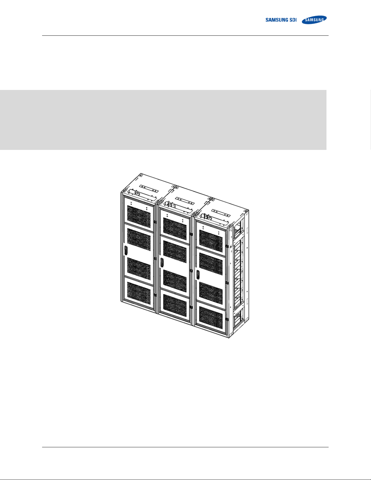
Lithium Ion Battery System for UPS
Installation Manual
(136S)
ET003222373 English 4/2018. Rev 0.0

Read this manual carefully before starting to install the battery system.
Keep these instructions for future reference.
ET003222373 English 4/2018. Rev 0.0

Copyright © 2017 SAMSUNG SDI Co., Ltd. All rights reserved.
This document contains information that is the property of SAMSUNG SDI Co., Ltd., and provides
for the sole purpose of the installation, operation, and maintenance of products of SAMSUNG SDI
Co., Ltd. No part of this publication is to be used for any other purpose, and it is not to be
reproduced, copied, disclosed, transmitted, stored in a retrieval system, or translated into any
human or computer language, in any form, by any means, in whole or in part, without prior written
consent of SAMSUNG SDI Co., Ltd.
Although every possible effort has been made to ensure the accuracy of this document, SAMSUNG
SDI Co., Ltd. assumes no responsibility for errors that may appear herein. The information is
subject to change without notice.
ET003222373 English 4/2018. Rev 0.0

ET003222373 English 4/2018. Rev 0.0
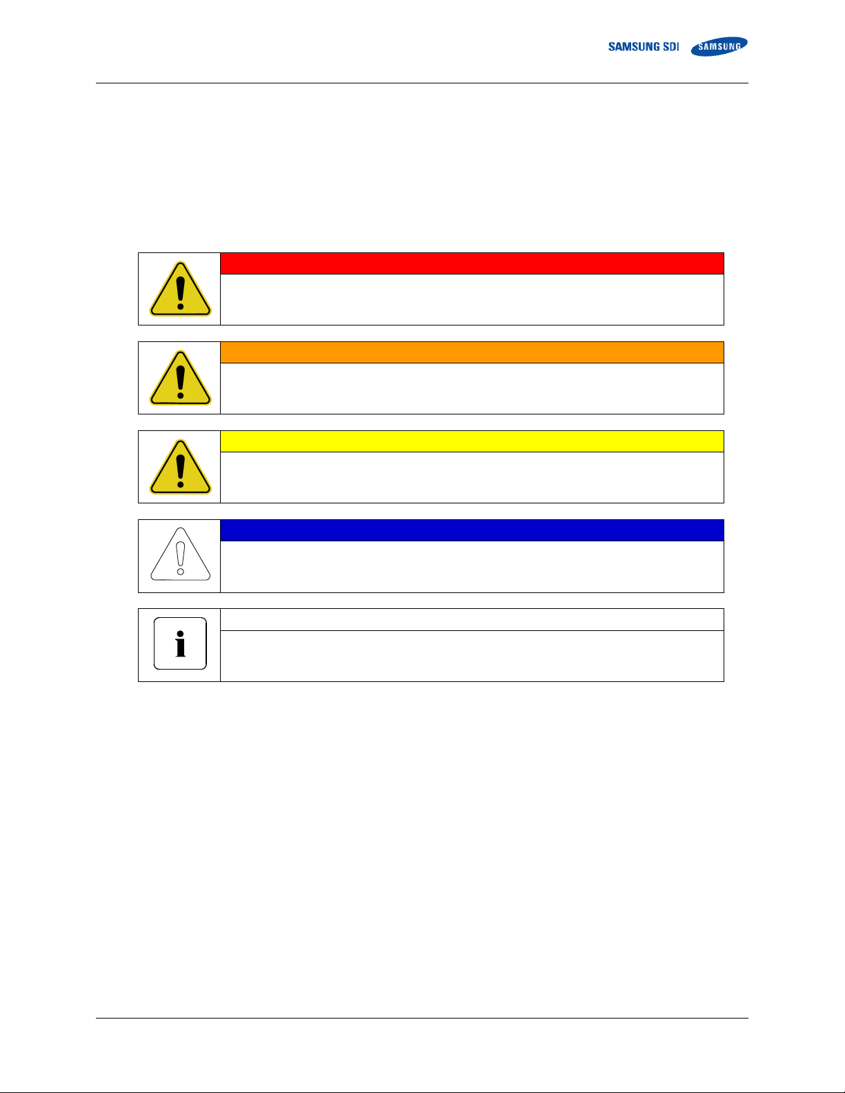
Important Safety Instructions
DANGER
Failure to comply with the instructions with this symbol may result in a serious accident,
causing death or a severe injury.
WARNING
Failure to comply with the instructions with this symbol may result in a serious accident,
causing a severe injury.
CAUTION
Failure to comply with the instructions with this symbol may result in minor or moderate
injury.
NOTICE
Provides information considered important but not hazard-related. The information relates
to property damage.
Important
Indicates valuable tips for optimal installation and operation of the product.
Important Safety Instructions
Read and follow these instructions!
The following precautions are intended to ensure your safety and prevent property damage. Before
installing this product, be sure to read all safety instructions in this document for proper installation.
ET003222373 English 4/2018. Rev 0.0 i

Important Safety Instructions
General Instructions
Please be aware that a battery presents a risk of electrical shock including high short-circuit current.
Follow all safety precautions while operating the batteries.
Remove watches, rings, and other metallic accessories.
Use tools with insulated handles in order to avoid inadvertent short circuits.
Wear rubber gloves and safety boots.
Do not put tools or any metal parts on the top of the batteries.
Disconnect charging source and load before connecting or disconnecting terminals.
Use proper lifting means when moving batteries and wear all appropriate safety clothing and
equipment.
Batteries must be handled, transported and recycled or discarded in accordance with federal, state,
and local regulations. Do not dispose of the batteries in a fire because they can explode.
Do not open or mutilate the batteries.
Only authorized, trained technicians should perform annual preventive maintenance.
Only qualified personnel who are familiar with the batteries and safety precautions should perform
installation or maintenance of the battery.
Do not allow unauthorized personnel to contact the batteries.
Safety Precautions
The following precautions provide general safety guidelines that should be followed when working
with or near the Energy Storage System (ESS). Complete safety parameters and procedures are
site-specific and should be developed by the customer for the installation site.
Review and refer to all safety warnings and cautions in this manual before installation.
Build a clear, permanent, restricted access area around the system.
Only authorized, adequately trained electrical operators should be able to access the system.
The interior design of this equipment must be considered a ―no-go area except for non-qualified
personnel who are familiar with the batteries and safety precautions,‖ depending on the location.
Consult local codes and applicable rules and regulations to determine permit requirements. If
required, mark enclosures appropriately before beginning work.
ii ET003222373 English 4/2018. Rev 0.0
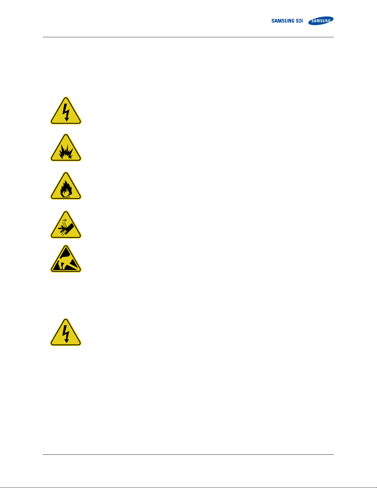
Important Safety Instructions
WARNING—SHOCK HAZARD
Do not contact system connectors or terminals. Do not open the enclosure doors unless proper
lock out/tag out procedures and related trainings are followed in accordance with the local codes
and regulations.
WARNING—ARC FLASH HAZARD
There is an arc flash hazard associated with all electrical equipment. There is a serious risk of
arc flash relating to any equipment modification (e.g. opening doors). Serious injuries can occur
in arc flash incidents. Appropriate training is required in accordance with local codes and
regulations.
WARNING—FIRE HAZARD
Fire may occur under certain fault conditions.
CAUTION—PINCH POINTS
Multiple pinch-points are present in most system components. Be aware that there is a serious
risk of injury while working around and in equipment enclosures.
CAUTION—STATIC SENSITIVE
Electronic appliances can be damaged by electrostatic discharge. Proper handling procedures
are required. Be sure to wear a grounded anti-static wrist strap and to discharge static electricity
by touching a grounded surface near the equipment before touching any system components.
DANGER
The ESS is powered by multiple power sources. Hazardous voltages may be present in the
equipment even when it does not appear operational. Make sure that you completely
understand the cautions and warnings in this installation manual. Failure to do so may result in
serious injury or death. Follow all manufacturer-published safety procedures.
Electrical equipment can present a risk of electrical shock and can cause arc flash. The
following precautions must be observed when working on or around electrical equipment:
Personnel and Equipment Warnings
Personnel in contact with the battery system should be aware of the following hazards:
Dangerous Voltages
Remove watches, jewelry, rings, and other metallic objects.
Use tools with insulated handles.
Safety clothing and shoes must comply with local codes and regulations.
ET003222373 English 4/2018. Rev 0.0 iii
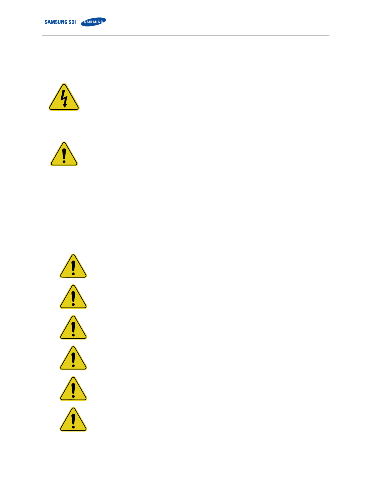
Important Safety Instructions
DANGER
Follow all applicable lock out/tag out procedures at all times. Failure to follow proper lock out/tag
out procedures may result in serious injury or death.
With power applied to the ESS, hazardous voltages are present on some components. To
prevent accidental death or injury, do not touch any components within the enclosure unless you
are specifically directed to do so. To reduce the risk of electrical shock, make sure that all
equipment is properly grounded. For more information, refer to 3.1 Grounding the Battery
System.
WARNING
Enclosure doors must remain closed except when access to the enclosure interior is required. If
possible, personnel should keep a safe distance from enclosures whenever the equipment is
energized. Always comply with local, state, and national lock out/tag out guidelines when working
with or near the ESS. The lock out/tag out procedures must meet or exceed the requirements of
all guidelines presented in SAMSUNG SDI safety documentation. Before entering potentially
hazardous areas or beginning work on the ESS, complete the following tasks:
DANGER
When energized, this equipment presents a potential hazard of electric shock, death, and
burn. Only authorized personnel who are thoroughly familiar with the equipment and
adequately trained should install, operate, or maintain this equipment.
DANGER
To avoid death, personal injury, or damage to the product, follow all safety procedures as
regulated by Environmental Health and Safety (EHS) guidelines.
DANGER
To minimize the hazards of electrical shock, death, and burns, approved grounding
practices and procedures should be strictly followed.
WARNING
To avoid personal injury and damage to equipment, personnel must adhere to the site
protocol concerning working at heights.
WARNING
To avoid personal injury or equipment damage caused by equipment malfunction, only
adequately trained personnel should modify any programmable machine.
WARNING
Always ensure that applicable standards and regulations are followed and only properly
certified equipment is used as a critical component of a safety system. Never assume that
a safety-critical control loop is functioning correctly.
Lock Out/Tag Out Guidelines
Identify and wear protective clothing and shoes.
Identify and isolate all power and stored energy sources.
Apply appropriate lock out/tag out devices. When applying lock out/tag out to the ESS, do not touch
anything within the enclosure except as specifically directed in the work procedures.
Complete the site-specific lock out/tag out procedures and safety checklist before beginning work.
General Warnings
iv ET003222373 English 4/2018. Rev 0.0

Table of Contents
Table of Contents
Important Safety Instructions ..................................................................................................... i
General Instructions.............................................................................................................................. ii
Safety Precautions ............................................................................................................................... ii
Personnel and Equipment Warnings .................................................................................................... iii
Dangerous Voltages ............................................................................................................................. iii
Lock Out/Tag Out Guidelines ............................................................................................................... iv
General Warnings ................................................................................................................................ iv
Table of Contents ......................................................................................................................... i
Tables .......................................................................................................................................... iii
Figures ........................................................................................................................................ iv
1. About this Manual ................................................................................................................... 1
1.1 Purpose ....................................................................................................................................... 1
1.2 Target Audience ........................................................................................................................... 1
1.3 Organization ................................................................................................................................ 1
1.4 Revision History ........................................................................................................................... 2
1.5 Acronyms and Abbreviations ....................................................................................................... 2
2. Product Description ............................................................................................................... 3
2.1 Major Components ...................................................................................................................... 3
2.1.1 Battery Module (Type A / Type B) ................................................................................... 4
2.1.2 Switchgear Assembly ..................................................................................................... 5
2.1.3 SMPS Assembly (Type A / Type B) ................................................................................. 6
2.1.4 Rack Frame .................................................................................................................... 7
3. Assembling the Product ........................................................................................................ 8
3.1 Grounding the Battery System ..................................................................................................... 8
3.2 Installation and Assembly Procedure ........................................................................................... 9
3.3 Preparation Stage—Procedure .................................................................................................. 10
3.4 Preparation Stage - Unpacking .................................................................................................. 11
3.5 Preparation Stage - Ground Wire and Tools .............................................................................. 11
3.5.1 Ground Wires ............................................................................................................... 11
3.5.2 Ground Wire Fasteners ................................................................................................ 11
3.5.3 Rack Fasteners (Anchors) ............................................................................................ 11
3.5.4 Multiple Rack Fasteners ............................................................................................... 11
3.6 Preparation Stage—Recommended Tools/Instruments ............................................................. 12
3.7 Preparation Stage - Visual Inspection ........................................................................................ 14
3.7.1 Inspecting the Rack Frame ........................................................................................... 14
3.7.2 Visual Inspection of the Modules .................................................................................. 15
3.7.3 Inspecting the Switchgear ............................................................................................ 15
3.7.4 Inspecting the SMPS assembly .................................................................................... 15
3.8 Rack Anchoring Stage ............................................................................................................... 16
3.9 Rack Installation Stage .............................................................................................................. 21
3.9.1 Switchgear and SMPS Assembly Installation ............................................................... 22
3.9.2 Battery Module Installation ........................................................................................... 26
3.9.3 Busbar Installation ........................................................................................................ 29
3.9.4 Module and Switchgear Signal Cable Connection ........................................................ 63
3.9.5 SMPS Assembly and Switchgear Power Cable Connection ......................................... 75
3.9.6 SMPS Assembly and Switchgear Signal Cable Connection ......................................... 76
ET003222373 English 4/2018. Rev 0.0 i

Table of Contents
3.9.7 SMPS Assembly AC Input Connection ......................................................................... 78
3.9.8 Rack Fuse and Additional Module Signal Cable Connection ........................................ 80
3.9.9 DC Link Cable Connection ........................................................................................... 85
3.9.10 AC Input Commissioning .............................................................................................. 87
4. Performance .......................................................................................................................... 88
4.1 Operating Conditions ................................................................................................................. 88
4.2 Control Power Requirements ..................................................................................................... 88
4.3 Hardware ................................................................................................................................... 88
ii ET003194024 English 5/2017. Rev 0.0

Table of Contents
Tables
Table 3-1: Ground Wire Specifications ......................................................................................................... 11
Table 3-2: Ground Wire Fastener Specification ............................................................................................ 11
Table 3-3: Rack Fastener Specifications ...................................................................................................... 11
Table 3-4: Rack Fastener Specifications (Side by side) ............................................................................... 11
Table 3-5: Recommended Tools and Instruments ........................................................................................ 12
Table 3-6: Module Voltage and Internal Impedance ..................................................................................... 15
Table 3-7: Rack Clearance Distances .......................................................................................................... 16
Table 4-1: Control Power Range of Operation .............................................................................................. 88
Table 4-2: Hardware Description .................................................................................................................. 88
ET003222373 English 4/2018. Rev 0.0 iii

Table of Contents
Figures
Figure 2-1: Battery Modules (Type A and Type B).......................................................................................... 4
Figure 2-2: Switchgear Assembly ................................................................................................................... 5
Figure 2-3: Front View of the Switchgear Assembly ....................................................................................... 5
Figure 2-4: SMPS Assembly (Type A and Type B) ......................................................................................... 6
Figure 2-5: Rack Frame .................................................................................................................................. 7
Figure 3-1: Installation Procedure ................................................................................................................... 9
Figure 3-2: Faulty Cases .............................................................................................................................. 14
Figure 3-3: Clearance Distance for Single Rack Frame ................................................................................ 17
Figure 3-4: Clearance Distance for Multiple Rack Frames ........................................................................... 17
Figure 3-5: Clearance Distance for Multiple Rack Frames Installed Rear-to-Rear ....................................... 18
Figure 3-6: Rack Anchoring Points (4 EA) .................................................................................................... 19
Figure 3-7: Holes on the sides of the rack .................................................................................................... 19
Figure 3-8: Reattaching the Side Panels ...................................................................................................... 19
Figure 3-9: Reattaching the Rear Panels ...................................................................................................... 20
Figure 3-10: Inserting Switchgear ................................................................................................................. 22
Figure 3-11: Attaching a Switchgear Assembly to a Rack Frame ................................................................. 22
Figure 3-12: Ground Cable Connection to the Switchgear Assembly ........................................................... 23
Figure 3-13: Inserting SMPS Assembly ........................................................................................................ 24
Figure 3-14: Attaching the SMPS Assembly ................................................................................................. 24
Figure 3-15: Ground Cable Connection to the SMPS Assembly .................................................................. 25
Figure 3-16: Insertion of Modules on the Ninth Shelf from the Bottom ......................................................... 26
Figure 3-17: Battery Module Arrangement on Eighth and Ninth Shelves...................................................... 27
Figure 3-18: Battery Module Arrangement .................................................................................................... 27
Figure 3-19 : Module Number ....................................................................................................................... 28
Figure 3-20: Insertion of modules on 1st shelf .............................................................................................. 28
Figure 3-21: Removing the Module #1’s Cover and Switchgear B- Terminal Cover ..................................... 30
Figure 3-22: Connect Switchgear B- and Module #1 B- ................................................................................ 30
Figure 3-23: Restore Switchgear’s B- Terminal ............................................................................................ 31
Figure 3-24: Remove Battery Module #2’s Front Cover ................................................................................ 31
Figure 3-25: Connect Battery Module #1 B+ and Battery Module #2 B-. ...................................................... 32
Figure 3-26: Reattach Battery Module #1’s Front Cover ............................................................................... 33
Figure 3-27: Remove Battery Module #2’s Front Cover ................................................................................ 33
Figure 3-28: Connect Battery Module #2 B+ and Battery Module #3 B-. ...................................................... 34
Figure 3-29: Reattach Battery Module #2’s Front Cover ............................................................................... 35
Figure 3-30: Remove Battery Module #4’s Front Cover ................................................................................ 35
Figure 3-31: Connect Battery Module #3 B+ and Module #4 B-. .................................................................. 36
Figure 3-32: Reattach Battery Module #3’s Front Cover ............................................................................... 37
Figure 3-33: Remove Battery Module #5’s Front Cover ................................................................................ 37
Figure 3-34: Connect Battery Module #4 B+ and Battery Module #5 B-. ...................................................... 38
Figure 3-35: Reattach Battery Module #4’s Front Cover ............................................................................... 39
Figure 3-36: Remove Battery Module #6’s Front Cover ................................................................................ 39
Figure 3-37: Connect Battery Module #5 B+ and Battery Module #6 B-. ...................................................... 40
Figure 3-38: Reattach Battery Module #5’s Front Cover ............................................................................... 41
Figure 3-39: Remove Battery Module #7’s Front Cover ................................................................................ 41
Figure 3-40: Connect Battery Module #6 B+ and Battery Module #7 B- ....................................................... 42
Figure 3-41: Reattach Battery Module #6’s Front Cover ............................................................................... 43
Figure 3-42: Remove Battery Module #8’s Front Cover ................................................................................ 43
Figure 3-43: Connect Battery Module #7 B+ and Battery Module #8 B- ....................................................... 44
Figure 3-44: Reattach Battery Modules #7 and #8’s Front Covers ............................................................... 45
Figure 3-45: Remove Front Covers from Battery Modules #9 and #10 ......................................................... 45
Figure 3-46: Connect Battery Module #9 B+ and Battery Module #10 B-. .................................................... 46
Figure 3-47: Reattach Battery Module #9’s Front Cover ............................................................................... 47
Figure 3-48: Remove Battery Module #11’s Front Cover .............................................................................. 47
Figure 3-49: Connect Battery Module #10 B+ and Battery Module #11 B-. .................................................. 48
Figure 3-50: Reattach Battery Module #10’s Front Cover ............................................................................. 49
Figure 3-51: Remove Battery Module #12’s Front Cover .............................................................................. 49
Figure 3-52: Connect Battery Module #11 B+ and Battery Module #12 B-. .................................................. 50
Figure 3-53: Assemble Module #11’s Front Cover........................................................................................ 51
iv ET003194024 English 5/2017. Rev 0.0

Table of Contents
Figure 3-54: Remove Module #13’s Front Cover .......................................................................................... 51
Figure 3-55: Connect Battery Module #12B+ and Battery Module #13 B-. ................................................... 52
Figure 3-56: Assemble Module #12’s Front Cover........................................................................................ 53
Figure 3-57: Remove Battery Module #14’s Front Cover .............................................................................. 53
Figure 3-58: Connect Battery Module #13 B+ and Battery Module #14 B-. .................................................. 54
Figure 3-59: Reattach Battery Module #13’s Front Cover ............................................................................. 55
Figure 3-60: Remove Battery Module #15’s Front Cover .............................................................................. 55
Figure 3-61: Connect Battery Module #14 B+ and Battery Module #15 B-. .................................................. 56
Figure 3-62: Assemble Battery Module #14’s Front Cover ........................................................................... 57
Figure 3-63: Remove Battery Module #16’s Front Cover .............................................................................. 57
Figure 3-64: Connect Battery Module #15 B+ and Battery Module #16 B-. .................................................. 58
Figure 3-65: Reattach Battery Module #15’s Front Cover ............................................................................. 59
Figure 3-66: Remove Battery Module #17’s Front Cover .............................................................................. 59
Figure 3-67: Connect Battery Module #15 B+ and Battery Module #16 B-. .................................................. 60
Figure 3-68: Reattach Battery Module #15’s Front Cover ............................................................................. 61
Figure 3-69: Remove Switchgear B+ Terminal Cover .................................................................................. 61
Figure 3-70: Connect Switchgear B+ and Module #17 B+. ........................................................................... 62
Figure 3-71: Reattach Battery Module #16’s Front Cover and Switchgear B+ Terminal Cover .................... 62
Figure 3-72: Rack BMS to Module #1 OUT Signal Cable ............................................................................. 63
Figure 3-73: Opening for Cable Installation .................................................................................................. 64
Figure 3-74: Module #1 to Module #2 Signal Cabling ................................................................................... 64
Figure 3-75: Module #2 to Module #3 Signal Cabling ................................................................................... 65
Figure 3-76: Module #3 to Module #4 Signal Cabling ................................................................................... 65
Figure 3-77: Module #4 to Module #5 Signal Cabling ................................................................................... 66
Figure 3-78: Module #5 to Module #6 Signal Cabling ................................................................................... 66
Figure 3-79: Module #6 to Module #7 Signal Cabling ................................................................................... 67
Figure 3-80: Module #10 to Module #11 Signal Cabling ............................................................................... 67
Figure 3-81: Module #11 to Module #12 Signal Cabling ............................................................................... 68
Figure 3-82: Module #12 to Module #13 Signal Cabling ............................................................................... 68
Figure 3-83: Module #13 to Module #14 Signal Cabling ............................................................................... 69
Figure 3-84: Module #14 to Module #15 Signal Cabling ............................................................................... 69
Figure 3-85: Module #15 to Module #16 Signal Cabling ............................................................................... 70
Figure 3-86: Module #16 to Module #17 Signal Cabling ............................................................................... 70
Figure 3-82: Module #15 to Module #16 Signal Cabling ............................................................................... 71
Figure 3-83: Pre-Punched Hole for Signal Cable .......................................................................................... 72
Figure 3-84: Signal Cabling Examples of Left Alignment of Switchgear ....................................................... 73
Figure 3-85: Openings for Cable................................................................................................................... 73
Figure 3-86: Termination Resistor Setting for Last Switchgear ..................................................................... 73
Figure 3-87: DC Power Cables from SMPS Assembly Type A to Switchgear .............................................. 75
Figure 3-88: DC Power Cables from SMPS Assembly Type B to Switchgear .............................................. 75
Figure 3-89: CAN Signal Cable Connection from SMPS Assembly to Switchgear ....................................... 76
Figure 3-90: TCP/IP Cable Connection to SMPS Assembly ......................................................................... 76
Figure 3-91: Dry Contact Cable Connection to SMPS Assembly ................................................................. 77
Figure 3-92: MCCB Extra Auxiliary Connection ............................................................................................ 77
Figure 3-93: AC Input Terminals ................................................................................................................... 78
Figure 3-94: AC Input Terminals with Cables Attached ................................................................................ 78
Figure 3-95: AC Input Terminals Protective Covers...................................................................................... 79
Figure 3-100: Remove Front Covers from Battery Modules #8 and #9 ......................................................... 80
Figure 3-101: Rack Fuse Busbar Assembly. ................................................................................................ 81
Figure 3-102: Rack Fuse Cover .................................................................................................................... 82
Figure 3-103: Rack Fuse Cover (Fully Assembled; Front View) ................................................................... 82
Figure 3-104: Reattach Front Covers to Battery Modules #8 and #9 ............................................................ 83
Figure 3-105: Battery Module #7 to Battery Module #8 Signal Cabling ........................................................ 83
Figure 3-106: Battery Module #8 to Battery Module #9 Signal Cabling (WIRE ASSY MODULE TO MODULE
#2) ......................................................................................................................................................... 84
Figure 3-107: Battery Module #9 to Battery Module #10 Signal Cabling ...................................................... 84
Figure 3-105: Grounding Points (2 EA) ......................................................................................................... 85
Figure 3-106: Connecting the DC Link High Current Cables ........................................................................ 86
ET003222373 English 4/2018. Rev 0.0 v


1. About this Manual
1. About this Manual
To make sure that you understand the proper procedures for safe operation, this section briefly
describes the purpose, audience, organization, revision history, and acronyms and abbreviations.
1.1 Purpose
The purpose of this manual is to provide information for the safe and successful assembly of the
product.
This product requires configuration by a factory trained service.
The instructions in this manual are based on assembly of a three-cabinet system. Other
configurations are possible and these instructions can be reduced or expanded to accommodate
installation of those systems.
1.2 Target Audience
This installation manual is intended for trades suitable for assembling electrical and electronic
assemblies.
1.3 Organization
This manual is composed of the following chapters:
Chapter 1 ―About this Manual‖ outlines this document.
Chapter 2 ―Product Description‖ describes the major components of the product.
Chapter 3 ―Assembling the Product‖ explains how to install the product.
ET003222373 English 4/2018. Rev 0.0 1

1. About this Manual
Rev.
Description
Author
Date
0.0
2018.04.08
Abbreviations
Full Name
AED
Automated External Defibrillator
BMS
Battery Management System
EHS
Environmental Health and Safety
ESS
Energy Storage System
LOTO
LOCK OUT/TAG OUT
OT
Overtemperature
OVP
Overvoltage Protection
PCS
Power Conversion System
SMPS
Switched Mode Power Supply
SOC
State Of Charge
SOH
State Of Health
SG
Switchgear
UT
Undertemperature
UVP
Undervoltage Protection
UPS
Uninterruptible Power Supply
1.4 Revision History
First Release (customer facing)
1.5 Acronyms and Abbreviations
The following acronyms and abbreviations are used in this manual.
2 ET003222373 English 4/2018. Rev 0.0

2. Product Description
2. Product Description
Before operating the battery system, users must be familiar with its components.
2.1 Major Components
Samsung SDI’s Lithium Ion Battery System has the following components:
Battery Module (Type A / Type B)
Switchgear Assembly
SMPS Assembly (Type A / Type B)
Rack Frame
ET003222373 English 4/2018. Rev 0.0 3
2. Product Description
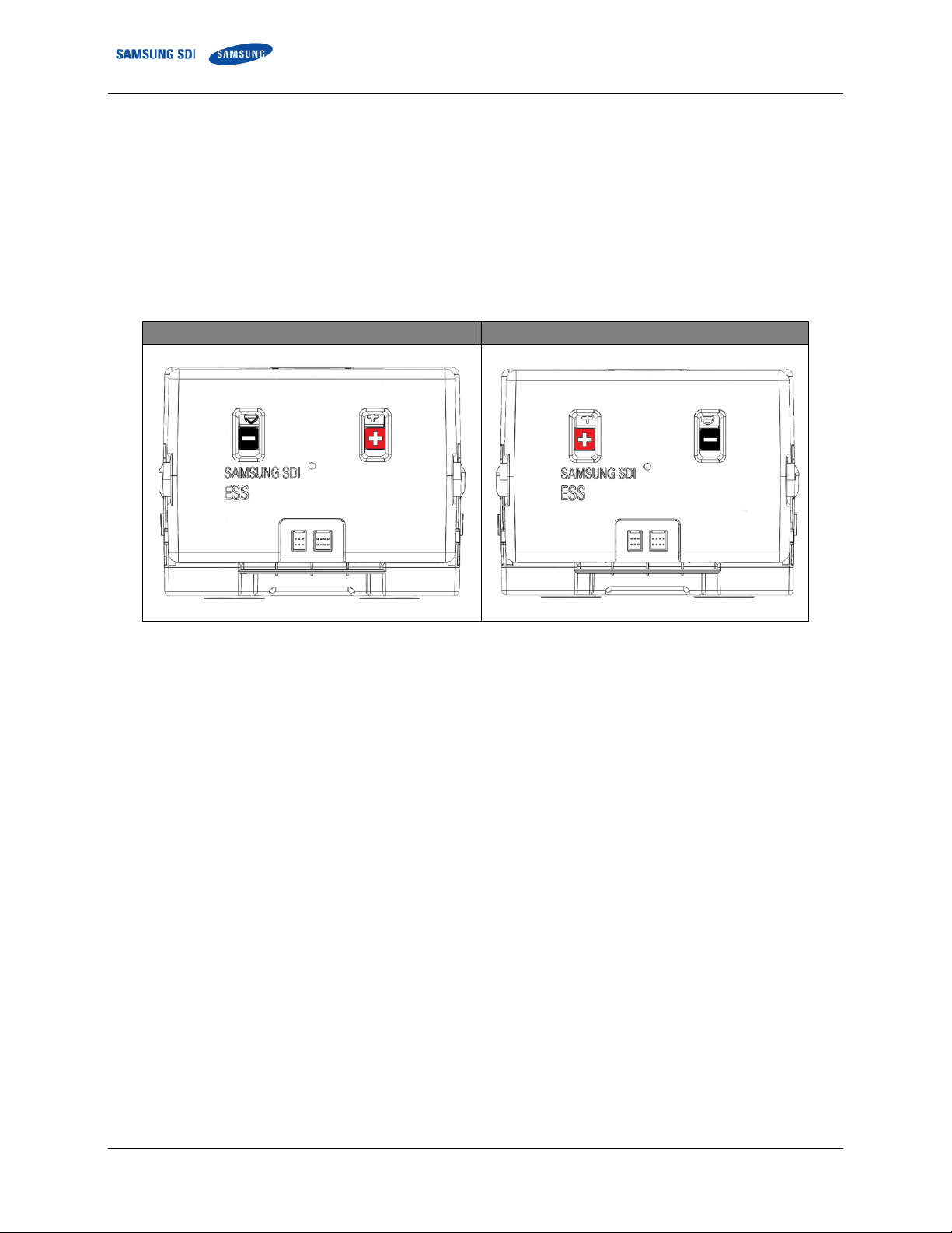
Battery Module Type A (Front)
Battery Module Type B (Front)
2.1.1 Battery Module (Type A / Type B)
The battery module consists of battery cells. Each battery module has a module BMS (Battery
Management System).
There are two types of Battery Modules. The model number for each type is determined by the position of
polarity. Type A’s positive (+) terminal is on the right side viewed from the front. The positive terminal for
Type B is on the left.
Following are front and rear views of module assemblies.
Figure 2-1: Battery Modules (Type A and Type B)
4 ET003222373 English 4/2018. Rev 0.0
2. Product Description
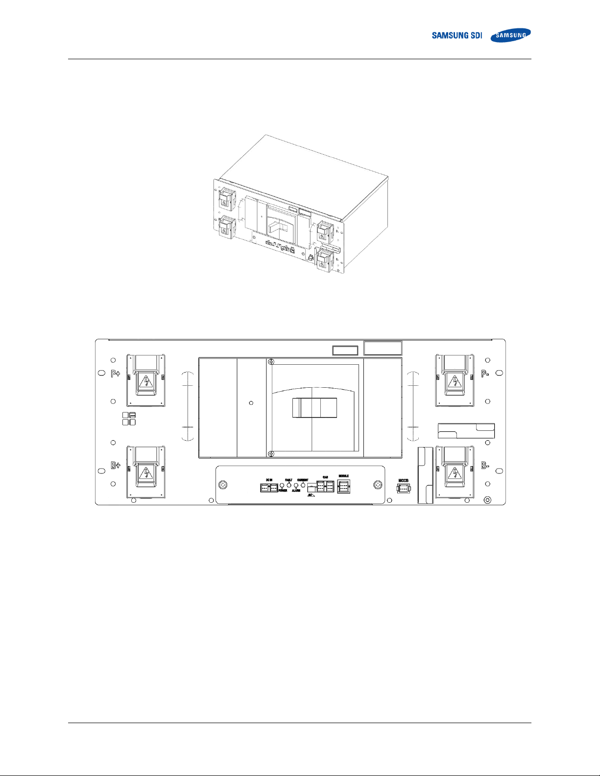
2.1.2 Switchgear Assembly
The Switchgear Assembly consists of a protective circuit and a rack BMS. It is connected to the UPS
using the positive and negative power terminals on the front of switchgear.
Figure 2-2: Switchgear Assembly
The switchgear provides an auxiliary breaker switch that can be connected to an external building
monitoring system.
Figure 2-3: Front View of the Switchgear Assembly
ET003222373 English 4/2018. Rev 0.0 5
2. Product Description
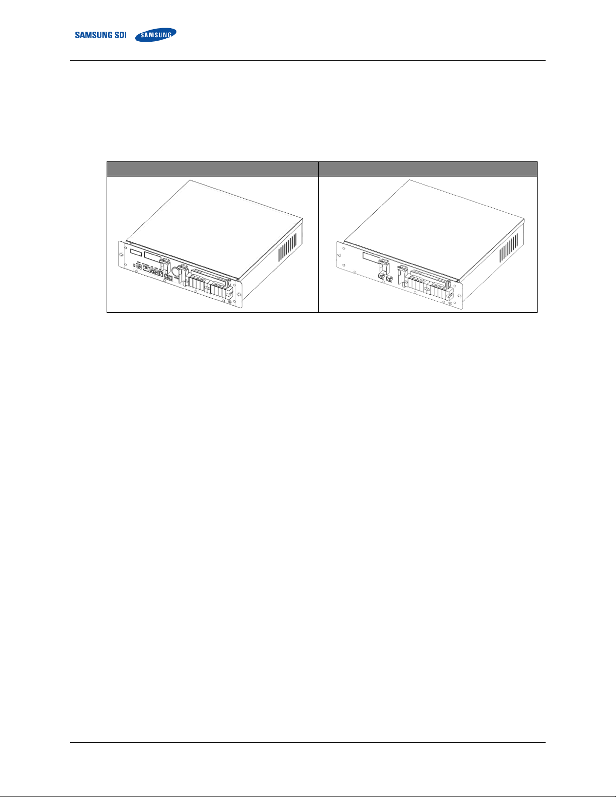
Front SMPS Assembly Type A
Front SMPS Assembly Type B
2.1.3 SMPS Assembly (Type A / Type B)
The SMPS Assembly provides data to the external systems (i.e., building management system, UPS, etc.)
while controlling and monitoring all connected Rack BMS’s.
There are two types of SMPS Assemblies: Type A has a System BMS; Type B does not.
Figure 2-4: SMPS Assembly (Type A and Type B)
The SMPS Assembly provides these communication protocols: RS485, TCP/IP and dry contact.
6 ET003222373 English 4/2018. Rev 0.0
2. Product Description
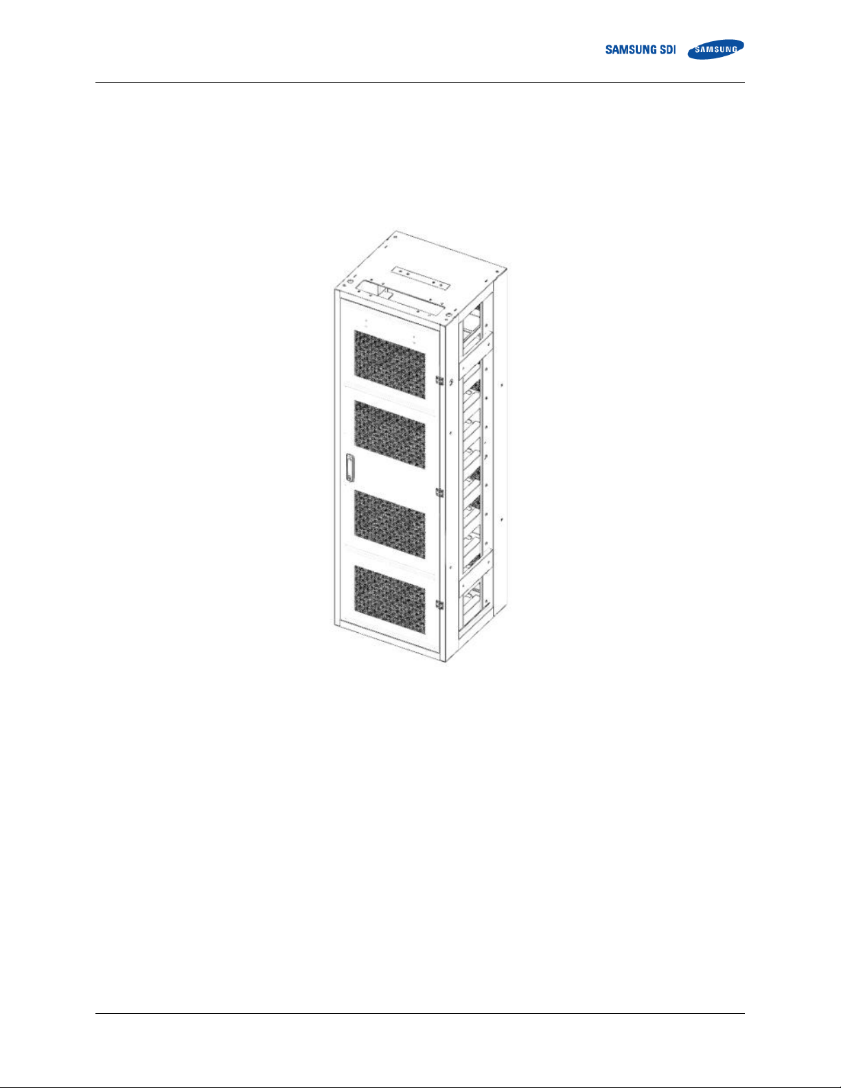
2.1.4 Rack Frame
The Rack Frame is used to mount the Battery Modules, Switchgear Assembly and SMPS Assembly. It
facilitates grounding of the installed components. Grounding cable/busbar for the rack frame is necessary
for the Switchgear and SMPS Assemblies because they are grounded to the rack frame when installed.
An equipment grounding conductor is required to ground the rack frames together and to the UPS module.
Figure 2-5: Rack Frame
ET003222373 English 4/2018. Rev 0.0 7
3. Assembling the Product
WARNING
The power terminal cap must be left in place on the power terminal of the tray for
insulation.
Be sure to use insulated tools (torque wrench, extension, socket, etc.).
All the instruments must be insulated and no metal articles (e.g. watch, ring) should be
present in the installation area.
All power switches must be turned off in advance.
Prepare a CO2 fire extinguisher, a first aid kit, and an AED (automated external
defibrillator) before installation.
CAUTION
If available, use a mechanical lift for lifting heavy (22 kg [50 lb.]) components. If there is
no lift, two or three workers must move items weighing more than 22 kg (50 lb.).
The ambient temperature range must be 23°C ±5°C during installation.
WARNING—SHOCK HAZARD
Verify with a voltmeter that no power is present on the system before beginning work on the
battery system or other part of the UPS system. Use lock out/tag out procedures to secure the
UPS and batteries Do not contact system connectors or terminals. Follow all applicable safety
measures.
Follow all local and national codes and regulations.
3. Assembling the Product
Because this product has a battery with more than 300V present when fully assembled, you must
follow the general safety Instructions. This system must be installed by qualified, trained workers
familiar with the required instruments. Use appropriate lifting methods when moving the batteries.
3.1 Grounding the Battery System
Grounding methods and wiring must comply with NEC Article 250.
Grounding is required to prevent electric shock hazards and reduce or eliminate damage caused by
electrical noise. Ground connections and ground wire routing vary significantly depending on
system configuration and equipment layout. Samsung provides two grounding strips on each rack,
one on top of the rack and the other on the bottom of the rack. See Figure 3-109: Grounding Points
(2 EA).
8 ET003222373 English 4/2018. Rev 0.0

3. Assembling the Product
1. Preparation
Stage
2. Rack Anchoring
Stage
3. Rack
Installation
Stage
4. System
Installation Stage
3.2 Installation and Assembly Procedure
This product must be installed and assembled by following the procedure below:
Figure 3-1: Installation Procedure
Preparation Stage
Procedure
Unpacking
Ground wire and tools
Recommended tools and instruments
Appearance inspection
Rack Anchoring Stage
Transport the rack frame to the installation location after unpacking
Arrange the rack frame after checking the positions of holes in the frame and anchoring points
Perform the anchoring and ground connections
Rack Installation Stage
Transport the battery modules to the installation location
Place the battery modules in the rack frame
Insert the Switchgear assembly in the rack frame
Insert the SMPS assembly in the rack frame
After all subassemblies are inserted in the rack frame, attach the subassemblies to the rack frame
Connect the busbars
Connect the signal cables from switchgear to module, and module to module
Connect the signal cables from switchgear to switchgear
System Installation Stage
Connect the SMPS assembly
Perform installation checks
Prepare the items for BMS configuration
Configure the BMS EEPROM settings
ET003222373 English 4/2018. Rev 0.0 9
3. Assembling the Product
WARNING
Do not wear watches, rings, jewelry, or any other metal objects.
Wear electrically insulated gloves and safety shoes.
CAUTION
Store the product in a dust-free place with the moisture level of below 60% and the
temperature level of 23°C ±5°C.
Keep components out of direct sunlight.
3.3 Preparation Stage—Procedure
For the preparation stage, perform the following steps:
1. Create the installation plan and check the equipment and instruments for installation.
2. Check the arrival schedule of the parts required.
3. Unpack the equipment.
4. Inspect the equipment.
10 ET003222373 English 4/2018. Rev 0.0

3. Assembling the Product
Wire No.
Terminal Type
#1AWG or thicker
M12 2 Hole Ring Terminal
Size
Hardness
Thread Pitch
Material
M12–30mm
70 (Grade 7)
1.25 mm (0.05 in)
SS304
Size
Hardness
Thread Pitch
Material
M16–L
(Bottom Anchor)
70 (Grade 7)
2.0 mm (0.08 in)
SS304
Size
Hardness
Thread Pitch
Material
M10–25mm (Side)
70 (Grade 7)
1.5 mm (0.06 in)
SS304
1
2
3
3.4 Preparation Stage - Unpacking
Check the parts during unpacking:
3.5 Preparation Stage - Ground Wire and Tools
Ground wires for the racks must be provided by the installer. Installer-supplied ground wires must
meet the specifications below.
3.5.1 Ground Wires
Use ground wire that is #1AWG. The ground wire specifications are:
Table 3-1: Ground Wire Specifications1
3.5.2 Ground Wire Fasteners
Specifications for the ground wire fastening screws are:
Table 3-2: Ground Wire Fastener Specification2
3.5.3 Rack Fasteners (Anchors)
Specifications for the rack fastener screws for anchoring the rack frame to the floor are:
Table 3-3: Rack Fastener Specifications3
3.5.4 Multiple Rack Fasteners
Specifications for the rack fastener screws for installing multiple rack frames side-by-side are:
Table 3-4: Rack Fastener Specifications (Side by side)
Not provided. Must be provided by the installer or customer.
Not provided. Must be provided by the installer or customer.
Not provided. Must be provided by the installer or customer.
ET003222373 English 4/2018. Rev 0.0 11
3. Assembling the Product
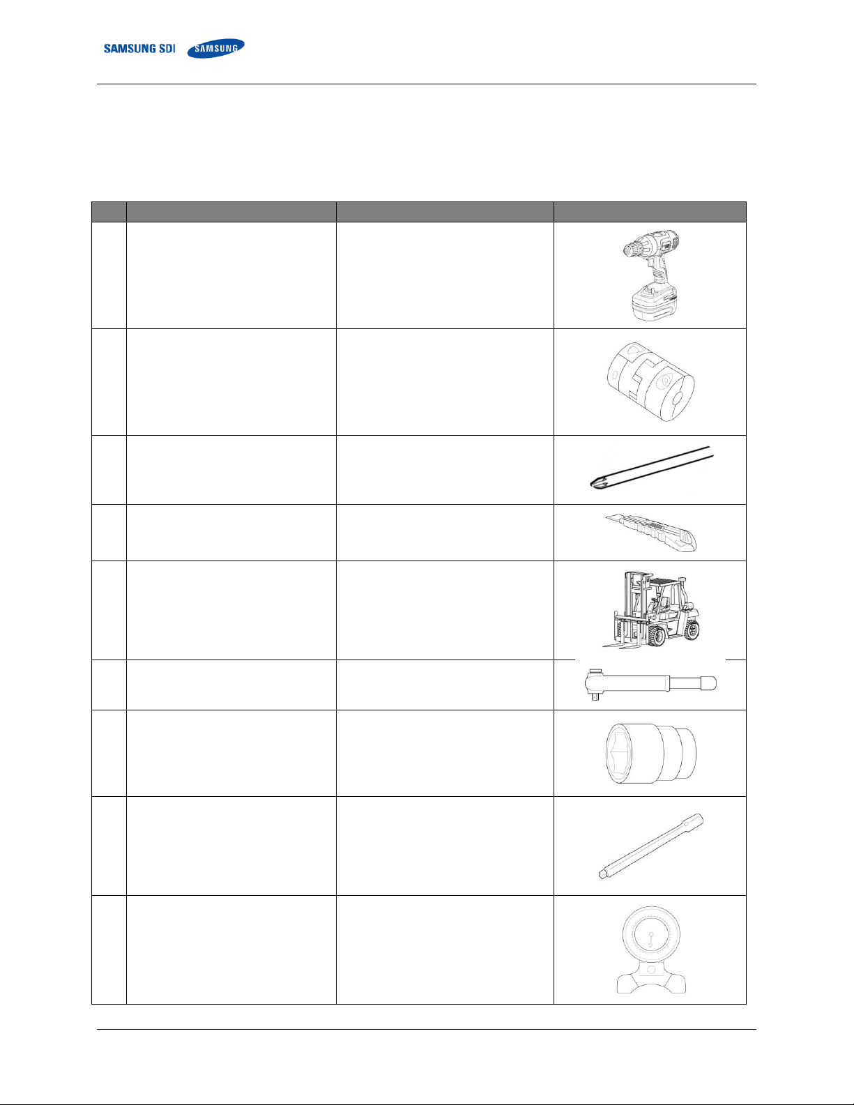
No.
Items
Usage
Appearance
1
Power Screwdriver/Drill
(Max torque: 26Nm/270 kgf/cm)
To fasten switchgear and SMPS
assemblies to the rack frames
(5.1–6.1Nm/50–60 kgf/cm)
2
Torque Limiter
For use with torque wrench
3
Phillips Screwdriver or Bit
To fasten switchgear and SMPS
assemblies to the rack frames
(M5 Tip)
4
Box Cutter
Opening boxes
5
Forklift
Moving rack frames and pallets
containing modules and switchgear
6
Insulated Torque Wrench
Installing a high-current cable
8.16–30 Nm (72–265 in lbs)
7
Insulated Sockets
(13 mm, 17mm and 19mm)
Installing power cables and busbars
8
Insulated Extension for Socket
Installing a power cable
9
Inclinometer/Level
Installing a rack frame
3.6 Preparation Stage—Recommended Tools/Instruments
Installers must provide these tools for installing the battery:
Table 3-5: Recommended Tools and Instruments
12 ET003222373 English 4/2018. Rev 0.0

3. Assembling the Product
No.
Items
Usage
Appearance
10
Battery Tester
Measure battery module’s voltage
and internal impedance
ET003222373 English 4/2018. Rev 0.0 13
3. Assembling the Product
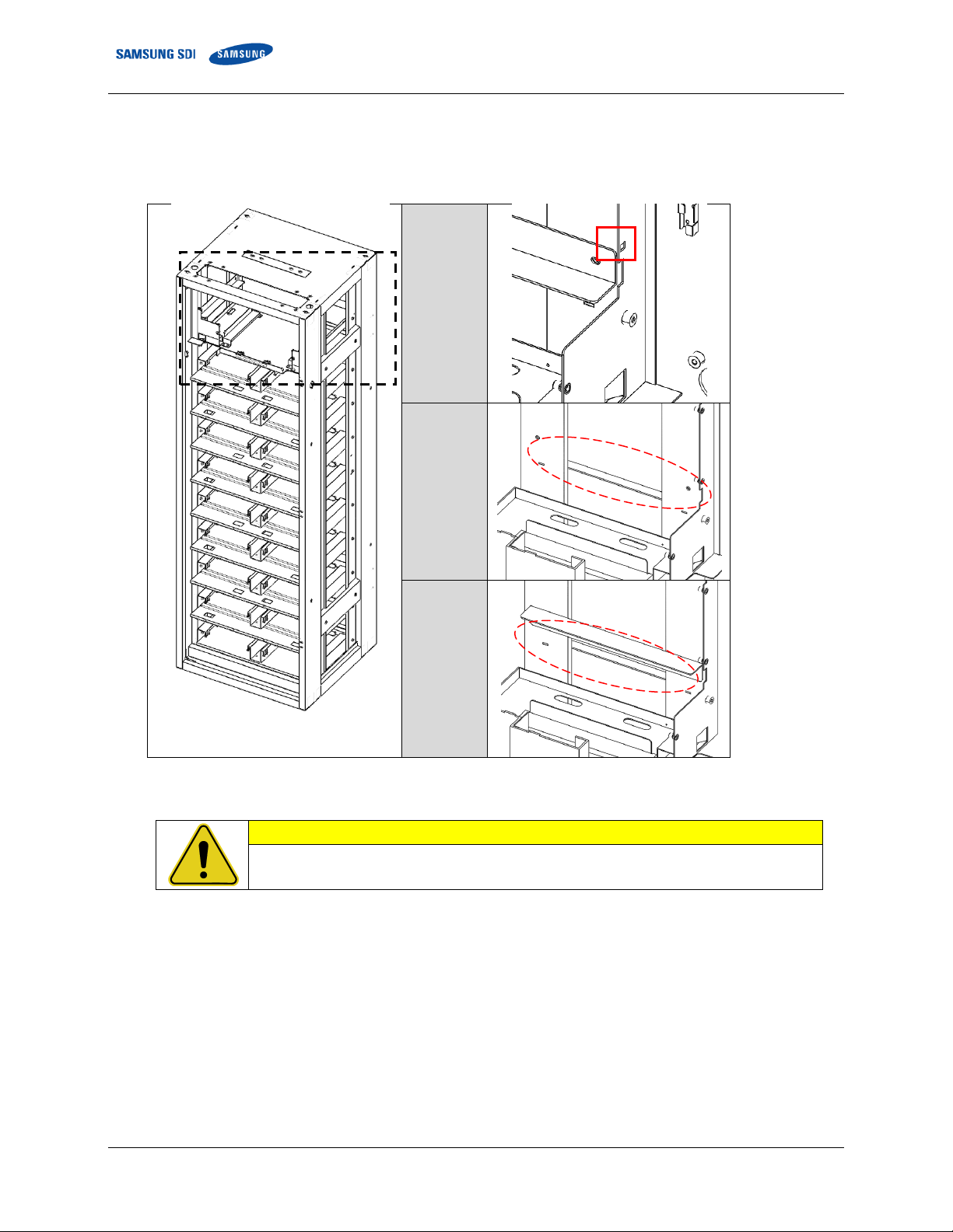
CAUTION
If any defects are found during the inspection, contact the SAMSUNG SDI customer
service department.
Missing
Cage
Nut
Missing
Guide
Rail
Guide Rail
Incorrect
Orientation
3.7 Preparation Stage - Visual Inspection
During visual inspection, the inspector should check for:
Figure 3-2: Faulty Cases
3.7.1 Inspecting the Rack Frame
After transporting the rack frame to the installation location, check for:
Structural damage
Paint peeling
Damaged or protruding screws.
After completion, install or package the rack for protection during storage.
14 ET003222373 English 4/2018. Rev 0.0

3. Assembling the Product
No.
Items
Value
1
Voltage Check
28.712 ~ 29.104V
2
Internal Impedance Check
3.0 ~ 4.3 mΩ
3.7.2 Visual Inspection of the Modules
After transporting the modules to the installation location, check for:
Physical damage to the exterior
Damaged or protruding screws
Proper voltage and internal impedance of the battery modules using the battery tester.
Table 3-6: Module Voltage and Internal Impedance
After completion, install the battery module in the previously installed rack or return the battery
module to its original packing for protection during storage.
3.7.3 Inspecting the Switchgear
After transporting the Switchgear to its installation location, check for:
Physical damage
Paint peeling
Damaged or protruding screws.
After completion, install the switchgear in the previously installed rack or return the switchgear to its
original packing for protection during storage.
3.7.4 Inspecting the SMPS assembly
After transporting the SMPS Assembly to its installation location, check for:
Physical damage
Paint peeling
Damaged or protruding screws.
After completion, install the SMPS in the previously installed rack or return the SMPS to its original
packing for protection during storage.
ET003222373 English 4/2018. Rev 0.0 15
3. Assembling the Product
CAUTION
Use a proper transportation method considering the weight of the rack frame.
Ensure that the safety of the working place is maintained.
When using a forklift, lift the rack frame from the front.
When a forklift cannot be used, use a mechanical lift or move it by hand with three or
more people.
Use lock washers to prevent bolts from loosening.
Use an inclinometeror carpenter’s level to ensure that the rack frame is plumb.
NOTICE
Battery rack type A will be used for SMPS type A. External communications will
connect to the SMPS in this rack.
Failure to anchor the rack frame on a flat and level surface may distort the rack frame
after installing the racks side-by-side.
Frame distortion may make the rack doors difficult or impossible to open.
Configuration
Anchor points per rack
Clearance Distance (mm)
Side (end)
Side (adjacent)
Rear
Front
Single Rack
2 (Front)
not rated for seismic event
0
n/a 0 1000
4 (All) – Telcordia Zone 3
800
n/a
800
1000
Multiple Racks
(Side-to-Side)
2 (Front)
not rated for seismic event
0 0 0
1000
4 (All) – Telcordia Zone 3
800 0 800
1000
Multiple Racks
(Side-to-Side and
Rear-to-Rear)
2 (Front)
not rated for seismic event
0 0 0
1000
4 (All) – Telcordia Zone 3
800 0 800
1000
3.8 Rack Anchoring Stage
Install the rack frame on a flat, level surface.
To attach the rack and perform the related works
In order to anchor the racks in all four points, racks are recommended to be placed according to the
clearance distances listed in the figures below. In seismically active areas, all four anchor points of the
rack must be installed.
To reduce the product footprint, the racks can be installed side-by-side and rear-to-rear against a wall or
next to another rack. In this case, only two anchor points on the front side of each rack can be installed.
Proper cooling and ventilation of the installed area is recommended for racks installed with no side and
rear clearance. Front side of the rack must be cleared for installation, maintenance, service access, and
ventilation and cooling.
Clearance from the top of the rack frame is not required and the top of the rack frame can be covered to
prevent any foreign objects from falling into the battery rack frame.
Table 3-7: Rack Clearance Distances
16 ET003222373 English 4/2018. Rev 0.0
 Loading...