


AR1
Table of contents
 Loading...
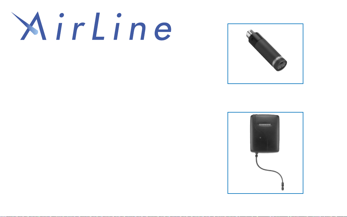
UHF Wireless System
Owners Manual
Handheld Tr ansmitter
Presentation
Transmitter
• AX1 Handheld Transmitter
• AL1 Presentation Transmitter
• AR1 Receiver
• UR1 Receiver
• UM1 Receiver
SAMSON

ENGLISH
Introduction 1
QuickStart 2
Guided Tour - AR1 Receiver 4
Guided Tour - UR1 Receiver 6
Guided Tour - UM1 Receiver 9
Guided Tour - AX1 Handheld Transmitter 12
Guided Tour - AL1 Presentation Transmitter 14
Setting Up and Using Your AirLine System 17
Specifications 81
Appendix A: Channel Plan 85
Appendix B: Attaching The Lanyard to the AL1 86
FRANCAIS
Introduction 21
Prise en main 22
Visite guidée – Récepteur AR1 24
Visite guidée – Récepteur UR1 26
Visite guidée – Récepteur UM1 29
Visite guidée – Emetteur main AX1 32
Visite guidée – Emetteur de presentation AL1 34
Configuration et utilisation des systèmes AirLine 37
Spécifications 81
Appendix A: Tableau de conversion de fréquence 85
Appendix B: Attaching The Lanyard to the AL1 86
Samson T echnologies Corp.
575 Underhill Blvd.
P.O. Box 9031
Syosset, NY 11791-9031
Phone: 1-800-3-SAMSON (1-800-372-6766)
Fax: 516-364-3888
Table of Contents
Produced by On The Right Wavelength for Samson Technologies Corp.
Copyright 2000, Samson Technologies Corp.
Printed August 2000
DEUTSCHE
Einleitung 41
Schneller Einstieg 42
Übersicht - Empfänger AR1 44
Übersicht - Empfänger UR1 46
Übersicht - Empfänger UM1 49
Übersicht - Hand-Sender AX1 52
Übersicht - Presentation-Sender AL1 54
Konfiguration und Betrieb der AirLine-Systeme 57
Technische Daten 81
Anhang A: Frequenzzuordnung der Empfangskanäle 85
Anhang B: Attaching The Lanyard to the AL1 86
ESPANOL
Introducción 61
Arranque rápido 62
Recorrido guiado – Receptor AR1 64
Recorrido guiado – Receptor UR1 66
Recorrido guiado – Receptor UM1 69
Recorrido guiado – Transmisor manual AX1 72
Recorrido guiado – Transmisor de presentation AL1 74
Ajuste y uso de su sistema AirLine 77
Especificaciones 81
Apéndice A: Tabla de conversión de frecuencias 85
Apéndice B: Attaching The Lanyard to the AL1 86

Welcome to Samson AirLine—the wireless system for the new millenium! Wireless microphone and instrument systems were
originally developed to eliminate cables, providing unparalleled freedom of movement. AirLine takes this concept to a new level with
transmitters so small, lightweight and aerodynamic, they are nearly invisible, providing a completely “hassle-free” user experience.
To create the world’s smallest wireless transmitters, we developed new proprietary technology. Featuring miniaturized circuitry and the
ability to operate on a single tiny AAA battery (with 14 hours typical battery life), these transmitters also feature significantly improved
wireless reception and sound quality. What’s more, the AR1 micro receiver developed especially for the AirLine system is actually
smaller than the typical wireless transmitter.
There are two different Samson AirLine systems detailed in this manual. Both operate in the 801 - 805 MHz UHF frequency range
and each contains an AR1 micro receiver or one of the receivers from our acclaimed Series One system—either a UR1 true diversity
receiver (for professional performance applications) or a UM1 micro diversity receiver (optimized for the production of professional
audio tracks to accompany your video shoot or live broadcast). The AirLine UHF Microphone System contains an AX1 hand-held
transmitter, which plugs into any standard wired dynamic microphone. The AirLine UHF Presentation System contains an AL1 pre-
sentation transmitter, which contains a built-in electret condenser microphone and connection for an optional lavalier microphone.
In this manual, you’ll find a more detailed description of the features of all AirLine systems, as well as a guided tour through all
components, step-by-step instructions for setting up your system and full specifications. If your AirLine system was purchased in the
United States, you’ll also find a warranty card enclosed—don’t forget to fill it out and mail it! This will enable you to receive online
technical support and will allow us to send you updated information about this and other Samson products in the future. If your
AirLine system was purchased outside of the U. S., contact your local distributor for warranty details. Also, be sure to check out our
website (http://www.samsontech.com) for complete information about our full product line.
SPECIAL NOTE for U.S. purchasers: Should your AirLine system ever require servicing, a
Return Authorization number (RA) is
necessary. Without this number, the unit will not be accepted. If your AirLine system was purchased in the United States, please call
Samson at 1-800-372-6766 for a Return Authorization number prior to shipping your system. If possible, return the unit in its original
carton and packing materials. If your AirLine system was purchased outside of the U. S., contact your local distributor for information.
1
Samson AirLine
Introduction
ENGLISH

If you’ve had some prior experience using wireless systems, these QuickStart instructions will get you up and running with your
AirLine system in a matter of minutes! Detailed instructions for setting up and using your AirLine system can be found on page 17 of
this manual, and the “Guided T our” sections on pages 4 - 16 provide full descriptions of all AirLine component controls and displays.
1. Make sure that the supplied receiver and AX1 or AL1 transmitter are factory preset to the same channel.
2. Physically place the receiver where it will be used (if desired, the AR1 receiver model can be wall-mounted using the supplied
holder) and extend its antenna(s) vertically.
3. Set the power switch to your transmitter to the “off” position (away from the arrow) and place a fresh battery in it. Then turn the
transmitter back on momentarily; its LED will flash once and then go off if the battery is sufficiently strong. Once battery strength is
verified, turn the transmitter off.
4. If you are using an AX1, plug its XLR connector into a wired dynamic microphone; make a good tight connection, using the
supplied rubber gasket if necessary. If you are using the AL1 with an external lavalier microphone, make the physical connection
between its input connector and the microphone.
5. Turn your audio system off and make the physical cable connection between the receiver’s balanced or unbalanced output jack
(if necessary, both can be used simultaneously) and a mic level audio input of your amplifier or mixer. If your system contains a UR1
or UM1 receiver, be sure to set its Audio Output Level switch correctly.
6. Turn the Volume, Level or AFLevel knob on the receiver completely counterclockwise. Connect the supplied AC adapter to the
receiver and plug it in (or place a fresh battery in the UM1 receiver), but leave its power off for the moment.
7. Turn on the receiver. If your system contains an AR1 or UR1 receiver, its “Power” LED will light steadily red. (Note: the UM1
2
Samson AirLine
QuickStart
ENGLISH

receiver has no such LED.)
8. Turn on your transmitter. If your system contains an AR1 receiver, its “Power/ RF” LED should change color from red to green, indi-
cating that it is receiving valid RF signal and is placed and positioned correctly. If your system contains either a UR1 or UM1 receiver,
one of the “A/B Receiver” LEDs will be lit, showing you whether the (left) “A” or (right) “B” receiver is currently being used. The UR1 /
UM1 meter will also indicate the strength of the incoming RF signal.
9. Turn on your connected amplifier and/or mixer but keep its volume all the way down. If your system contains an AL1 transmitter,
make sure it is unmuted. Set the Volume, Level or AF Level knob on the receiver fully clockwise; this is unity gain.
10. Speak or sing into your mic at a normal performance level while slowly raising the audio input control of your amplifier or mixer
until the desired level is reached. If necessary, use the supplied plastic screwdriver to adjust the transmitter’s Gain trimpot in order to
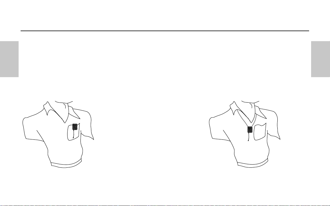
increase or decrease its signal level. If you are using an AL1 transmitter with the built-in microphone, correct placement is critical to
sound quality. It should be unobstructed by clothing and either clipped to a shirt pocket or lapel, or worn around the neck on the sup-
plied lanyard.
11. Do a walkaround through the intended area of coverage while observing the receiver’s “Power/RF” LED or RF Meter; it should
indicate sufficient RF reception in all areas of coverage (in the case of the AR1, the LED will light steadily green) . Reposition it (or its
antenna) as necessary. If extended range coverage is required, a Samson UR1 or UM1 true diversity receiver (set to the same channel
as the transmitter) should be used
12. If you hear any spurious noise from the receiver output when the transmitter is turned off, use the supplied plastic screwdriver to
adjust the receiver Mute (squelch) level control, slowly turning it clockwise to the point at which the noise disappears.
3
Samson AirLine
QuickStart
ENGLISH
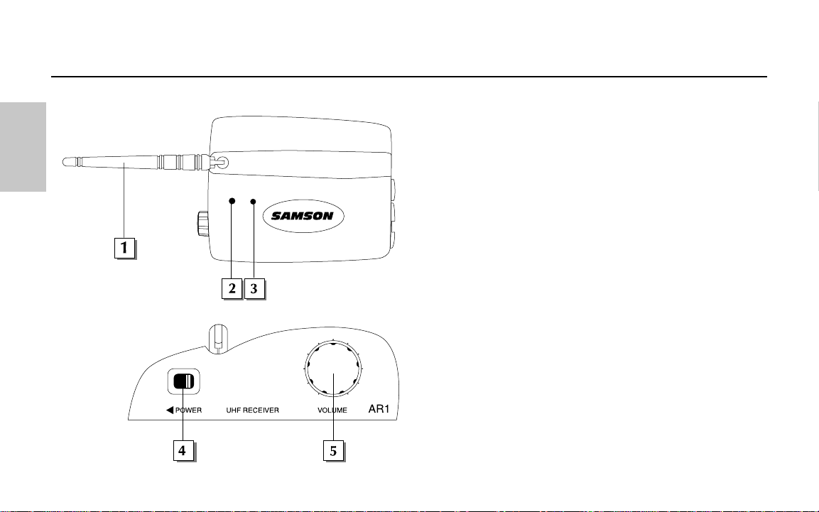
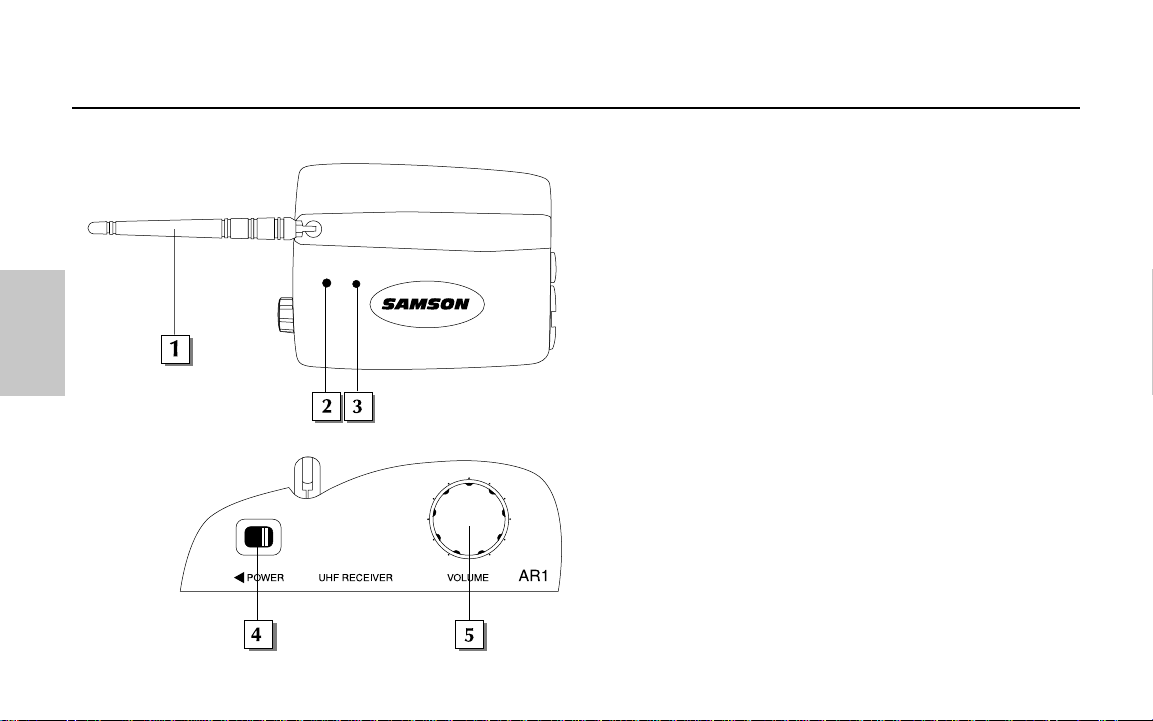
1: Antenna - This swivel mounting allows full rotation for
optimum placement of the antenna. In normal operation,
the antenna should be placed in a vertical position. It can
be folded inward for convenience when transporting the
AR1. See the “Setting Up and Using Your AirLine System”
section on page 17 in this manual for more information
about antenna positioning.
2: Power On / RF LED- This lights red whenever the AR1 is
powered on and green whenever the AR1 is receiving RF
signal from a transmitter.
3: Peak LED - This LEDlights red when output signal from
the AR1 is at the onset of clipping (that is, when it is on the
verge of being distorted). If you see this light during
operation, move the microphone further away or lower the
volume level of your instrument or transmitter. For more
information, see the section entitled “Setting Up and Using
Your AirLine System” on page 17 in this manual.
4: Power switch - Move this switch in the direction of the
arrow to turn power to the AR1 on; move it away from the
arrow to turn power off.
5: Volume control - This knob sets the level of the audio
signal being output through both the AR1 balanced and
unbalanced output jacks (see #6 and #7 on the following
page). Reference level is obtained when the knob is turned
fully clockwise.
4
Samson AirLine
Guided Tour - AR1 Receiver
ENGLISH
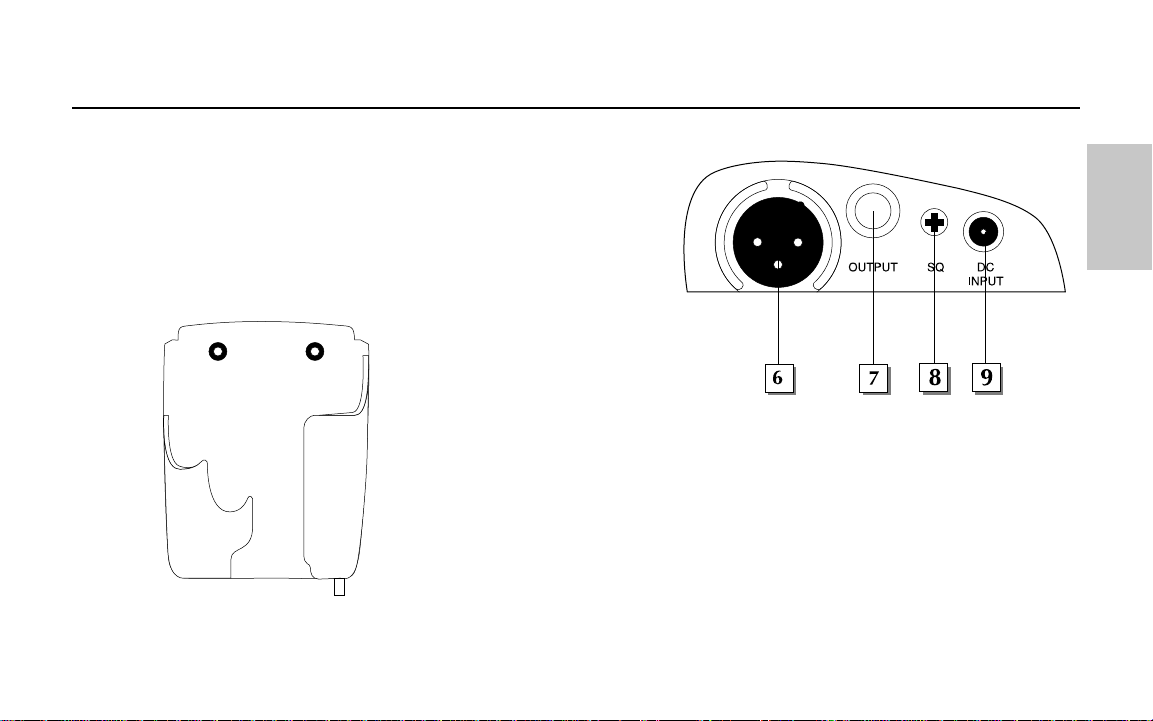
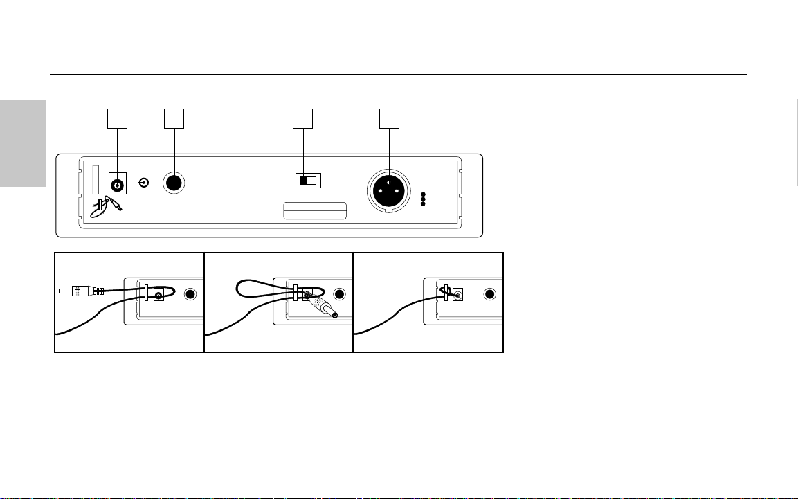
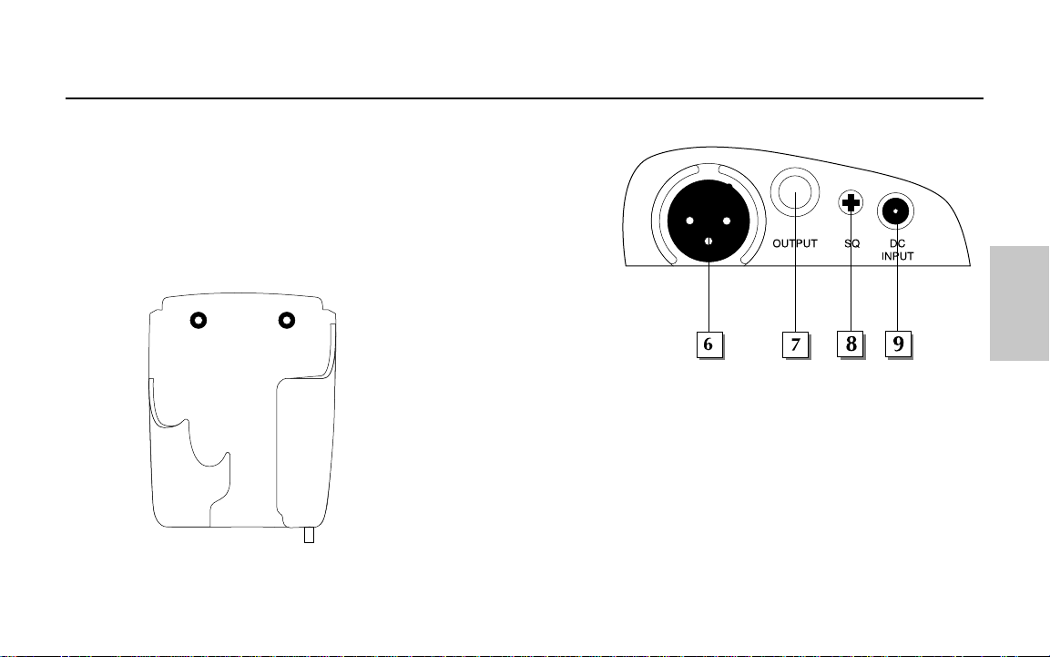
6: Unbalanced output* - Use this unbalanced high impedance
(5 - 10 K Ohm) 1/4" jack when connecting the AR1 to consumer
(-10) audio equipment. Wiring is as follows: tip hot, sleeve ground.
7: Balanced output* - Use this electronically balanced low
impedance (600 - 2500 Ohm) XLR jack when connecting the AR1
to professional (+4) audio equipment. Pin wiring is as follows:
Pin 1 ground, Pin 2 high (hot), and Pin 3 low (cold).
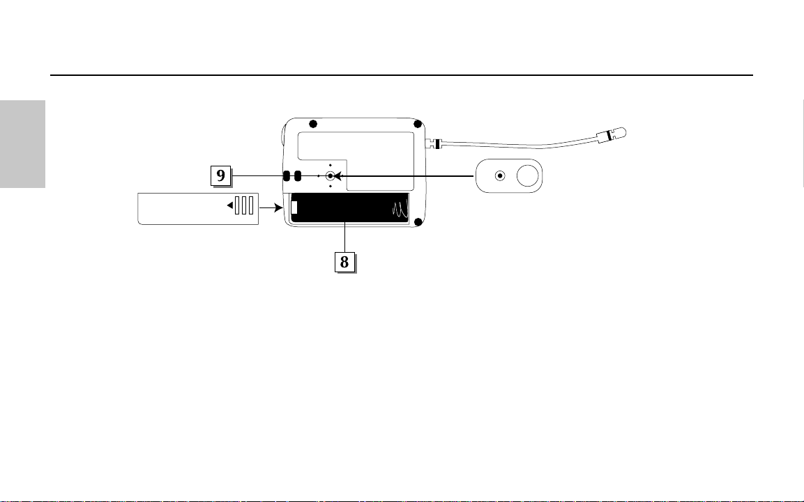
8: Mute (squelch) control -
This control determines the
maximum range of the AR1
before audio signal dropout.
Although it can be adjusted
using the supplied plastic
screwdriver, it should
normally be left at its factory setting. See the “Setting Up and Using Your AirLine System”
section on page 17 in this manual for more information.
9: DC input - Connect the supplied 12 volt 200 mA power adapter here.
WARNING: Do not substitute any other kind of power adapter; doing so can cause
severe damage to the AR1 and will void your warranty.
As shown in the illustration on the left, the supplied AR1 receiver holder can be used to
wall-mount the AR1 in fixed installations.
* If required, both the balanced and unbalanced outputs can be used simultaneously.
5
Samson AirLine
Guided Tour - AR1 Receiver
Wall-mount AR1 receiver holder
ENGLISH
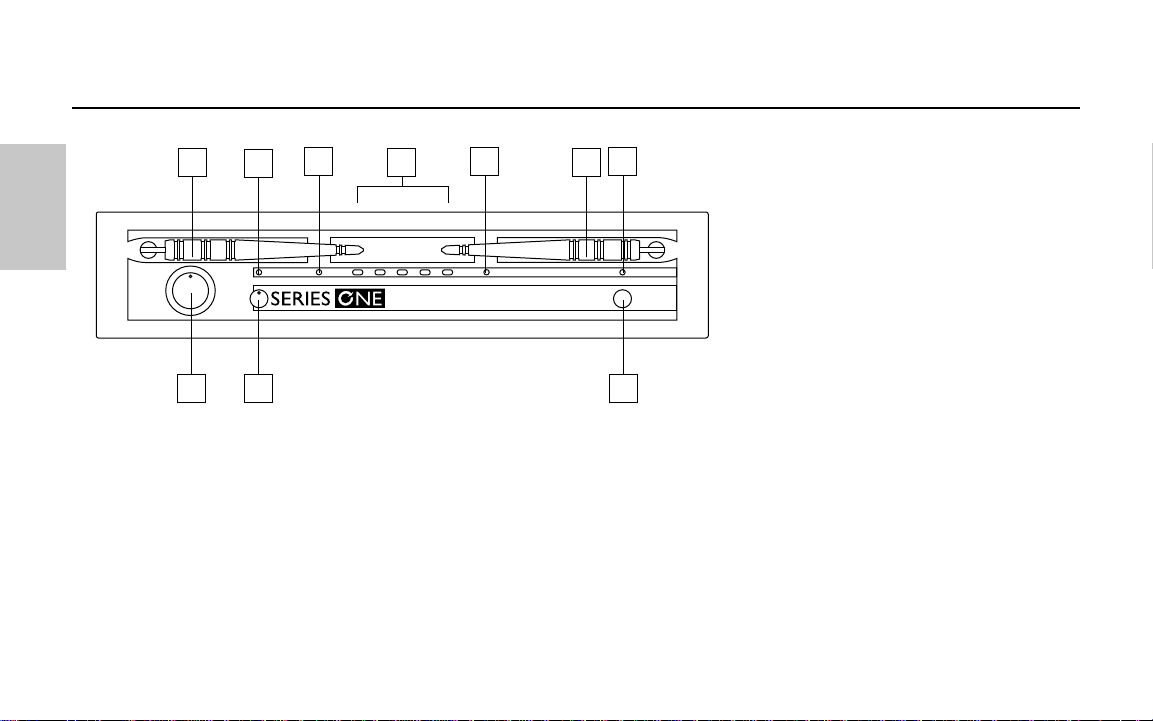
1: Antennas (A and B) - The
antenna mountings allow full
rotation for optimum placement.
In normal operation, both Antenna
A (the antenna on the left) and
Antenna B (the antenna on the
right) should be placed in a vertical
position. Both antennas can be
folded inward for convenience
when transporting the UR1. See
the “Setting Up and Using the
AirLine System” section on page
17 in this manual for information
about antenna installation and
positioning.
2: AF (Audio Frequency) Level control - This knob sets the level of the audio signal being output through both the balanced and
unbalanced output jacks on the rear panel (see #2 and #4 on page 8 in this manual). Reference level is obtained when the knob is
turned fully clockwise (to its “10” setting).
3: Peak LED - This LEDlights yellow when output signal from the UR1 is at the onset of clipping (that is, when it is on the verge of
being distorted). If you see this light during operation, move the microphone further away or lower the output level of your
instrument or transmitter. For more information, see the section entitled “Setting Up and Using the AirLine System” on page 17 in
this manual.
6
Samson AirLine
Guided Tour - UR1 Receiver / Front Panel
ENGLISH
SAMSON
UHF RECEIVER
1
2
3
5
1
7
4
4
6
8

4: A/B Receiver LEDs - When signal is being received, one of these will be lit green, showing you whether the (left) “A” or (right)“B”
receiver is currently being used. The UR1 constantly scans its two antennas and automatically selects whichever is receiving the
strongest, clearest signal. This
True Diversity switching is completely inaudible, but it effectively increases overall range while vir-
tually eliminating potential interference and phase cancellation problems.
5: RF (Radio Frequency) Level meter - This five-segment meter (similar to the VU bar meter used on audio devices) indicates the
strength of the UHF signal being received. When all segments are lit, the incoming RFsignal is at optimum strength; when only the
left-most segment is lit, the incoming RF signal is at minimum strength. If no segments are lit, no signal is being received; check to
ensure that the transmitter is on and that it is set to the same channel as the UR1. See the “Setting Up and Using the AirLine System”
section on page 17 in this manual for more information.
6: Power LED- This lights red whenever the UR1 is turned on.
7: Mute (squelch) control - This control determines the maximum range of the UR1 before audio signal dropout. Although it can be
adjusted using the supplied plastic screwdriver, it should normally be left at its factory setting. See the “Setting Up and Using the
AirLine System” section on page 17 in this manual for more information.
8: Power switch - Use this to turn the UR1 power on and off. When the receiver is on, the Power LED (see #6 above) is lit.
7
Samson AirLine
Guided Tour - UR1 Receiver / Front Panel
ENGLISH
1: DC input - Connect the supplied
12 volt 160 mA power adapter here,
using the strain relief as shown in the
illustration below.
WARNING: Do not
substitute any other kind of power
adapter; doing so can cause severe
damage to the UR1 and will void your
warranty.
2: Unbalanced output* - Use this
unbalanced high impedance (5K
Ohm) 1/4" jack when connecting the
UR1 to consumer (-10) audio
equipment. Wiring is as follows:
tip hot, sleeve ground.
3: Audio Output Level switch - Sets
the audio output level attenuation of
the balanced output (see #4 below) to
-20 dBm (line level) or -40 dBm
(mic level). See “Setting Up and
Using the AirLine System” on page 17.
4: Balanced output* - Use this electronically balanced low impedance (600 Ohm) XLR jack when connecting the UR1 to professional
(+4) audio equipment. Pin wiring is as follows: Pin 1 ground, Pin 2 high (hot), and Pin 3 low (cold).
* If required, both the unbalanced and balanced outputs can be used simultaneously.
8
Samson AirLine
Guided Tour - UR1 Receiver / Rear Panel
ENGLISH
UNBALANCED
OUTPUT
BALANCED SWITCH
BALANCED OUTPUT
XLR:
1 GND
2 HOT
3 COLD
LINE:
-20dBm600Ω
MIC:
-40dBm600Ω
MIC
LINE
POWER RATING
DC 12V, 1.9W(160mA)
-10dB 5KΩ
DC INPUT
1
2
3
4
+
-
AC CABLE LOCK
CAUTION:
USE SAMSON
AC ADAPTOR
ONLY
CABLE LOCK: LOOP THRU AND TIE
-
Using the strain relief: Gather up a loop of wire and pass it through the strain relief,
then pass the adapter plug through the loop in order to create a knot.
1: A/B Receiver LEDs - When signal is being received, one of these will be lit
orange, showing you whether the (left) “A” or (right) “B” receiver is currently being
used. The UM1 constantly scans its two antennas and automatically selects
whichever is receiving the strongest, clearest signal. This True Diversity switching
is completely inaudible, but it effectively increases overall range while virtually
eliminating potential interference and phase cancellation problems.
2: Meter - This set of three multicolor LEDs acts as a meter, indicating either bat-
tery power or the strength of the incoming RF signal. This meter can also be dis-
abled altogether to conserve battery power. See #15 on page 11 for more
information.
3: Peak LED - This LEDlights red when output signal from the UM1 is at the onset
of clipping (that is, when it is on the verge of being distorted). If you see this light
during operation, move the microphone further away or lower the output level of
your instrument or transmitter. For more information, see the section entitled
“Setting Up and Using the AirLine System” on page 17 in this manual.
4: Power switch - Use this to turn the UM1 power on and off.
5: SQ (Squelch) Level control - This control determines the maximum range of the
UM1 before audio signal dropout. Although it can be adjusted using the supplied
plastic screwdriver, it should normally be left at its factory setting. See the “Setting
Up and Using the AirLine System” section on page 17 in this manual for more
information.
9
Samson AirLine
Guided Tour - UM1 Receiver
SAMSON
SAMSON
MAX
MIN
POWER
ON
SQ LEVEL
UHF MICRO DIVERSITY RECEIVER
B
A
LOW MID HIGH PEAK
800MHz
2 3 1
5
7
4
6
1
+
-
ENGLISH
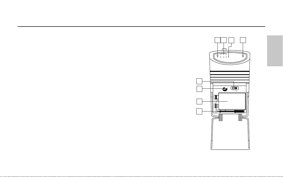
6: Battery holder - Insert a standard 9-volt alkaline battery here, being sure to
observe the plus and minus polarity markings shown. We recommend the
Duracell MN 1604 type battery. Although rechargeable Ni-Cad batteries can be
used, they do not supply adequate current for more than four hours.
WARNING: Do not insert the battery backwards; doing so can cause severe
damage to the UM1 and will void your warranty.
7: Plastic screwdriver - Specially designed for use in adjusting the UM1 Squelch
Level control (see #4 on the previous page). See the “Setting Up and Using the
AirLine System” section on page 17 in this manual for more information.
8: Antennas (A and B) - The antenna mountings allow full rotation for optimum placement. In normal operation, both antennas
should be placed in a vertical position. Both antennas can be folded inward for convenience when transporting the UM1. See the
“Setting Up and Using the AirLine” section on page 17 in this manual for more information.
9: DC input - This jack will accept a DC input voltage of 6 - 13 volts (inner connection [tip] positive, outer connection [sleeve]
ground) from your video camera, if available. Connect an optional Samson AC300R adapter here to charge a rechargeable 9-volt
Ni-Cad battery.
10: Unbalanced output* - Use this unbalanced (1K Ohm max.) 1/8" (3.5 mm) mini-phone jack when connecting the UM1 to
consumer (-10) audio equipment. Wiring is as follows: tip hot, sleeve ground. If your video camera has stereo audio inputs, you’ll
need to use a Y-adapter that has a 1/8" (3.5 mm) mini-phone plug at one end and dual male RCA-type plugs at the other end.
11: Audio Output Level switch - Sets the audio output level of both the balanced and unbalanced outputs (see #10 above and #14
10
Samson AirLine
Guided Tour - UM1 Receiver
30 20 10
LEVELOUT UNBAL
DC INPUT
109 118
ENGLISH
on the following page) to -30 dBm (mic level), -20 dBm, or -10 dBm (line level).
See the “Setting Up and Using the AirLine System” section on page 17 in this
manual for more information.
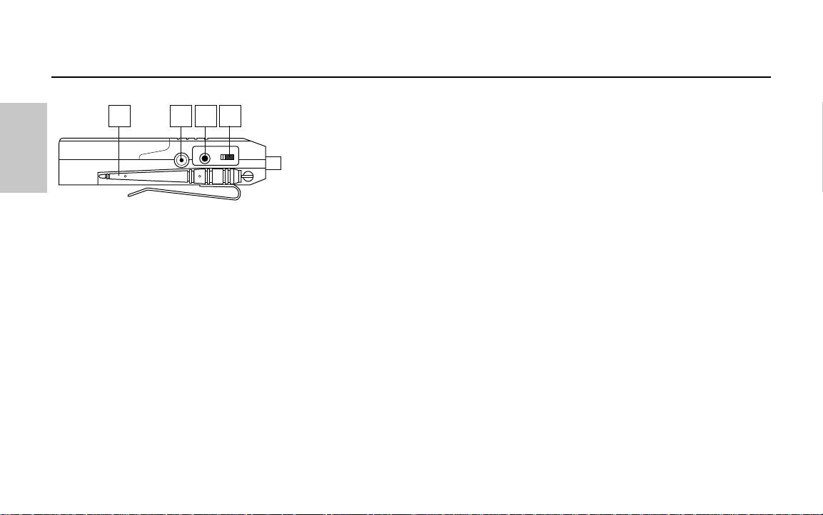
12: Level control - This knob sets the level of the audio signal being sent to the
headphones output (see #13 below).
13: Headphones output - Connect a stereo headphone to this standard 1/8"
(3.5 mm) mini-phone jack in order to monitor the signal being output by the UM1.
We recommend the use of 30 ohm headphones. The level of the headphone signal can be set by adjusting the Level control (see
#12 above). Maximum output is 240 mW @ 30 ohms).
14: Balanced output* - Use this electronically balanced low impedance (600 Ohm) mini-XLR jack when connecting the UM1 to
professional (+4) audio equipment. Pin wiring is as follows: Pin 1 ground, Pin 2 high (hot), and Pin 3 low (cold).
15: Meter switch - This three-position switch determines the function of the front-panel UM1 meter (see page #2 on page 9). In
the left “RF” position, the meter indicates the strength of the incoming RF signal. In the center “BATTERY”position, the meter indi-
cates relative battery power, showing whether the installed battery is at low (red), mid (yellow) or high (green) strength. (Note:
When the red “low” indicator lights, performance is degraded and the battery needs to be replaced). In the right “OFF” position,
the meter is disabled altogether, thus conserving battery power.
* If required, both the unbalanced and balanced outputs can be used simultaneously.
11
Samson AirLine
Guided Tour - UM1 Receiver
PHONES
LEVEL
O
U
T
P
U
T
B
A
L
A
N
C
E
D
METER
RF OFF
12
13
14
15
BATT.
ENGLISH
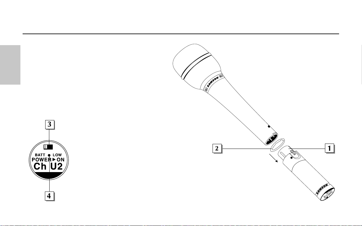
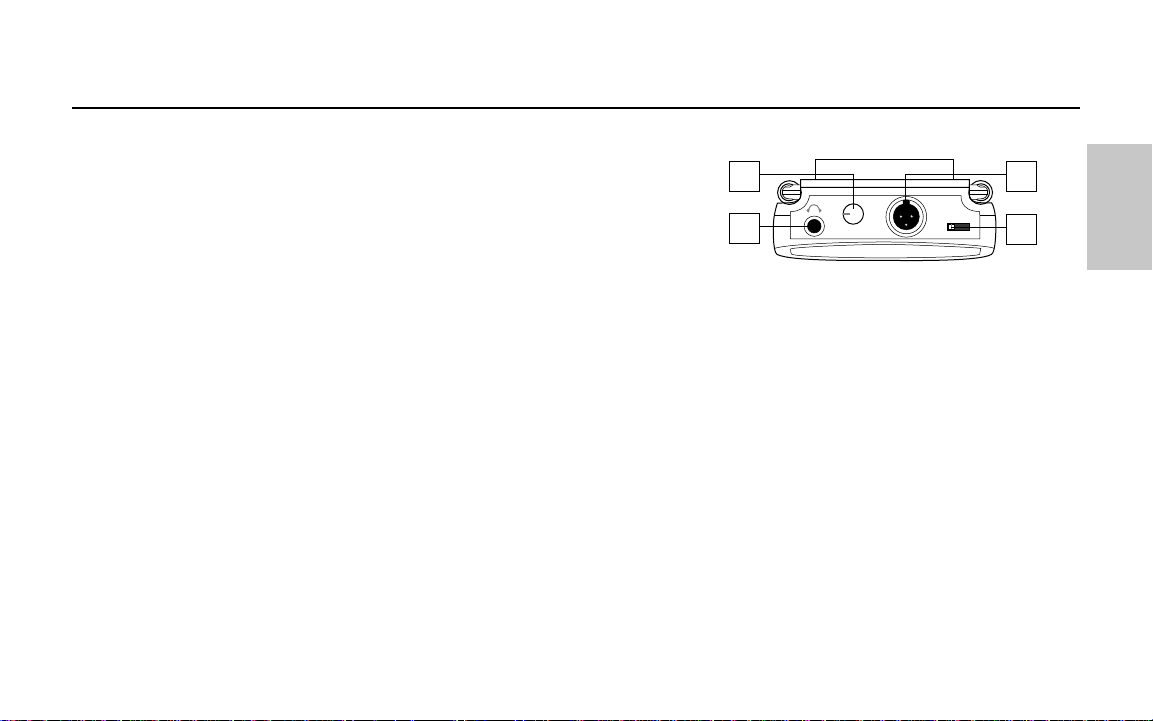
1: XLR connector - Connect this standard female XLR connector
into any standard wired dynamic microphone in order to make it
a wireless mic.
2: Rubber gasket - If necessary, use this provided rubber gasket
in order to make a solid connection between the AX1 XLR
connector and your microphone (note that not all microphones
require its use).
3: Power on-off switch - Move this switch in the direction of the
arrow to turn power to the AX1 on; move it away from the arrow
to turn power off. (to conserve
battery power, be sure to turn the
AX1 off when not in use). Be sure
to mute the audio signal at your
external mixer or amplifier before
turning the AX1 power on or off, or
an audible pop may result.
4: Power / Battery LED - This LED
flashes once when the AX1 is first
turned on and lights steadily red
when there is less than 2 hours of
battery power remaining, indicating
that the battery needs to be
12
Samson AirLine
Guided Tour - AX1 Handheld T ransmitter
ENGLISH
changed.
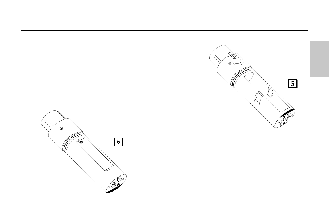
5: Battery compartment - Insert a standard AAA alkaline battery here,
being sure to observe the plus and minus polarity markings shown. We
recommend the Duracell type battery. Although rechargeable Ni-Cad
batteries can be used, they do not supply adequate current for more than
four hours.
WARNING: Do not insert the battery backwards; doing so can
cause severe damage to the AX1 and will void your warranty.
6: Microphone Input Level control (trimpot) - Use the supplied plastic
screwdriver to raise or lower the input level sensitivity of the AX1 as required.
See the “Setting Up and Using Your AirLine System” section on page 17 in
this manual for more information.
13
Samson AirLine
Guided Tour - AX1 Handheld T ransmitter
+
_
A
F LE
V
E
L
M
IN
M
A
X
ENGLISH
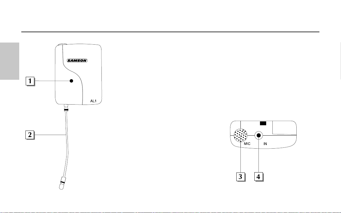
1: Power / Battery LED - This LED flashes once when the AL1 is first turned on and lights
steadily red when there is less than 2 hours of battery power remaining, indicating that the
battery needs to be changed.
2: Antenna - This permanently attached flexible antenna should be fully extended during
normal operations. See the “Setting Up and Using Your AirLine System” section on page 17
in this manual for more information about antenna positioning.
3: Electret condenser microphone - This high- quality unidirectional electret condenser
microphone with metal windscreen is optimized for clear, crisp reproduction of speech.
It is active whenever the AL1 is powered on, as long as there is no connection made to the
lavalier microphone input connector (see #4 below). When a plug is inserted into the
lavalier microphone input connector, this built-in microphone is muted.
4: Lavalier microphone input connector - Use this
standard 2.5 mm mini-jack if you want to connect
an external lavalier microphone to the AL1.
Note that, because the AL1 has a built-in electret
condenser microphone (see #3 above), the use of an
external lavalier mic is optional and not required.
The AL1 provides 2.7V of phantom power, so
condenser mics can be used if desired.
14
Samson AirLine
Guided Tour - AL1 Presentation T ransmitter
ENGLISH
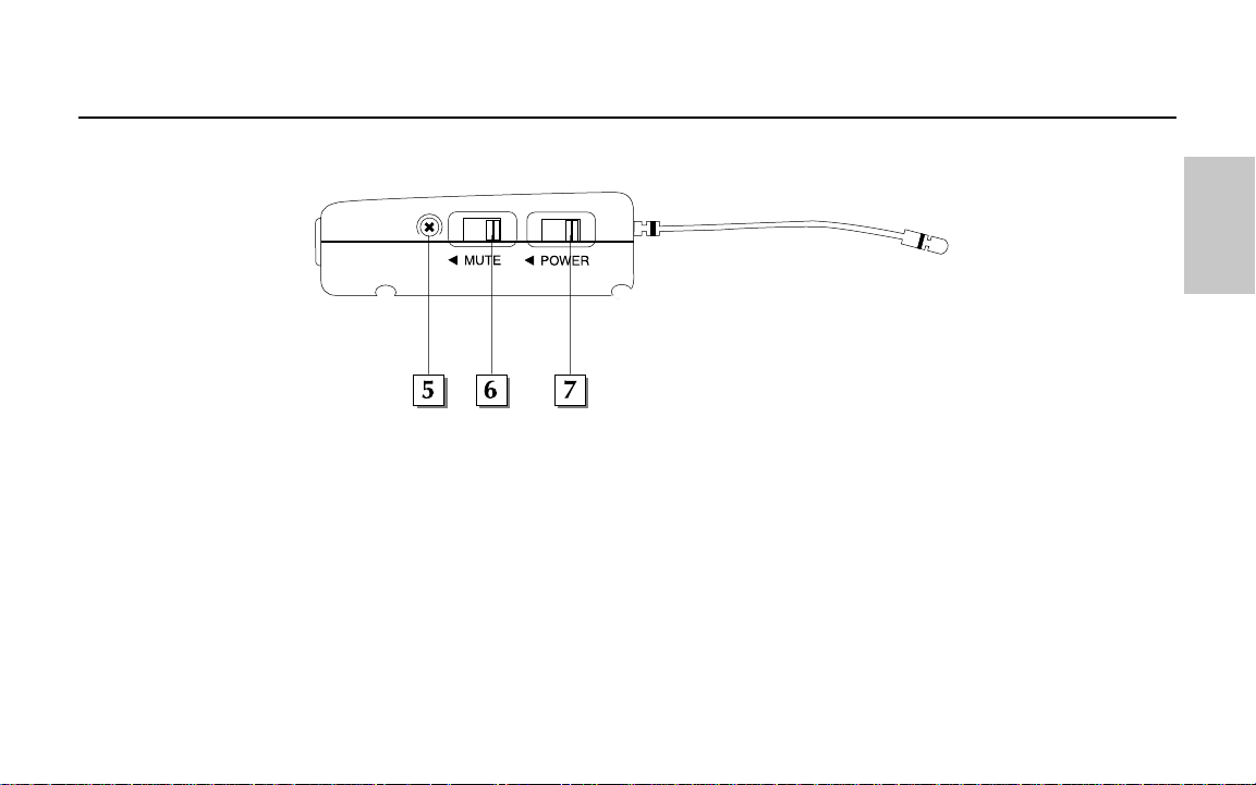
5: Gain control (trimpot) - Use the supplied plastic screwdriver to raise or lower the input level sensitivity of the AL1 as required. See
the “Setting Up and Using Your AirLine System” section on page 17 in this manual for more information.
6: Mute switch - Move this switch in the direction of the arrow to mute the AL1; move it away from the arrow to unmute it and
transmit audio signal
. Because the carrier signal remains during muting, no “pop” or “thud” will be heard. Note that turning this off
does
not turn off the transmitter power—it is simply a way to temporarily mute the transmission of audio signal. If you don’t plan on
using the AL1 for extended periods, turn it off power by using the power on-off switch (see #7 below). Be sure to mute the audio
signal at your external mixer or amplifier before turning the AL1 power on or off, or an audible pop may result.
7: Power switch - Move this switch in the direction of the arrow to turn power to the AL1 on; move it away from the arrow to turn
power off. (to conserve battery power, be sure to turn the AL1 off when not in use).
15
Samson AirLine
Guided Tour - AL1 Presentation T ransmitter
GAIN
ENGLISH
8: Battery compartment - Insert a standard AAA alkaline battery here, being sure to observe the plus and minus polarity markings
shown. We recommend the Duracell type battery. Although rechargeable Ni-Cad batteries can be used, they do not supply adequate
current for more than four hours.
WARNING: Do not insert the battery backwards; doing so can cause severe damage to the AL1
and will void your warranty.
9: Clip connector - This clip can be used to fasten the AL1 to a lapel or shirt pocket or to the supplied lanyard. The position of the
clip can be rotated to the desired position after loosening its center screw or can be removed entirely by removing the center screw.
For more information on positioning the AL1, see the “Setting Up and Using the AirLine System” section on page 17 and Appendix B
on page 86 in this manual.
16
Samson AirLine
Guided Tour - AL1 Presentation T ransmitter
+
_
ENGLISH

17
Samson AirLine
The basic procedure for setting up and using your AirLine System takes only a few minutes:
1. For your AirLine system to work correctly, both the receiver and transmitter must be set to the same channel. Remove all packing
materials (save them in case of need for future service) and check to make sure that the supplied receiver and transmitter are set to the
same channel (a complete channel plan is printed on the inside back cover of this manual). If these channels do not match, contact
your distributor or, if purchased in the United States, Samson Technical Support at 1-800-372-6766.
2. Physically place the receiver where it will be used (the general rule of thumb is to maintain “line of sight” between the receiver and
transmitter so that the person using or wearing the transmitter can see the receiver). The AR1 can be mounted on a wall if desired,
using the supplied wall mount holder. The UR1 can be rack-mounted if desired (taking a half-rack space), using an optional Samson
adapter kit. The UM1 can be mounted to a video camera using the supplied velcro.
3. Extend the receiver antenna(s) and place it (them) in a vertical position. Make sure the Power on-off switch in your transmitter is
set to “Off.”
4a. If your system contains an AX1 handheld transmitter, unscrew the bottom section by turning it counterclockwise and then slide it
off.
4b. If your system contains an AL1 body pack transmitter, turn it over and slide off the battery door.
5. Place a fresh AAA alkaline battery in the transmitter battery compartment, taking care to observe the polarity markings. If you are
using an AX1 transmitter, replace the bottom section by sliding it on and then screwing it back on. If you are using an AL1 transmitter,
replace the battery door by sliding it in until it clicks. Whichever transmitter you are using, leave it off for the moment.
6. Make the physical cable connection between the receiver output jack and a mic level audio input of your amplifier or mixer.
The balanced XLR jack is preferable, since it will deliver an electromagnetically cleaner signal. If required, both the balanced and
unbalanced outputs can be used simultaneously. If your system contains a UR1 or UM1 receiver, be sure to set its Audio Output Level
switch correctly (see pages 8 and 10 for details). Leave your amplifier (and/or mixer) off at this time.
7. Turn the Volume, Level or AF Level knob on the receiver completely counterclockwise. Connect the supplied AC adapter to the
Setting Up and Using Your AirLine System
ENGLISH
18
Samson AirLine
AR1 or UR1 receiver and plug it in (the UM1 receiver can also operate off battery power or a 12 volt power supply from a connected
video camera), then plug the adapter into any standard AC outlet. Slide the Power switch in the direction of the arrow to turn on the
receiver. If your system contains an AR1 receiver, its “Power/ RF” LED will light steadily red; if your system contains a UR1 receiver,
its “Power” LED will light steadily red. (Note: The UM1 receiver has no “Power” LED indicator.)
8. Turn on the power to your transmitter (using its Power on-off switch); the “Power/Battery” LED will flash if the battery is sufficiently
strong (if it lights steadily, the battery has less than 2 hours of power remaining and should be replaced). If your system contains an
AR1 receiver, its “Power/ RF” LED on the receiver should change color from red to green, indicating that it is receiving valid RF signal
and is placed and positioned correctly. If your system contains either a UR1 or UM1 receiver, one of the “A/B Receiver” LEDs will
light, showing you whether the (left) “A” or (right) “B” receiver is currently being used. The UR1 / UM1 meter will also indicate the
strength of the incoming RF signal.
9. Now it’s time to set the audio levels. Turn on
your connected amplifier and/or mixer but keep its
volume all the way down. If you are using an AL1
transmitter, make sure that it is unmuted (its Mute
switch should be positioned away from the arrrow).
Then set the Volume, Level or AF Level knob on the
receiver fully clockwise; this is unity gain. If
you are using an AL1 transmitter with the built-in
microphone, note that correct placement is critical
to sound quality. We recommend that you place it
as shown in the illustrations on this page—
unobstructed by clothing and either clipped to a
shirt pocket or lapel, or worn around the neck on the supplied lanyard.
Setting Up and Using Your AirLine System
SAMSON
SAMSON
ENGLISH
ENGLISH

19
Samson AirLine
10. Speak or sing into your mic at a normal performance level while slowly raising the volume of your amplifier and/or mixer until
the desired level is reached. The UM1 receiver allows you to monitor the transmission signal using standard Walkman-type 30 ohm
headphones connected to its headphone jack. Note that
Unidirectional microphones (mics which pick up signal from just one
direction) such as the built-in AL1 electret condenser are less prone to feedback than other types of mics. Any feedback problems you
encounter can be minimized by being sure not to use the microphone directly in front of a PA speaker or by using an equalizer to
attenuate (reduce) those high- or mid-range frequencies which are causing the feedback “squealing”.
11. If you hear distortion at the desired volume level, first check to see whether the “Peak” LED on the receiver is lit. If it is
not lit,
make sure that the gain structure of your audio system is correctly set (consult the owners manual of your mixer and/or amplifier for
details). If the red “Peak” LED
is lit, do the following:
• If you are using an AX1 transmitter, use the supplied plastic screwdriver to turn its Microphone Input Level control (trimpot)
slowly counterclockwise (towards the “Min” position) until the distortion disappears.
• If you are using an AL1 transmitter with its internal electret condenser microphone, simply move the microphone further from
your mouth. If you are using an AL1 with an external lavalier microphone, use the supplied plastic screwdriver to turn the Gain
control (trimpot) slowly counterclockwise until the distortion disappears.
12. Conversely, if you hear a weak, noisy signal at the desired volume level, again make sure that the gain structure of your audio
system is correctly set (consult the owners manual of your mixer and/or amplifier for details) and that the Volume control of the
receiver is fully clockwise. If it
is lit and the signal coming from the receiver is still weak and/or noisy, do the following:
• If you are using an AX1 transmitter, use the supplied plastic screwdriver to turn its Microphone Input Level control (trimpot)
slowly clockwise (towards the “Max” position) until the signal reaches an acceptable level.
• If you are using an AL1 transmitter with its internal electret condenser microphone, simply position the microphone closer to
your mouth. If you are using an AL1 with an external lavalier microphone, use the supplied plastic screwdriver to turn the Gain
control (trimpot) slowly clockwise until the signal reaches an acceptable level.
Setting Up and Using Your AirLine System
ENGLISH

20
Samson AirLine
13. Temporarily turn down the level of your mixer/amplifier system and turn off the power to your transmitter, leaving the receiver on.
Then restore the previously set level of your mixer/amplifier. With the transmitter off, the receiver output should be totally silent—if it
is, skip ahead to the next step. If it isn’t (that is, if you hear some noise), you may need to adjust the receiver Mute (squelch) control.
When the Mute control is at its minimum setting, the AirLine system always provides maximum range without dropout; however,
depending upon the particular environment your system is used in, you may need to reduce that range somewhat in order to eliminate
band noise when the transmitter is turned off. To do so, use the provided screwdriver to rotate the Mute (squelch)control completely
counterclockwise (to the “Min” position), then slowly turn it clockwise until the noise disappears. If no noise is present at any
position, leave it at its fully counterclockwise “Min” position (so as to have the greatest overall range available).
14. When first setting up your AirLine System in a new environment, it’s always a good idea to do a walkaround in order to make sure
that coverage is provided for your entire performance area. Accordingly, turn down the level of your audio system and turn on both
the transmitter and receiver. Then, with the transmitter unmuted, restore the level of your audio system and while speaking or singing,
walk through the entire area that will need to be covered. As you do so, observe the RF display or meter on the receiver to make sure
that it is receiving sufficiently strong RF signal (in the AR1 receiver, the “Power On / RF” LED should always remain lit steadily green;
in the UR1 and UM1 receivers, all segments of the RF Level meter should be lit). Always try to minimize the distance between trans-
mitter and receiver as much as possible so that the strongest possible signal is received from all planned transmission points. If you are
using an AR1 receiver in fixed installations such as A/V or corporate conference rooms, you may find it handy to mount it in the sup-
plied wall-mount holder. In certain environments, it may be desirable to angle the receiver antenna(s) differently from the vertical
position. Where extended range coverage is required, the Samson UR1 true diversity receiver (set to the same channel as the trans-
mitter) should be used. For videography applications, the Samson UM1 micro diversity receiver should be used.
If you have followed all the steps above and are experiencing difficulties, contact your local distributor or, if purchased in the
United States, call Samson Technical Support (1-800-372-6766) between 9 AM and 5 PM EST.
Setting Up and Using Your AirLine System
ENGLISH

Bienvenue sur Samson Airline. Envolez-vous vers la liberté grâce aux systèmes sans fil du nouveau millénaire ! Les microphones et
instruments sans fil ont été inventés pour offrir aux musiciens et aux interprètes une liberté de mouvement totale. La gamme AirLine
reprend ce concept et le porte à une dimension encore jamais égalée grâce à des émetteurs si petits, légers et aérodynamiques qu'ils
sont quasiment invisibles ! Nous avons développé une toute nouvelle technologie qui a permis de créer des émetteurs aussi
miniatures. Dotés de circuits miniaturisés et fonctionnant sur une simple pile AAA (autonomie moyenne de 14 heures), ces émetteurs
bénéficient d'une qualité sonore et d'une qualité de réception vraiment améliorées. Qui plus est, le récepteur micro AR1 conçu
spécifiquement pour le système AirLine est en fait plus petit que l'émetteur sans fil !
Le présent mode d'emploi vous donne tous les renseignements nécessaires concernant deux modèles de la gamme Samson AirLine.
Tous deux fonctionnent dans la bande de fréquences UHF 801 à 805 MHz et reprennent le récepteur micro AR1 ou l'un des
récepteurs de la célèbre gamme Series One : soit un récepteur UR1 True Diversity (destiné aux applications professionnelles sur
scène), soit un récepteur UM1 Diversity (optimisé pour la production d'enregistrements audio pour des plateaux de vidéo ou de
diffusion en direct). Le système AirLine UHF Microphone se compose d'un émetteur main AX1 à relier à n'importe quel microphone
dynamique standard. Le système AirLine UHF Presentation comprend un émetteur AL1 équipé d'un microphone à condensateur à
électret et d'un port pour connexion sur un microphone cravate disponible en option.
Ce mode d'emploi présente les caractéristiques et possibilités détaillées des systèmes de la gamme AirLine, les procédures
d'utilisation ainsi que les caractéristiques techniques des appareils. Vous pouvez également y trouver une carte de garantie –
n'oubliez pas de la remplir et de nous la renvoyer pour pouvoir bénéficier de notre assistance technique en ligne et être informé des
dernières nouveautés Samson. Consultez également notre site Internet à l'adresse http://www.samsontech.com.
NOTE : En cas de panne, contactez votre revendeur Samson. Veuillez à cet effet conserver le carton et les emballages d'expédition
de l'appareil.
21
Samson AirLine
Introduction
FRANÇAIS

Si vous êtes un habitué des systèmes sans fil, ce chapitre vous permettra de régler et d'utiliser votre système AirLine en quelques
minutes ! Vous pouvez trouver les procédures de configuration et d'utilisation détaillées de votre système AirLine en page 37 de ce
mode d'emploi, ainsi que des "visites guidées" présentant les différentes commandes, connecteurs et témoins des modèles AirLine aux
pages 24 à 36.
1. Vérifiez que le récepteur et que l'émetteur AX1 ou AL1 fournis sont bien réglés sur le même canal.
2. Placez le récepteur à l'endroit où il devra être utilisé (le récepteur AR1 peut éventuellement être fixé à une cloison au moyen du
support mural fourni) et déployez son antenne.
3. Placez l'émetteur hors tension en plaçant l'interrupteur d'alimentation en position "Off" (pas sur la flèche), puis placez-y une pile
neuve. Faites alors repasser temporairement l'émetteur sous tension ; son témoin lumineux clignote alors une fois, puis s'éteint si la
pile est suffisamment puissante. Une fois que la puissance de la pile a été vérifiée, mettez l'émetteur hors tension.
4. Si vous utilisez un AX1, reliez un microphone dynamique à sa fiche XLR. Si nécessaire, assurez la connexion au moyen du joint en
caoutchouc fourni. Si vous utilisez un AL1 avec un microphone cravate externe, reliez le microphone à la fiche d'entrée du premier.
5. Placez votre système d'écoute hors tension, puis reliez la sortie symétrique ou asymétrique du récepteur (les deux sorties peuvent
être employés simultanément si besoin est) à l'une des entrées micro audio de votre amplificateur ou de votre console de mixage. Si
votre système est équipé d'un récepteur UR1 ou UM1, vérifiez que son sélecteur de niveau de sortie est correctement réglé.
6. Tournez le potentiomètre Volume, Level ou AF Level du récepteur complètement vers la gauche. Reliez l'une des extrémités de
l'adaptateur secteur fourni au récepteur et l'autre à une prise secteur (ou placez une pile neuve dans le récepteur UM1). Laissez le
22
Samson AirLine
Prise en main
FRANÇAIS

récepteur hors tension pour l'instant.
7. Placez le récepteur sous tension. Si votre système est pourvu d'un récepteur AR1 ou UR1, son témoin "Power" doit alors s'allumer
en rouge. Note : Le récepteur UM1 n'est doté d'aucun témoin de ce type.
8. Placez l'émetteur sous tension. Si vous êtes équipé d'un récepteur AR1, le témoin "Power/ RF" de l'AR1 doit alors virer au vert, ce
qui indique qu'il reçoit un signal HF valide et qu'il est correctement positionné. Si vous êtes équipé d'un récepteur UR1 ou UM1, l'un
des témoins "A/B Receiver" doit s'allumer, ce qui indique que l'un des deux canaux (gauche "A" ou droit "B") est en cours d'utilisation.
L'afficheur de niveau des UR1/UM1 vous renseigne par ailleurs sur l'intensité du signal HF reçu.
9. Allumez ensuite l'amplificateur ou la console de mixage utilisé(e) sans pour autant relever le volume. Vérifiez que l'émetteur AL1
n'est pas coupé par la fonction Mute. Tournez alors le potentiomètre Volume, Level ou AF Level du récepteur complètement sur la
droite, position qui correspond au gain unitaire.
10. Chantez ou prononcez des mots dans le micro au niveau auquel ils devront l'être lors du concert ou de la conférence tout en
relevant progressivement le niveau de l'entrée audio de l'amplificateur ou de la console de mixage jusqu'au volume souhaité. Si
nécessaire, baissez ou relevez le gain de l'émetteur via le potentiomètre Gain. Si vous utilisez un émetteur AL1 avec son microphone
interne, un bon placement est indispensable à une bonne qualité sonore. Veillez à ne pas le couvrir par un vêtement. Il doit être agrafé
sur une poche de chemise ou une cravate, ou être porté en pendentif grâce au cordon fourni.
11. Faites quelques pas sur toute la zone à couvrir tout en observant le témoin "Power/RF" ou l'afficheur de niveau HF (RF Meter) du
récepteur. Ce témoin (ou afficheur) doit toujours rester allumé en vert dans toutes les zones de couverture. Repositionnez, si
nécessaire, son ou ses antennes. Si vous avez besoin d'une plus grande couverture, remplacez l'AR1 par un récepteur True Diversity
Samson UR1 ou UM1 (réglé sur le même canal).
23
Samson AirLine
Prise en main
FRANÇAIS
12. Si vous entendez des émissions parasites à la sortie du
récepteur lorsque l'émetteur est hors tension, relevez pro-
gressivement le potentiomètre Mute (Squelch) du récepteur
jusqu'à ce que les interférences disparaissent.
24
Samson AirLine
Visite guidée – Récepteur AR1
FRANÇAIS
1: Antenne – L'antenne peut pivoter pour un placement optimal. En
conditions d'utilisation normales, laissez l'antenne à la verticale.
Vous pouvez toutefois l'incliner lors du transport de l'AR1. Vous
pouvez trouver de plus amples renseignements sur le positionnement
de l'antenne à la section "Configuration et utilisation de votre sys-
tème AirLine" en page 37 de ce mode d'emploi.
2: Témoin Power On/RF – Ce témoin s'allume en rouge à la mise
sous tension de l'AR1 et passe au vert lors de la réception de signaux
HF transmis par un émet-
teur.
3: Témoin Peak - Ce témoin
s'allume en rouge lorsque le
signal de sortie de l'AR1 est
proche de la saturation. Si
ce témoin s'allume en cours d'utilisation, éloignez le microphone de la source sonore ou
abaissez le volume de votre instrument ou de l'émetteur. Voir section "Configuration et utilisa-
tion des systèmes AirLine" en page 37 de ce mode d'emploi pour obtenir de plus amples ren-
seignements.
4: Interrupteur d'alimentation – Le fait de placer cet interrupteur sur la flèche met l'AR1
sous tension ; placez-le en position inverse pour le mettre hors tension.
5: Potentiomètre V olume – Ce potentiomètre permet de régler le niveau du signal audio
dirigé vers les sorties symétrique et asymétrique de l'AR1 (voir n°6 et n°7 de la page suivante).
Le fait de tourner ce potentiomètre à fond à droite cale l'AR1 sur le niveau de référence.
6: Sortie asymétrique* - Sortie haute impédance (5 - 10 kOhms) asymétrique sur Jack6,35mm
25
Samson AirLine
Visite guidée – Récepteur AR1
Support mural pour récepteur AR1
FRANÇAIS
Loading...