


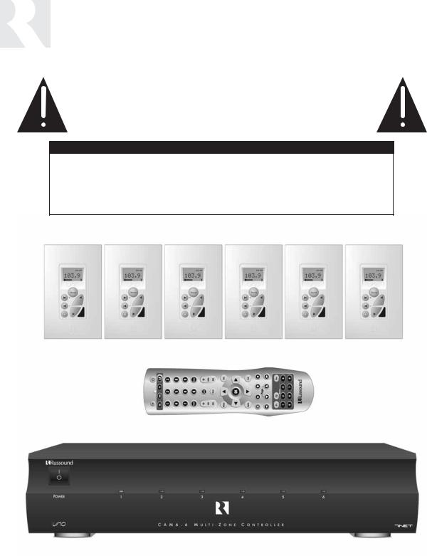
CAM6.6T-S1 System
6-Zone, 6-Source AM/FM Receiver and UNO-S1 Smart Keypads
INSTRUCTION MANUAL
IMPORTANT SAFEGUARDS
WARNING: TO REDUCE THE RISK OF FIRE OR ELECTRIC SHOCK, DO NOT EXPOSE THIS APPLIANCE TO RAIN OR MOISTURE.
CAUTION: TO REDUCE THE RISK OF ELECTRIC SHOCK, DO NOT REMOVE COVER. NO USER - SERVICEABLE PARTS INSIDE. REFER SERVICING TO QUALIFIED SERVICE PERSONNEL.
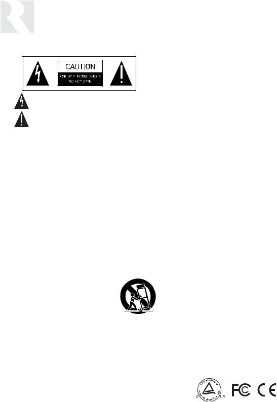
The lightning flash with arrowhead symbol, within an equilateral triangle, is intended to alert the user to the presence of uninsulated “dangerous voltage” within the product’s enclosure that may be of sufficient magnitude to constitute a risk of electric shock to persons.
The exclamation point within an equilateral triangle is intended to alert the user to the presence of important operating and maintenance (servicing) instructions in the literature accompanying the appliance.
POWER CORD NOTICE FOR INTERNATIONAL OPERATION
For 230V, 50Hz operation please select the power cord for your area. Select the plug for your area at one end and a IEC320 connector at the other. It is not necessary to make any other changes. If you have any questions please call Russound Inc. at 1-800-638-8055 or 603-659-5170
Safety Instructions:
1.Read Instructions - All the safety and operating instructions should be read before the appliance is operated.
2.Retain Instructions - The safety and operating instructions should be retained for future reference.
3.Heed Warnings - All warnings on the appliance in the operating instructions should be adhered to.
4.Follow Instructions - All operating and user instructions should be followed.
5.Water and Moisture - The appliance should not be
used near water; for example, near a bathtub, washbowl, kitchen sink, laundry tub, in a wet basement, or near a swimming pool.
6.Carts and Stands - The appliance should be used only
with a cart or stand that is recommended by the manufacturer. An appliance and cart combination should be moved with care. Quick stops, excessive force and uneven surfaces may cause the appliance and cart combination to overturn.
7.Wall or ceiling Mounting - The appliance should be mounted to a wall or ceiling only as recommended by the manufacturer.
8.Ventilation - The appliance should be situated so that its location or position does not interfere with its proper ventilation. For example, the appliance should not be situated on a bed, sofa, rug, or similar surface that may block the ventilation openings, or placed in a built-in installation, such as a bookcase or cabinet that may impede the flow of air through the ventilation openings.
9.Heat - The appliance should be situated away from heat sources such as radiators, heat registers, stoves, or other appliances (including amplifiers) that produce heat.
10.Power Sources - The appliance should be connected to a power supply only of the type described in the operating instructions or as marked on the appliance.
11.Grounding or Polarization - Precaution should be taken so that the grounding or polarization means of an appliance is not defeated.
12.Power Cord Protection - Power supply cords should be routed so that they are not likely to be walked on or pinched by items placed upon or against them, paying particular attention to cords at plugs, receptacles, and the point where they exit from the appliance.
13.Cleaning - The appliance should be cleaned only as recommended by the manufacturer.
14.Non-use Periods - The power cord of the appliance should be unplugged from the outlet when left unused for a long period of time.
15.Object and Liquid Entry - Care should be taken so that objects do not fall and liquids are not spilled into the enclosure through the openings.
16.Damage Requiring Service - The appliance should be serviced by qualified service personnel when:
A.The power supply cord or the plug has been damaged; or
B.Objects have fallen, liquid has been spilled into the appliance; or
C.The appliance has been exposed to rain; or
D.The appliance does not appear to operate normally; or
E.The appliance has been dropped or the enclosure is damaged.
17.Servicing - The user should not attempt to service the appliance beyond that described in the operating instructions. All other servicing should be referred to qualified service personnel.
Precautions:
1.Power – WARNING: BEFORE TURNING ON THE POWER FOR THE FIRST TIME, READ THE FOLLOWING SECTION CAREFULLY.
All models are designed for use with either AC120V, 60Hz or AC240, 50Hz voltages. The unit will autoswitch to either of these voltages
2.Do Not Touch The Unit With Wet Hands – Do not handle the CAM6.6 or power cord when your hands are wet or damp. If water or any other liquid enters the CAM6.6 cabinet, take the CAM6.6 to a qualified service person for inspection.
3.Location of CAM6.6 – Place the CAM6.6 in a well - ventilated location. Take special care to provide plenty of ventilation on all sides of the CAM6.6 especially when it is placed in an audio rack. If ventilation is blocked, the CAM6.6 may overheat and malfunction. Do not expose the CAM6.6 to direct sun light or heating units as the CAM6.6 internal components temperature may rise and shorten the life of the components. Avoid damp and dusty places.
4.Care – From time to time you should wipe off the front and side panels of the cabinet with a soft cloth. Do not use rough material, thinners, alcohol or other chemical solvents or cloths since this may damage the finish or remove the panel lettering.
2

TABLE OF CONTENTS
USER SECTION |
|
Product Introduction ............................................................................................................ |
6 |
Component Guide |
|
CAM6.6 Controller............................................................................................................... |
7 |
UNO-S1 Keypad .................................................................................................................. |
8 |
UNO-S2 Keypad (Optional).................................................................................................... |
9 |
SRC2 Remote Control........................................................................................................ |
10 |
Operation |
|
UNO-S1 Keypad Operation ................................................................................................. |
11 |
UNO-S1 User Menu ........................................................................................................... |
12 |
Optional UNO-S2 Keypad Operation .................................................................................... |
13 |
Optional UNO-S2 User Menu .............................................................................................. |
14 |
Internal Source - AM/FM Tuner |
|
UNO-S1 Keypad Control..................................................................................................... |
15 |
UNO-S2 Keypad Control ............................................................................................... |
16-17 |
SRC2 Remote Control .................................................................................................. |
18-19 |
INSTALLER SECTION |
|
Getting Started |
|
Unpacking ........................................................................................................................ |
22 |
System Components ......................................................................................................... |
22 |
Tools Needed.................................................................................................................... |
22 |
System Installation Considerations...................................................................................... |
22 |
Connection Tips ................................................................................................................ |
22 |
Wiring Instructions |
|
Keypad Wiring................................................................................................................... |
23 |
Speaker Wiring ................................................................................................................. |
23 |
Component Guide |
|
CAM6.6 Controller Rear Panel ....................................................................................... |
24-25 |
UNO-S1 Keypad Front Panel............................................................................................... |
26 |
UNO-S1 Keypad Rear Panel ............................................................................................... |
27 |
Keypad Installation |
|
UNO-S1 Keypad Location .................................................................................................. |
28 |
UNO-S2 Keypad Installation................................................................................................ |
29 |
Making Connections |
|
UNO-S1 Keypad Port Connections ...................................................................................... |
29 |
Source Audio Input Connections ......................................................................................... |
30 |
3

TABLE OF CONTENTS
Source IR Input Connections .............................................................................................. |
30 |
Common IR Input Connection ............................................................................................. |
31 |
Speaker Connections ........................................................................................................ |
32 |
Zone Fixed/Variable Audio Output ....................................................................................... |
33 |
12VDC Home Theater Trigger In/Out .................................................................................. |
34 |
12VDC Mute Trigger In/Out................................................................................................ |
35 |
RNET Link In/Out............................................................................................................... |
36 |
RS-232 Interface ............................................................................................................... |
37 |
Optional Internal Source |
|
AM/FM Tuner Antennas............................................................................................... |
38-40 |
Initial Install Test................................................................................................................ |
41 |
Programming |
|
System Programming Overview ..................................................................................... |
42-43 |
Setup Forms |
|
Source Information Form................................................................................................. |
44 |
Zone Information Form .................................................................................................... |
45 |
Macro Editor Form.......................................................................................................... |
46 |
Installation Menu |
|
Installation Menu Overview ............................................................................................. |
47 |
Peripheral Setup ....................................................................................................... |
48-50 |
Source Setup ........................................................................................................... |
50-56 |
Basic Setup............................................................................................................ |
50-52 |
Zone Setup .............................................................................................................. |
56-57 |
Controller Setup ....................................................................................................... |
57-58 |
Power Management .................................................................................................. |
58-60 |
Learn IR........................................................................................................................ |
60 |
Macro Editor ............................................................................................................ |
60-61 |
System Info................................................................................................................... |
62 |
Setup Menu Flow Charts ........................................................................................... |
63-75 |
REFERENCE SECTION |
|
IR Device Code List .......................................................................................................... |
76-78 |
IR Keycode List .............................................................................................................. |
79-100 |
Source Names ............................................................................................................. |
101-102 |
Sample Configurations.................................................................................................. |
103-106 |
Technical Specifications....................................................................................................... |
107 |
Warranty ............................................................................................................................ |
108 |
All trademarks are the property of their respective owners. |
|
4
USER SECTION
Component Guides
Explains front panel features of the CAM6.6 controller,
UNO-S1 keypad, optional UNO-S2 keypad and SRC2 remote control.
Operation
Step-by-step outline of the system's normal operation,
plus a look at adjustable features available through the User Menu.
5

PRODUCT INTRODUCTION
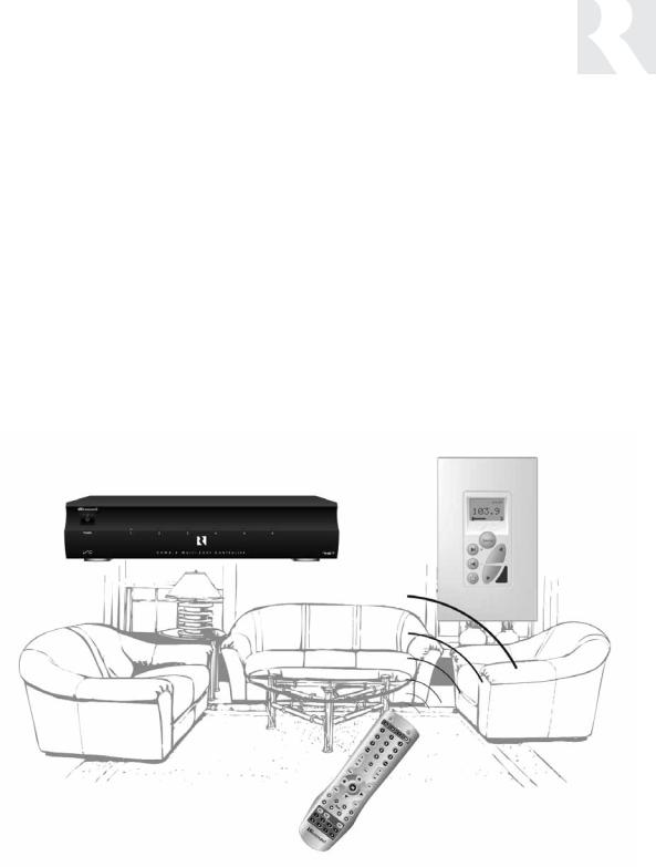
Thank you for choosing the Russound® CAM6.6T-S1 System to enhance your home with distributed audio. This system’s state-of-the-art features and components blend seamlessly with your unique lifestyle and preferences.
Besides distributing and controlling six audio sources to six rooms (zones), your CAM6.6T-S1 System offers many features that increase your enjoyment of living. Here are several that you may find particularly beneficial.
Internal Source
The CAM6.6T includes an optional internal source - an AM/FM tuner module. The tuner can store up to 36 favorites, or memory presets. These are stored in groups of six called banks, and there are six banks. Each preset and each bank can be given a custom name of your choice.
Favorites
The SRC2 remote and the optional UNO-S2 keypad’s F1 and F2 buttons are preset favorites. These easy-to-set buttons make it possible to hear your favorite radio station or watch your favorite satellite channel at just the right volume in your room with just a button push. Want something new? Just resave the Favorite with a new choice.
Do Not Disturb
The Do Not Disturb mode prevents unwanted interruptions in your room and stops changes to your selected audio source. You may have a nursery or study that you want to keep quiet, or maybe you are watching a DVD and don’t want it interrupted. Simply set the Do Not Disturb mode to “on” using the User Menu, and be free from Party Mode interaction and system-wide functions like “All On” or “All Off.”
Party Mode
Ready to set the mood? In Party Mode, you just pick the source and the sound settings and hear the music throughout all the rooms. The Master keypad simultaneously controls all the keypads in all the rooms to effortlessly select or control the components. A great benefit of the Party Mode feature is the ability to transfer the Master keypad mode to any keypad in the system. If the living room is the center of the party, use that room’s keypad as Master. If the party moves to the sunroom and porch, that room’s keypad can be set to Master instead.
Here at Russound we are proud to continue providing innovative and intuitive audio product solutions to the world. When you link the industry-leading CAM6.6T-S1system with Russound’s commitment to its products and customers, you have truly made – “the right connection.”
6
USER
COMPONENT GUIDE
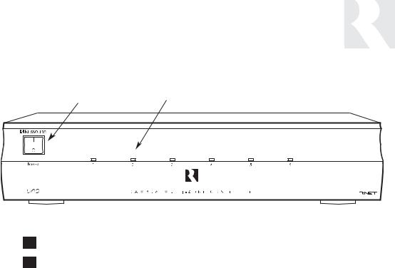
CAM6.6 Controller-Front Panel
1 |
|
2 |
1MAIN POWER SWITCH - Supplies power to the CAM6.6
2ROOM LED ON/OFF INDICATORS - Indicates when a room is on (green) or off (red)
Main Power and Zone Status
The power switch for the CAM6.6 controller is “on” in the up position. Any active room (1-6) is indicated on the front of the controller by a green LED, which shows red when the room is inactive. In most basic installations, all functions and room settings are controlled through the corresponding UNO systems keypads.
7
USER
COMPONENT GUIDE
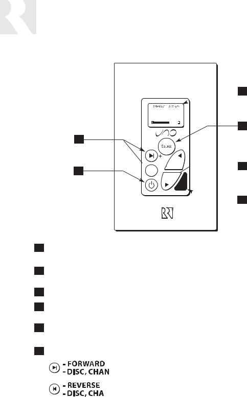
UNO-S1 Keypad
 1
1
102.5
2
6

 3 5
3 5 


 4
4
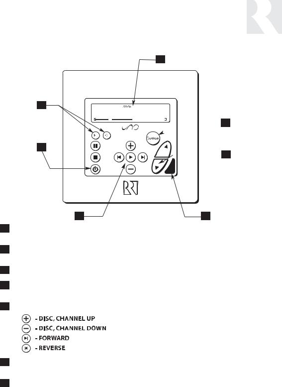
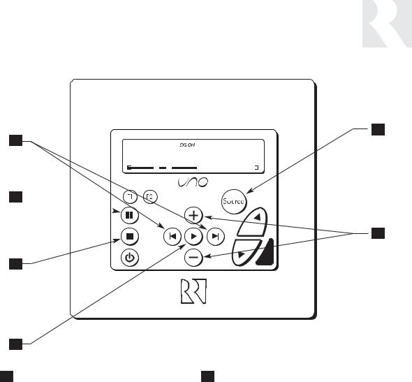
1LCD PANEL - 5-character backlit display shows status of the room, source, volume, and more
2SOURCE SELECT BUTTON - Scrolls through the sources directly connected to the CAM6.6. Press and hold brings up the USER MENU for loudness, bass, treble, etc.
3VOLUME UP/DOWN BUTTONS - Raises and lowers the volume for the room
4IR RECEIVER - Receives IR signals and passes them to the controller and source equipment. Also used when operating the UNO Keypad by using the SRC2 remote
5POWER BUTTON - Turns room ON or OFF when pressed once, press and hold a second time will turn on or off all CAM6.6 rooms
6COMMAND KEYS - Pressing the command keys controls the source equipment
(press)


 (press and hold)
(press)


 (press and hold)
8
USER
COMPONENT GUIDE
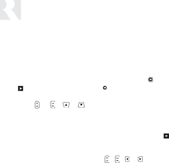
Optional UNO-S2 Keypad
1
7
CD PLAYER 1
 2
2
6
 3
3
5 |
4 |
1LCD PANEL - 12-character backlit display shows status of the room, source, volume, and more
2SOURCE SELECT BUTTON - Scrolls through the sources directly connected to the CAM6.6. Press and hold brings up the USER MENU for loudness, bass, treble, etc.
3VOLUME UP/DOWN BUTTONS - Raises and lowers the volume for the room
4IR RECEIVER - Receives IR signals and passes them to the controller and source equipment. Also used when operating the UNO Keypad by using the SRC2 remote
5COMMAND KEYS - Pressing the command keys controls the source equipment
6POWER BUTTON - Turns room ON or OFF when pressed once, press and hold a second time will turn on or off all CAM6.6 rooms
7F1 AND F2 BUTTONS - Selects Favorite 1 or Favorite 2 - preset user-selected favorite settings per room
9
USER
COMPONENT GUIDE
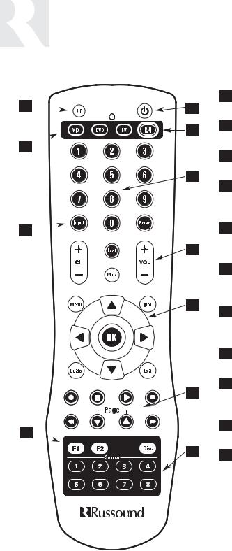
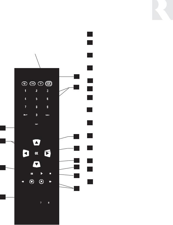
SRC2 Remote Control
11 
10 
9 
8 
1
2
3
4
5
6
7
1POWER - Turns room or Local Source on and off.
2RUSSOUND DEVICE BUTTON - Selects Russound Keypad for control by SRC2.
3NUMBER BUTTONS - Buttons (0-9) for direct selection of channels or discs.
4VOLUME UP/DOWN - Raises and lowers the volume for the room you are in, or for the selected Local Device.
5CURSOR KEYS - Issues IR commands for source equipment, allowing movement through menus and program screens.
6COMMAND KEYS - Controls the selected device (e.g., VCR, DVD, or CD player) with these buttons.
7SOURCE - Directly select sources connected to the Russound controller while in the Russound mode.
8F1 AND F2 BUTTONS - Selects and saves Favorite 1 or Favorite 2 preset selections.
9INPUT - Scrolls through sources while in the Russound mode, or switches inputs on selected Local Source.
10LOCAL DEVICE BUTTONS - Selects Local Source to be controlled by SRC2.
11SETUP - Use for programming SRC2 using the built-in library or by learning-in codes.
10
Zone On/Off
Press and release  to turn on the UNO System Keypad. This also turns on the corresponding CAM6.6’s room, and any presets previously assigned will be activated, including settings for bass, volume, last source selected, etc. Press and release
  to turn off the UNO System Keypad. This will also put the corresponding CAM6.6’s room into a standby state.
System All On/Off
An “All On” command is issued by pressing  and holding for 3 seconds, after an initial room has been turned on. An “All Off” command can be issued to all rooms by pressing and holding
 after the room has been turned off.
System On Indicator
When the room is off, but the system is on in another room,  is illuminated by a green backlight and the "SYS ON" icon remains visible.
Source Select Button
 scrolls through the six audio source inputs. To change sources, press and release
  . As the sources are sequentially selected, each source's name appears on the keypad LCD panel. When a source is selected in more than one room, the “SHARED” icon will appear on all UNO Keypads using that source.
  is also
USER
OPERATION
UNO-S1 Keypad
used to enter the User Menu with a press and hold action. (See next page for User Menu)
Volume Up/Down Buttons
The room’s audio output is adjusted using  .
.
Command Keys
The command keys 
 allow control of the selected source at the UNO Keypad. The command keys are activated with a press and release, or press and hold to access secondary functions.
11

USER
USER MENU SETTINGS
UNO-S1 User Menu Operation
The User Menu allows the user to adjust the audio properties and control functions of a particular room.
To enter or exit the User Menu, press and hold


 during normal operation. The following keys are used to navigate and make changes while using the User Menu:
 Press and hold to adjust feature setting (increment)
 Press and hold to adjust feature setting (decrement)
 Go to next feature.
 Go to previous feature.
  View current feature setting.
UNO-S1 User Menu
Note: When within the UNO-S1 User Menu, if no keys are pressed, the display will revert back to its runtime display.
The following features make up the User Menu:
Bass  Treb
Treb  Loud
Loud  Bal
Bal  OnVol
OnVol 
Bkgnd  DND
DND  Party
Party 
Feature and Setting:
1.Bass -10 < Bass:Flat > +10
2.Treb (Treble) -10 < Treble:Flat > +10
3.Loud (Loudness) (more bass, fuller sound) On or Off
4.Bal (Balance) Left 10 < Center > Right 10
5.OnVol (Turn on Volume) (default room volume level) 0 to 100 (in steps of 2)
6.Bkgnd (Background Color) (keypad background light) Amber or Green or Off
7.DND (Do Not Disturb) - On or Off (default)
Do Not Disturb means do not disturb this room or selected source. This stops pages from being sent to this room, stops an “All Off," "All On" or
Party Mode command from affecting this room. When another UNO Systems Keypad selects the same source, a DND message will scroll on the the LCD panel, alerting the user the source is in Do Not Disturb mode.
8. Party (Party Mode) - Master or Off
When in “PARTY MODE” the system is primarily controlled by a “MASTER” Keypad. Party Mode links all rooms to the same source which is selected by the Master Keypad room. Any keypad in the system can become a Master Keypad (if enabled) but only one Master Keypad may exist at a time in Party Mode. Selecting Master Keypad mode from another keypad will transfer Master Keypad control to that room and release it from the first. When the source selected in the Master Keypad room is changed then the source for all rooms changes as well. The keypad will scroll a PARTY message on the LCD panel. It will scroll a MASTR message in lieu of PARTY if Master is enabled.
Volume level changes at the Master Keypad will be reflected in all rooms in Party Mode. NonMaster zones in Party Mode can temporarily override Master Keypad volume level adjustments for their particular room preference. Master Keypad will not change Bass, Treble, or Loudness adjustments for any other rooms other than the Master Keypad room. Every other keypad will still operate its respective bass, treble, balance and loudness adjustments for that room.
12
Zone On/Off
Press and release  to turn on the UNO System Keypad. This also turns on the corresponding CAM6.6’s room, and any presets previously assigned will be activated, including settings for bass, volume, last source selected, etc. Press and release
  to turn off the UNO System Keypad. This will also put the corresponding CAM6.6’s room into a standby state.
System All On/Off
An “All On” command is issued by pressing  and holding for 3 seconds, after an initial room has been turned on. An “All Off” command can be issued to all rooms by pressing and holding
 after the room has been turned off.
System On Indicator
When the room is off, but the system is on in another room,  is illuminated by a green backlight and the "SYS ON" icon remains visible.
Source Select Button
 scrolls through the six audio source inputs. To change sources, press and release
  . As the sources are sequentially selected, each source's name appears on the keypad LCD panel. When a source is selected in more than one room, the “SHARED” icon will appear on all UNO Keypads using that source.
  is also
USER
OPERATION
Optional UNO-S2 Keypad
used to enter the User Menu with a press and hold action. (See next page for User Menu)
Volume Up/Down Buttons
The room’s audio output is adjusted using  .
.
F1 and F2 Buttons
The |
and |
buttons are user favorite pre- |
sets. These presets can be selected at any time to recall source selection, volume, and favorite channel, disk, etc. To store a favorite preset: first, adjust the room settings and select a source to be
stored. Next, press and hold the desired |
or |
 button until SAVED is displayed on the LCD
panel. Now a press and release of the button will recall the favorite preset. To set a favorite num-
bered disk or channel, use |
or |
to select a |
disk or channel (e.g., channel 45). Wait for the keypad to show the source name, then press and hold the F1 or F2 within 15 seconds of setting the numeric selection to save the setting.
Command Keys
The command keys allow control of the selected source at the UNO Keypad. The command keys are activated with a press and release, or press and hold to access secondary functions.
13

USER
USER MENU SETTINGS
Optional UNO-S2 User Menu Operation
The User Menu allows the user to adjust the audio properties and control functions of a particular room.
The following keys are used to navigate and make changes while using the User Menu:
To enter the User Menu, press and hold 
during normal operation. To exit the User Menu, press and release  .
.
 Adjust feature setting (increment).
 Adjust feature setting (decrement).
 Go to next feature.
 Go to previous feature.
 View current feature setting.
Note: When within the UNO-S2 User Menu, if no keys are pressed, the display will revert back to its runtime display.
The following features make up the User Menu:
BASS  TREBLE
  LOUDNESS
  BALANCE
 TURN ON VOL
  BG COLOR
  DO NOT DSTRB
  PARTY MODE
Feature and Setting:
1. BASS
-10 < Bass:Flat > +10
2. TREBLE
-10 < Treble:Flat > +10
3.LOUDNESS (more bass, fuller sound) On or Off
4.BALANCE
Left -10 < Center > Right +10
5.TURN ON VOL (default room volume level) 0 to 100
6.BG COLOR (keypad background light) Amber or Green or Off
7. DO NOT DSTRB - On or Off (default)
Do Not Disturb means do not disturb this room or selected source. This stops pages from being sent to this room, stops an “All Off," "All On" or Party Mode command from affecting this room.
When another UNO Systems Keypad selects the same source, a DND icon will appear alerting the user the source is in Do Not Disturb mode.
8. PARTY MODE - Master (Enable) or Off (Disable)
When in “PARTY MODE” the system is primarily controlled by a “MASTER” keypad. Party Mode links all rooms to the same source which is selected by the Master Keypad room. Any keypad in the system can become a Master keypad (if enabled) but only one Master Keypad may exist at a time in Party Mode. Selecting Master keypad mode from another keypad will transfer Master keypad control to that room and release it from the first. When the source selected in the Master keypad room is changed then the source for all rooms changes as well.
Volume level changes at the Master Keypad will be reflected in all rooms in Party Mode. NonMaster zones in Party Mode can temporarily override Master Keypad volume level adjustments for their particular room preference. F1 and F2 favorite presets selected from the Master Keypad will be enabled in all rooms in Party Mode. Master Keypad will not change Bass, Treble, or Loudness adjustments for any other rooms other than the Master Keypad room. Every other keypad will still operate its respective bass, treble, balance and loudness adjustments for that room.
14
UNO-S1 Keypad Control of Tuner
Selecting the tuner
On the UNO-S1 keypad, press  to select the AM/FM tuner by choosing the tuner’s preassigned source number (1).
102.5
2
USER
INTERNAL SOURCE - AM/FM TUNER
UNO-S1 Keypad Control
Selecting the desired frequency
Press and hold  or
or  to activate manual tuning. Once active, press
  or
or  to scroll
through frequencies. The frequency will scroll
twice on the keypad then stop and display the
station’s first 5 characters.
1
1 |
TUNER SELECTION - Select |
|
source number assigned to |
|
AM/FM Tuner (1) |
2 |
FREQUENCY SELECTION - |
Scrolls through frequencies (press and hold, then press)
15

USER
INTERNAL SOURCE - AM/FM TUNER
UNO-S2 Keypad Control
UNO-S2 Keypad Control of Tuner
Selecting the tuner
On the UNO-S2 keypad, press  to select the AM/FM tuner by choosing the tuner’s preassigned source number (1).
Selecting the desired band
Push  to toggle between AM band and FM band reception.
of six called banks, and there are six banks. Each preset and each bank can be given a custom name of your choice.
To select a bank, press and hold  for bank up or
  for bank down. The bank’s name will be temporarily displayed on the UNO-S2. Banks and memory presets are custom-named in the Peripheral Setup Menu (see Installation Menu section of this manual).
Selecting the desired frequency
Use  and
and  for manual tuning. The frequency will appear on the keypad and the active tuner. To move quickly through the stations, press and hold either
  or
or  for more than 1.5 seconds.
Frequency Seek
A press on  will seek the next higher tuneable station. If a tuneable station is not found, end the SEEK function by pressing
  again.
Frequency Scan
To scan, press and hold then release  . The tuner scans through tuned stations with a 5-sec- ond preview before moving to the next station. To end scanning, press
  again.
Selecting a Bank
The AM/FM tuner can store up to 36 favorites, or memory presets. These are stored in groups
Recalling a Memory Preset
Press  and
and  to scroll through the memory presets for the selected bank. This procedure will step through all of the presets in the current bank, then loop back to start at the first one.
Only configured presets will be displayed.
Mute
Press  to mute/unmute the tuner audio output.
16
USER
INTERNAL SOURCE - AM/FM TUNER
UNO-S2 Keypad Control
1
6
92.5 MHz FM
5
2
4
3
1TUNER SELECTION - Select source number assigned to AM/FM TUNER (1)
4SCAN - (press and hold) Scans through tuned stations with 5-second preview before next station
|
|
|
5 |
|
MUTE - Mutes/unmutes tuner audio output |
|
2 |
TUNE UP/DOWN - Used for manual station |
|||||
|
|
|||||
|
selection |
|
|
BANK SELECT - (press and hold) Used for bank |
||
|
6 |
|||||
|
|
|
||||
|
|
|
|
|
selection |
|
3 |
SELECT - Selects AM or FM band |
|||||
|
||||||
|
|
|
|
|||
|
|
6 |
|
MEM UP/DOWN - (press) Scrolls through memory |
||
4 |
SEEK - (press) Seeks next higher tuned station |
|||||
|
|
preset stations |
||||
|
|
|
|
|
||
17
USER
INTERNAL SOURCE - AM/FM TUNER
SRC2 Remote Control
SRC2 Control of Tuner
Selecting the tuner
To select the tuner, push  and choose the source number preassigned to the AM/FM tuner (1), or use the UNO numeric source inputs at the bottom of the SRC2.
Selecting the desired band
Push |
to toggle between AM/FM reception. |
|||
Selecting the desired frequency |
|
|||
Use the Channel |
and |
or |
and |
|
for manual tuning. To move quickly through the channels, press and hold the button for more than 1.5 seconds. To directly select a station, enter the threeor four-digit channel or frequency (1071 for 107.1, etc.). European regions use five-digit station frequencies.
Frequency Seek
The SEEK function is performed by pressing and releasing the Select  or
or  or
or  . To seek higher frequency station press
  . Press
  for lower frequencies. Tuning begins at the current frequency, seeks upward (or downward) and stops at the next tuned station. Pushing
  or
or  again continues the SEEK function. Once the highest frequency is reached, the tuner continues SEEK mode at the lowest frequency.
Frequency Scan
To scan, press and hold then release  . The tuner scans through tuned stations with a 5-second preview before moving to the next station. To end scanning, press
  again.
Selecting a Bank
To select a bank, press and hold |
for bank up |
||
or |
|
for bank down. |
|
|
|
||
|
|
|
|
Bank/Memory Presets
The AM/FM tuner has six banks of preset memory settings, and each bank holds six presets for a total of 36 possible presets.
Memory Preset Programming
1. Select a bank - press and hold  or
or
until the desired bank # (1-6) appears on the keypad. 2. Select a station - tune to the desired frequency
with |
, |
, |
or |
. |
|
3. Press and hold a # button (1-6) until M(#) SA(ved) is displayed.
Recalling a Memory Preset
Press  and
and  to scroll through a loop dis-
play of all the configured memory presets for the currently selected bank.
Mute
Press the  button to mute/unmute the tuner audio output.
18
RUSSOUND SELECTION - “R” must be the selected source for control of the CAM6.6 and any connected components. Select “R” before sending SRC2 remote commands.
1
2
11
3
10
4
|
3 |
9 |
5 |
|
6 |
7
8
USER
INTERNAL SOURCE - AM/FM TUNER
SRC2 Remote Control
1POWER - Power managed by CAM6.6
2NUMERIC INPUT - (press) Number buttons for direct input of frequency
2MEMORY PRESETS - (press and hold) Number buttons (1-6) for saving memory presets
3TUNE UP/DOWN - Incrementally scrolls through channels or tuned stations
4OK - Confirms numeric selection
5PLAY - Selects AM or FM band
6SCAN - (press and hold) Scans through tuned stations with 5-second preview before next station
6SEEK UP/DOWN - (press) Seeks next tuned station up or down
7MEM UP/DOWN - (press) Scrolls through memory presets for selected bank
7BANK UP/DOWN - (press and hold) Used for bank selection
8TUNER SELECTION - Select AM/FM Tuner by its assigned source number
9PAUSE - Mutes/unmutes tuner audio output
10SEEK UP/DOWN - Seeks next tuned station up or down
11TUNE UP/DOWN - Incrementally scrolls through tuned stations
19
CAUTION
Do not connect the controller's main power feed until all other connections have been made and verified. Live connection or removal of the keypad wiring or other wiring when the system is powered can cause communication problems in the network. Double-check terminations during each phase of the installation to prevent accidental damage. Incorrect wiring is the number one cause for non-warranty product damage.
20
INSTALLER SECTION
Getting Started
Includes an installation overview, including tools needed and wiring instructions.
Component Guides
Reviews front and back panel features of the CAM6.6 controller and the UNO-S1 keypad.
Keypad Installation
Explains UNO-S1 keypad installation and wiring.
Making Connections
Details front and back panel connections of the controller and the keypad.
System Programming Overview
Outlines the programming planning process, and includes information forms to complete prior to programming.
Installation Menu
Explains the programming menus that set up controller, keypad, source and zone operations.
Setup Menu Flow Charts
Presents the programming menus in a graphical flow chart format.
IR Device Codes
A list of controller’s IR device code library for source Device Code entries.
Key Function Codes
A list of IR codes for each command type contained in the built-in library.
Source Names
A list of Source Names available for assignment.
Sample Configurations
Diagrams of various configurations using CAM6.6s and other components.
21

INSTALLER
GETTING STARTED
Unpacking the System Components
•Keep the original carton and packing materials for future shipment or storage.
•Check for any visible signs of damage. If you encounter any concealed damage, consult your Russound dealer before proceeding to install the unit.
•Retain the sales receipt as it establishes the duration of the limited warranty and provides information for insurance purposes.
CAM6.6T-S1 System Components:
•1 (one) CAM6.6 Controller/Amplifier
•6 (six) UNO-S1 System Control Keypads
•1 (one) SRC2 Learning/Preprogrammed Remote Control
•6 (six) 845.1 Micro Emitters
Tools needed for installation:
•Drill with a 1/2” x 6” drill bit
•Keyhole saw
•Flat head screwdriver (medium size)
•Phillips Screwdriver (cordless recommended)
•110 punchdown tool (included)
•Modular RJ-45 crimper and connectors
•Pair of diagonal cutters or wire strippers
•Stud finder
•Steel wire fish tape
•Cable staples
•Single-gang electrical work boxes
System Installation Considerations
There are several factors to consider before installing the Russound CAM6.6T-S1 system:
•What are the intended listening zones?
•What system options and accessories might be required for features such as local sources, etc.?
•From where in each zone will the user prefer to control the system? Where will the keypads be located? Where will the speakers be located?
•Where will the source equipment be located? The CAM6.6 must have proper ventilation above and below for air circulation and heat dissipation. A rack-mount location may require fans and vents.
Connection Tips
•It is recommended that the CAM6.6 and the source equipment be plugged into a dedicated 20-amp circuit with an isolated ground. A power line conditioner can reduce interference problems caused by noise found in some electrical systems.
•Disconnect all live power cords before making connections to the controller.
•Verify that all connections and polarity are correct.
•Keep all power cords away from all signal cables to prevent humming from induced noise.
•Choose reliable signal cables/patch cords.
•Label all wires with room location at both ends of the wire.
22
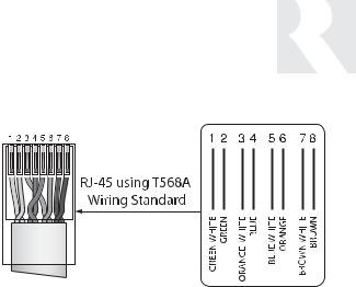
RJ-45 Connections
The CAT-5 T568A wiring standard shown on the right is used for the RJ-45 terminations.
Keypad Wiring
For the UNO-S1 keypad, the following connections are used to terminate the CAT-5 wire to the 110 punchdown on the keypad:
CAT-5 WIRE COLOR |
TYPE |
Brown . . . . . . . . . . . . . . . . . . . +12V
Brown/White . . . . . . . . . . . . . . +12V
Green . . . . . . . . . . . . . . . . . . Ground
Green/White . . . . . . . . . . . . Status In
Orange . . . . . . . . . . . . . . . . . Ground
Orange/White . . . . . . . . . . . . . IR Out
Blue . . . . . . . . . . . . . . . . . . . COM A
Blue/White . . . . . . . . . . . . . . COM B
•To determine the amount of CAT-5 wire required for the system installation, first decide how many keypads will be used, then determine the distance between each intended keypad location to the intended CAM6.6 location. The maximum recommended wire run length is 250 feet for each UNO-S1 keypad.
•Make sure that the entire wire path between keypads and CAM6.6 is clear and not obstructed by a floor ceiling joist, or masonry wall which can’t be drilled through.
INSTALLER
WIRING INSTRUCTIONS
•Confirm ahead of time that you can drill an outlet hole easily and in an unobtrusive spot to connect wires with the CAM6.6.
•Label wires with keypad and room location. This simplifies CAM6.6 hook-up once the keypads and speakers are installed.
Speaker Wiring
Standard 16-gauge 4-conductor stranded speaker wire can be run up to to 125 feet; 14-gauge wire can be run up to 250 feet.
When running wire, pay particular attention to the following areas:
•Avoid locations concealing pipes, heating ducts and AC wiring in the general vicinity.
•Avoid running wires close to house electrical wiring for any distance. If you have to run them parallel, make sure to space the wires at least two feet from the AC line.
23
INSTALLER
COMPONENT GUIDE
CAM6.6 Controller-Rear Panel
|
1 |
|
|
|
|
|
|
2 |
|
3 |
|
4 |
|
|
|
5 |
|
|
|
6 |
|
7 |
|
8 |
|
|
9 |
|
10 |
|
|
11 |
|
||||||||||||||||||||||||||||||||||||||||||||||||||||
|
|
|
|
|
|
|
|
|
|
|
|
|
|
|
|
|
|
|
|
|
|
|
|
|
|
|
|
|
|
|
|
|
|
|
|
|
|
|
|
|
|
|
|
|
|
|
|
|
|
|
|
|
|
|
|
|
|
|
|
|
|
|
|
|
|
|
|
|
|
|
|
|
|
|
|
|
|
|
|
|
|
|
|
|
|
|
|
|
|
|
|
|
|
|
|
|
|
|
|
|
|
|
|
|
|
|
|
|
|
|
|
|
|
|
|
|
|
|
|
|
|
|
|
|
|
|
|
|
|
|
|
|
|
|
|
|
|
|
|
|
|
|
|
|
|
|
|
|
|
|
|
|
|
|
|
|
|
|
|
|
|
|
|
|
|
|
|
|
|
|
|
|
|
|
|
|
|
|
|
|
|
|
|
|
|
|
|
|
|
|
|
|
|
|
|
|
|
|
|
|
|
|
|
|
|
|
|
|
|
|
|
|
|
|
|
|
|
|
|
|
|
|
|
|
|
|
|
|
|
|
|
|
|
|
|
|
|
|
|
|
|
|
|
|
|
|
|
|
|
|
|
|
|
|
|
|
|
|
|
|
|
|
|
|
|
|
|
|
|
|
|
|
|
|
|
|
|
|
|
|
|
|
|
|
|
|
|
|
|
|
|
|
|
|
|
|
|
|
|
|
|
|
|
|
|
|
|
|
|
|
|
|
|
|
|
|
|
|
|
|
|
|
|
|
|
|
|
|
|
|
|
|
|
|
|
|
|
|
|
|
|
|
|


 CAM6.6
|
|
|
|
|
|
|
|
|
|
|
|
|
|
|
|
|
|
|
|
|
|
|
|
|
|
|
|
|
|
|
|
|
|
|
|
|
|
|
|
|
|
|
|
|
|
|
|
|
|
|
|
|
|
|
|
|
|
|
|
|
|
|
|
|
|
|
|
|
|
|
|
|
|
|
|
|
|
|
|
|
|
|
|
|
|
|
|
|
|
|
|
|
|
|
|
|
|
|
|
|
|
|
|
|
|
|
|
|
|
|
|
|
|
|
|
|
|
|
|
|
|
|
|
|
|
|
|
|
|
|
|
|
|
|
|
|
|
|
|
|
|
|
|
|
|
|
|
|
|
|
|
|
|
|
|
|
|
|
|
|
|
|
|
|
|
|
|
|
|
|
|
|
|
|
|
|
|
|
|
|
|
|
|
|
|
|
|
|
|
|
|
|
|
|
|
|
|
|
|
|
|
|
|
|
|
|
|
|
|
|
|
|
|
|
|
|
|
|
|
|
|
|
|
|
|
|
|
|
|
|
|
|
|
|
|
|
|
|
|
|
|
|
|
|
|
|
|
|
|
|
|
20 |
|
19 |
|
18 |
|
17 |
|
|
|
|
|
|
|
16 |
|
15 |
|
|
|
|
|
|
|
|
|
|
|
|
|
14 |
|
|
|
|
|
|
|
|
|
|
|
|
|
|
|
|
13 |
|
|
|
|
12 |
||||||||||
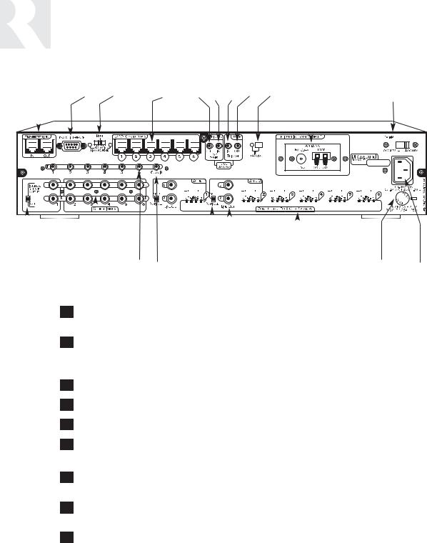
1RNET LINK IN AND LINK OUT - Links multiple CAM6.6’s, also links future Russound components that are RNET compatible
2RS-232 INTERFACE - The RS-232 Interface allows the zones to be controlled by PC or other devices that have an RS-232 Interface. The RS-232 Interface also allows for firmware updates and programming.
3AUX-MAIN RUN SWITCH - For firmware updates
4UNO KEYPAD PORTS - One UNO Keypad Port for each of the six CAM6.6 Zones
512VDC TRIGGER OUT - 12VDC 100ma Trigger Out turns on when any zone is on
6HOME THEATER 12VDC TRIGGER IN - 12VDC input jack notifies the CAM6.6 that additional components are active, e.g., home theater equipment
7MUTE 12VDC TRIGGER IN - Applying 12VDC to the Mute 12VDC Trigger In jack will mute audio for assigned CAM6.6 Zones
8MUTE 12VDC TRIGGER OUT - Mute Trigger Out supplies 12VDC 100 mA whenever 12VDC is applied to the Mute 12VDC Trigger In
9IR LEARNING WINDOW - IR receiver for learning in IR commands with confirmation LED
24

INSTALLER
COMPONENT GUIDE
CAM6.6 Controller-Rear Panel
10OPTIONAL INTERNAL SOURCE - Factory installed optional internal source, AM/FM radio module
11AC 240V-AC 110V Switch - Switches A/C input voltage between 110VAC and 240VAC
12AC 120/240 INPUT - Grounded 3-terminal plug detachable power cord connection for the CAM6.6
13FUSE HOLDER - Holds a replaceable fuse for A/C input connection 110VAC operation - F 3A H 250V, 240VAC operation; T 1.25A H 250V
14SPEAKER OUTPUTS - Connect 8 Ohm speakers for each zone with detachable colorcoded modular snap connectors
15AUDIO OUTPUTS - Audio line output connection
16FIXED/VARIABLE SWITCH - Change line out between fixed and variable output.
17COMMON IR OUTPUT - Output jack will pass all IR signals from all keypads
18SOURCE IR OUTPUTS - Six source-specific IR Output jacks allow for IR control of source equipment
19AUDIO INPUTS - Six sets of Audio Line Level input connections for CAM6.6 source components
20OUTPUT/INPUT SWITCH - Enable Source Input 1 or enables Internal Source 1 output
25
INSTALLER
COMPONENT GUIDE
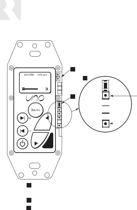
UNO-S1 Keypad-Update Port
Src 3
1
|
3 |
2 |
Data Rx TTL Level |


 Data Tx TTL Level


 GND
GND 

 +12VDC
Note: Do not put RS-232-level signals into the pins. Must use Advanced Programming Cable P/N 2500-521065.
1OS Update/Run Jumper -The pins are jumpered when performing an OS update on the keypad, and removed during normal operation.
(Typically needed only on a keypad that has never been updated)
2Setup Button - Activates information and update menus for the keypad.
3OS Update Port - Used to update the UNO-S1 keypad operating system firmware. If an update is released, it will be available online through the Document Center on www.russound.com. Look for it in the “Firmware and Downloads” section under Multi-Zone product type. The Advanced Programming Cable is available from Russound, Part #2500521065.
26
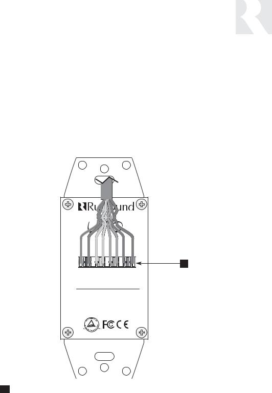
CAT-5 Connection
The UNO-S1 Keypad uses a 110-punchdown terminal to provide a simple installation and strong connection for CAT-5 cable’s eight conductors. Punchdown terminals require the use of a punchdown tool which has been provided with the keypad kit. Attach the CAT-5 cable to the 110-punchdown terminal on the UNO-S1 Keypad as shown, matching the conductor colors to the connection color guide. The keypad will not operate properly if the terminations deviate from the required connection order.
INSTALLER
COMPONENT GUIDE
UNO-S1 Keypad-CAT-5 Connection
Caution:
Take care when using an impact 110 punchdown tool, as this may overspread the contact points. Use of the impact tool may propel stray bits of wire and jacket into the keypad’s chassis and possibly cause a short in the circuitry. Gently shake or blow air through the keypad chassis to remove stray wire before the keypad is installed into the junction box.
|
NEWMARKET, NH U.S.A. |
|||||||
|
|
|
UNO-S1 |
|
|
|
||
INMADEKOREA |
System Control Keypad |
|||||||
BL/W |
BL |
OR/W |
OR |
GR/W |
GR |
BR/W |
BR |
|
|
|
|
|
|
|
|
|
1 |
DESIGNED IN USA |
COM B |
COM A |
IR OUT |
GND |
STATUS IN |
GND |
+12V |
+12V |
1110 PUNCHDOWN CONNECTOR - Termination for CAT-5 connection between the UNO-S1 Keypad and the CAM6.6 controller.
27
INSTALLER
UNO-S1 KEYPAD-INSTALLATION
Keypad Location
The best infrared remote performance is achieved with the keypad away from any direct sunlight, plasma TV, and low voltage lighting controls. Also consider convenience when choosing a location.
Choose a place that is easily seen from the position where a person is most likely to be located.
Check whether or not you can route the wire to the location you have chosen.
Keypad Installation
To install a single-gang keypad, you will need to use a UL/CSA approved plastic single-gang electrical box.
Src 3
Route CAT-5 wire to the junction box from the CAM6.6.
Use the supplied 110 punchdown tool to connect each wire to its corresponding color labeled on the punchdown terminal.
Ensure jumper settings on keypads are in the run positions.
Mount the keypad in the electrical box and attach the cover plate. Repeat the steps until all keypads are installed.
|
|
|
|
|
|
|
|
|
|
|
|
|
|
|
|
|
|
|
|
|
|
|
|
|
|
|
|
|
|
|
|
|
|
|
|
|
|
|
|
|
|
|
|
|
|
|
|
|
|
|
|
|
|
|
|
|
|
|
|
|
|
|
|
|
|
|
|
|
|
|
|
|
|
|
|
|
|
|
|
|
|
|
|
|
|
|
|
|
|
|
|
|
|
|
|
|
|
|
|
|
|
|
|
|
|
|
|
|
|
|
|
|
|
|
|
|
|
|
|
|
|
|
|
|
|
|
|
|
|
|
|
|
|
|
|
|
|
|
|
|
|
|
|
|
|
|
|
|
|
|
|
|
|
|
|
|
|
|
|
|
|
|
|
|
|
|
|
|
|
|
|
|
|
|
|
|
|
|
|
|
|
|
|
|
|
|
|
|
|
|
|
|
|
|
|
|
|
|
|
|
|
|
|
Junction Box |
UNO-S1 |
|
Back Plate |
Cover Plate |
||||||||||||
28

INSTALLER
MAKING CONNECTIONS
UNO-S1 Keypad Port Connection
The UNO System Keypad Ports are located on the back of the CAM6.6 in the top left of center. Connections made at the UNO Keypad Ports are made using CAT-5 T568A RJ-45 wire configuration. CAT-5 is color-coded for ease of installation. For a clean installation when wiring from an UNO System Keypad Port use an RJ-45 CAT-5 patch cable to connect from the keypad port to an RJ-45 Wall Plate (optional). Using the same
CAT-5 T568A RJ-45 wiring configuration, use CAT-5 from the RJ-45 Wall Plate to the keypad. If using more than one keypad on a zone, connect a SA-ZX3 UNO System Keypad Splitter (optional) directly to the UNO System Keypad Port instead of going through the wall plate. Always use the CAT-5 T568A RJ-45 wire configuration when wiring any of the UNO System Keypad Ports.
|
CAM6.6 |
CAM6.6X |
CAT-5 Cable |
|
CAT-5 Cable |
PM Mod 3D with RJ-45 CAT-5 Cable
SA-ZX3
1201A/1A Power Supply
29
INSTALLER
MAKING CONNECTIONS
Source Audio and IR Input Connections
Source Audio Connections
The CAM6.6 supports up to six audio sources. The Source Inputs are located at the back panel. The Source 1 input serves a dual purpose. If the CAM6.6 optional internal source is used, the Source 1 input is not available, and the switch next to it is set to “Internal Source Output.” If the Optional Internal Source is not installed, or if you want to utilize the Source 1 inputs, set the switch to “Input” and reconfigure Source 1 in the Source Setup menu. Connect each source output using quality RCA signal cables. Connect the Left and Right Audio outputs from each source to the corresponding inputs on the CAM6.6 controller. Label each cable with the name of the selected source and the Source Audio input number located on the CAM6.6.
Source IR Connections
Each source component has a designated IR port on the back of the CAM6.6. This IR port is directly above the Source Audio Input Connections.
1. Using an IR emitter (the Russound 845.1 is recommended) attach the end of the emitter with the 1/8” plug to the IR emitter port above the source input.
2.Remove the adhesive back at the other end of the emitter and attach the emitter over the source component’s IR window.
3.In order to control this source component with IR, the source must be selected at the keypad receiving the command.
CAM6.6 with Optional Internal Source - AM/FM Tuner


 CAM6.6
Use the source 1 |
|
output/input switch |
|
for audio out of the |
CD Changer |
optional internal |
|
source or audio in |
|
of connected |
|
source equipment. |
|
Tape Player
30
 Loading...