


 Loading...
Owner’s Manual
Bedienungsanleitung
Manuale d’Istruzioni
RSP-976
Surround Sound Processor
Surround-Sound-Prozessor
Processore Surround
SURROUND SOUND PROCESSOR
RSP-976
STANDBY |
VIDEO 1 REC |
RBDS |
RDS RT EON TP TA PTY |
TAPE 2M |
ST TUNED AUTO MEMORY PRESET |
O S D |
|
|
VIDEO2 |
|
|
|
|
OPTICAL |
|
|
VIDEO3 |
|
|
|
|
COAXIAL |
|
|
VD4AUX |
|
|
|
|
1 |
2 |
|
SOURCE |
dts |
DIGITAL Pro Logic |
3Stereo |
DSP MODE 5.1ch D.RANGE |
3 |
4 |
TREBLE
CD TUNER TAPE VIDEO1 VIDEO2 VIDEO3 VIDEO4 VIDEO5
BASS |
3 |
PRO |
5.1CH DYNAMIC |
2CH STEREO |
LOGIC DSP |
INPUT RANGE ZONE REC |
|
|
|
|
|
|
|
|
|
|
|
|
|
|
|
|
|
|
|
|
|
|
|
|
|
|
|
|
|
|
|
|
|
|
|
|
|
|
|
|
|
|
|
|
|
|
|
|
|
|
|
|
|
|
|
|
|
|
|
|
|
|
|
|
|
|
|
|
|
|
|
|
|
|
|
|
|
|
|
|
|
|
|
|
|
|
|
|
|
|
|
|
|
|
|
|
|
|
|
|
|
|
|
|
|
|
|
|
|
|
|
|
|
|
|
|
|
|
|
|
|
|
|
|
|
|
|
|
|
|
|
|
|
|
|
|
|
|
|
|
|
|
|
|
|
|
|
|
|
|
|
|
|
|
|
|
|
|
|
|
|
|
|
|
|
|
|
|
|
|
|
|
|
|
|
|
|
|
|
|
|
|
|
|
|
|
|
|
|
|
|
|
|
|
|
|
|
|
|
|
|
|
|
|
|
|
|
|
|
|
|
|
|
|
|
|
|
|
|
|
|
|
|
|
|
|
|
|
|
|
|
|
|
|
|
|
|
|
|
|
|
|
|
|
|
|
|
|
|
|
|
|
|
|
|
|
|
|
|
|
|
|
|
|
|
|
|
|
|
|
|
|
|
|
|
|
|
|
|
|
|
|
|
|
|
|
|
|
|
|
|
|
|
|
|
|
|
|
|
|
|
|
|
|
|
|
|
|
|
|
|
|
|
|
|
|
|
|
|
|
|
|
|
|
|
|
|
|
|
|
|
|
|
|
|
|
|
|
|
|
|
|
|
|
|
|
|
|
|
|
|
|
|
|
|
|
|
|
|
|
|
|
|
|
|
|
|
|
|
|
|
|
|
|
|
|
|
|
|
|
|
|
|
|
|
|
|
|
|
|
|
|
|
|
|
|
|
|
|
|
|
|
|
|
|
|
|
|
|
|
|
|
|
|
|
|
|
|
|
|
|
|
|
|
|
|
|
|
|
|
|
|
|
|
|
|
|
|
|
|
|
|
|
|
|
|
|
|
|
|
|
|
|
|
|
|
|
|
|
|
|
|
|
|
|
|
|
|
|
|
|
|
|
|
|
|
|
|
|
|
|
|
|
|
|
|
|
|
|
|
|
|
|
|
|
|
|
|
|
|
|
|
|
|
|
|
|
|
|
|
|
|
|
|
|
|
|
|
|
|
|
|
|
|
|
|
|
|
|
|
|
|
|
|
|
|
|
|
|
|
|
|
|
|
|
|
|
|
|
|
|
|
|
|
|
|
|
|
|
|
|
|
|
|
|
|
|
|
|
|
|
|
|
|
|
|
|
|
|
|
|
|
|
|
|
|
|
|
|
|
|
|
|
|
|
|
|
|
|
|
|
|
|
|
|
|
|
|
|
|
|
|
|
|
|
|
|
|
|
|
|
|
|
|
|
|
|
|
|
|
|
|
|
|
|
|
|
|
|
|
|
|
|
|
|
|
|
|
|
|
|
|
|
|
|
|
|
|
|
|
|
|
|
|
|
|
|
|
|
|
|
|
|
|
|
|
|
|
|
|
|
|
|
|
|
|
|
|
|
|
|
|
|
|
|
|
|
|
|
|
|
|
|
|
|
|
|
|
|
|
|
|
|
|
|
|
|
|
|
|
|
|
|
|
|
|
|
|
|
|
|
|
|
|
|
|
|
|
|
|
|
|
|
|
|
|
|
|
|
|
|
|
|
|
|
|
|
|
|
|
|
|
|
|
|
|
|
|
|
|
|
|
|
|
|
|
|
|
|
|
|
|
|
|
|
|
|
|
|
|
|
|
|
|
|
|
|
|
|
|
|
|
|
|
|
|
|
|
|
|
|
|
|
|
|
|
|
|
|
|
|
|
|
|
|
|
|
|
|
|
|
|
|
|
|
|
|
|
|
|
|
|
|
|
|
|
|
|
|
|
|
|
|
|
|
|
|
|
|
|
|
|
|
|
|
|
|
|
|
|
|
|
|
|
|
|
|
|
|
|
|
|
|
|
|
|
|
|
|
|
|
|
|
|
|
|
|
|
|
|
|
|
|
|
|
|
|
|
|
|
|
|
|
|
|
|
|
|
|
|
|
|
|
|
|
|
|
|
|
|
|
|
|
|
|
|
|
|
|
|
|
|
|
|
|
|
|
|
|
|
|
|
|
|
|
|
|
|
|
|
|
|
|
|
|
|
|
|
|
|
|
|
|
|
|
|
|
|
|
|
|
|
|
|
|
|
|
|
|
|
|
|
|
|
|
|
|
|
|
|
|
|
|
|
|
|
|
|
|
|
|
|
|
|
|
|
|
|
|
|
|
|
|
|
|
|
|
|
|
|
|
|
|
|
|
|
|
|
|
|
|
|
|
|
|
|
|
|
|
|
English |
10 |
|
|
|
|
|
|
|
|
|
|
||||||||||||||||||
|
|
|
|
|
|
|
|
|
|
||||||||||||||||||||
|
|
|
|
|
|
|
|
|
|
||||||||||||||||||||
Deutsch |
24 |
|
|
|
|
|
|
|
|
|
|
||||||||||||||||||
Italiano |
40 |
|
|
|
|
|
|
|
|
|
|
||||||||||||||||||
Cautions
WARNING: There are no user serviceable parts inside. Refer all servicing to qualified service personnel.
WARNING: To reduce the risk of fire or electric shock, do not expose the unit to moisture or water. Do not allow foreign objects to get into the enclosure. If the unit is exposed to moisture, or a foreign object gets into the enclosure, immediately disconnect the power cord from the wall. Take the unit to a qualified service person for inspection and necessary repairs.
Read all the instructions before connecting or operating the component. Keep this manual so you can refer to these safety instructions.
Heed all warnings and safety information in these instructions and on the product itself. Follow all operating instructions.
Clean the enclosure only with a dry cloth or a vacuum cleaner.
You must allow 10 cm or 4 inches of unobstructed clearance around the unit. Do not place the unit on a bed, sofa, rug, or similar surface that could block the ventilation openings. If the unit is placed in a bookcase or cabinet, there must be ventilation of the cabinet to allow proper cooling.
Keep the component away from radiators, heat registers, stoves, or any other appliance that produces heat.
The unit must be connected to a power supply only of the type and voltage specified on the rear panel. (USA: 115 V/60Hz, EC: 230V/50Hz)
Connect the component to the power outlet only with the supplied power supply cable or an exact equivalent. Do not modify the supplied cable. Do not defeat grounding and/or polarization provisions. The cable should be connected to a 2-pin polarized wall outlet, matching the wide blade of the plug to the wide slot of the receptacle. Do not use extension cords.
Do not route the power cord where it will be crushed, pinched, bent, exposed to heat, or damaged in any way. Pay particular attention to the power cord at the plug and where it exits the back of the unit.
The power cord should be unplugged from the wall outlet if the unit is to be left unused for a long period of time.
Immediately stop using the component and have it inspected and/or serviced by a qualified service agency if:
•The power supply cord or plug has been damaged.
•Objects have fallen or liquid has been spilled into the unit.
•The unit has been exposed to rain.
•The unit shows signs of improper operation
•The unit has been dropped or damaged in any way
Sicherheitsund Warnhinweise
Bitte lesen Sie sich die Bedienungsanleitung vor Gebrauch des Gerätes genau durch. Sie enthält wichtige Sicherheitsvorschriften, die unbedingt zu beachten sind! Bewahren Sie die Bedienungsanleitung so auf, daß sie jederzeit zugänglich ist.
Außer den in der Bedienungsanleitung beschriebenen Handgriffen sollten vom Bediener keine Arbeiten am Gerät vorgenommen werden. Das Gerät ist ausschließlich von einem qualifizierten Fachmann zu öffnen und zu reparieren.
Dieses Gerät darf nur in trockenen Räumen betrieben werden. Um die Gefahr von Feuer oder eines elektrischen Schlags auszuschließen, dürfen keine Flüssigkeiten oder Fremdkörper in das Gerät gelangen. Sollte dieser Fall trotzdem einmal eintreten, trennen Sie das Gerät sofort vom Netz ab. Lassen Sie es von einem Fachmann prüfen und die notwendigen Reparaturarbeiten durchführen.
Befolgen Sie alle Warnund Sicherheitshinweise in der Bedienungsanleitung und auf dem Gerät.
Dieses Gerät sollte, wie andere Elektrogeräte auch, nicht unbeaufsichtigt betrieben werden.
Ist das Gerät z.B. während des Transports über längere Zeit Kälte ausgesetzt worden, so warten Sie mit der Inbetriebnahme, bis es sich auf Raumtemperatur erwärmt hat und das Kondenswasser verdunstet ist.
Bitte stellen Sie sicher, daß um das Gerät ein Freiraum von 10 cm gewährleistet ist, so daß die Luft ungehindert zirkulieren kann. Stellen Sie das Gerät weder auf ein Bett, Sofa, Teppich oder ähnliche Oberflächen, um die Ventilationsöffnungen nicht zu verdecken. Das Gerät sollte nur dann in einem Regal oder in einem Schrank untergebracht werden, wenn eine ausreichende Luftzirkulation gewährleistet ist.
Stellen Sie das Gerät nicht in die Nähe von Wärmequellen (Heizkörper, Wärmespeicher, Öfen oder sonstige wärmeerzeugende Geräte).
Bevor Sie das Gerät in Betrieb nehmen, prüfen Sie, ob die Betriebsspannung mit der örtlichen Netzspannung übereinstimmt. Die Betriebsspannung ist an der Rückseite des Gerätes angegeben.
Schließen Sie das Gerät nur mit dem dazugehörigen zweipoligen Netzkabel an die Wandsteckdose an. Modifizieren Sie das Netzkabel auf keinen Fall. Versuchen Sie nicht, die Erdungsund/oder Polarisationsvorschriften zu umgehen. Das Netzkabel sollte an eine zweipolige Wandsteckdose angeschlossen werden. Verwenden Sie keine Verlängerungskabel.
Netzkabel sind so zu verlegen, daß sie nicht beschädigt werden können (z.B. durch Trittbelastung, Möbelstücke oder Erwärmung). Besondere Vorsicht ist dabei an den Steckern, Verteilern und den Anschlußstellen des Gerätes geboten.
Sollten Sie das Gerät für eine längere Zeit nicht in Betrieb nehmen, ziehen Sie den Netzstecker aus der Steckdose.
Schalten Sie das Gerät sofort aus und ziehen Sie geschultes Fachpersonal zu Rate, wenn:
•das Netzkabel oder der Stecker beschädigt sind,
•Gegenstände bzw. Flüssigkeit in das Gerät gelangt sind,
•das Gerät Regen ausgesetzt war,
•das Gerät nicht ordnungsgemäß funktioniert bzw. eine deutliche Leistungsminderung aufweist,
•das Gerät hingefallen ist bzw. beschädigt wurde.
Ziehen Sie den Netzstecker aus der Steckdose, bevor Sie mit der Reinigung des Gerätes beginnen. Reinigen Sie die Oberflächen des Gerätes nur mit einem weichen, trockenen Tuch. Verwenden Sie keine scharfen Reinigungsoder Lösungsmittel. Vor der erneuten Inbetriebnahme des Gerätes ist sicherzustellen, daß an den Anschlußstellen keine Kurzschlüsse bestehen und alle Anschlüsse ordnungsgemäß sind.
Stellen Sie das Gerät waagerecht auf eine feste, ebene Unterlage. Es sollte weder auf beweglichen Unterlagen noch Wagen oder fahrbaren Untergestellen transportiert werden.
Cautele
ATTENZIONE: rischio di scossa elettrica, non aprire.
AVVERTENZA: per ridurre il rischio di scossa, non togliete il coperchio del cabinet. Non contiene parti utili per l'utente. Per l'assistenza fate riferimento a personale qualificato.
SPIEGAZIONE DEI SIMBOLI GRAFICI:
Il fulmine inserito in un triangolo vi avverte della presenza di materiale non isolato a "voltaggio elevato" all'interno del prodotto che può essere abbastanza potente da costituire pericolo di folgorazione.
Il punto esclamativo entro un triangolo equilatero vi avverte della presenza di istruzioni importanti per l'utilizzo e la manutenzione nel manuale che accompagna l'apparecchiatura.
ATTENZIONE: Non vi sono parti interne riparabili dall’utilizzatore. Per l’assistenza fate riferimento a personale qualificato.
ATTENZIONE: Per ridurre il rischio di incendio o di folgorazione, non esporre all’umidità o all’acqua. Evitare che oggetti estranei cadano all’interno del cabinet. Se l’apparecchio è stato esposto all’umidità o un oggetto estraneo è caduto all’interno del cabinet, staccare il cordone di alimentazione dalla presa di rete. Portare l’apparecchio ad un centro di assistenza qualificato per i necessari controlli e riparazioni.
Leggere attentamente tutte le istruzioni prima di collegare l’apparecchio alla rete di alimentazione. Conservate questo manuale per ogni riferimento futuro alle istruzioni di sicurezza.
Seguire attentamente tutte le avvertenze e le operazioni per il funzionamento.
Pulire l’unità solamente con un panno asciutto o con un piccolo aspirapolvere.
Lasciate uno spazio libero di 10cm intorno all’unità. L’apparecchiatura non dovrebbe essere posta su un letto, divano, tappeto, o posti che possano bloccare le aperture di ventilazione. Se l’apparecchio è posizionato in una libreria o in un cabinet, fate in modo che ci sia abbastanza spazio attorno all’unità per consentire un’adeguata ventilazione e raffreddamento.
L’unità dovrebbe essere posta lontano da fonti di calore come caloriferi, termostati, stufe, o altri apparecchi che producano calore
L’apparecchiatura dovrebbe essere collegata solamente a una sorgente elettrica del tipo descritto nelle istruzioni o indicato sul pannello posteriore dell’apparecchiatura.
Collegate l’unità alla presa di alimentazione solo con il cavo a due poli polarizzato che viene fornito o con un equivalente. Non cercate di eliminare la massa o di manomettere le polarizzazioni. Il cavo dovrebbe essere collegato ad un’uscita a muro polarizzata a due poli collegando la lamella piatta della spina nella fessura più ampia. Non usate prolunghe
Non far passare il cavo di alimentazione dove potrebbe essere schiacciato, pizzicato, piegato ad angoli acuti, esposto al calore o danneggiato in alcun modo. Fate particolare attenzione al cavo di alimentazione all’altezza della spina e nel punto in cui esce dalla parte posteriore dell’apparecchio.
Il cordone di alimentazione dovrebbe essere scollegato quando l’apparecchiatura è inutilizzata per un periodo piuttosto lungo.
L’apparecchiatura dovrebbe essere subito disattivata e data a personale qualificato quando:
•Il cavo di alimentazione o la spina sono stati danneggiati
•Oggetti sono caduti, o del liquido è stato versato nell’apparecchio
•L’apparecchiatura è stata esposta alla pioggia
•L’apparecchiatura non sembra funzionare in modo normale
•L’apparecchiatura è caduta, o è stata in qualche modo danneggiata
Posizionate l’unità su una superficie piana abbastanza resistente da sopportare il suo peso. Non posizionatela su un carrello che potrebbe ribaltarsi.
RSP-976 |
4 |
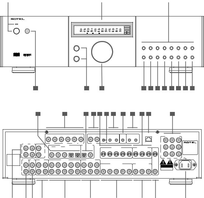
1:Controls and Connections Bedienelemente und Anschlüsse Controlli e Collegamenti
1 |
|
2 |
|
3 |
SURROUND SOUND PROCESSOR
RSP-976
STANDBY |
VIDEO 1 REC |
RBDS RDS |
RT EON TP TA PTY |
TAPE 2M |
ST TUNED AUTO MEMORY PRESET |
O S D |
|
|
VIDEO2 |
|
|
|
|
OPTICAL |
|
|
VIDEO3 |
|
|
|
|
COAXIAL |
|
|
VD4AUX |
|
|
|
|
1 |
2 |
|
SOURCE |
dts |
DIGITAL Pro Logic |
3Stereo |
DSP MODE 5.1ch D.RANGE |
3 |
4 |
TREBLE
|
CD |
TUNER |
TAPE |
VIDEO1 VIDEO2 VIDEO3 VIDEO4 VIDEO5 |
|
BASS |
|
3 |
PRO |
5.1CH DYNAMIC |
|
2CH |
STEREO |
LOGIC |
DSP INPUT RANGE ZONE REC |
||
|
4 |
5 |
6 |
7 |
8 |
9 |
10 |
11 |
12 |
13 |
14 |
15 |
16 |
17 |
18 19 |
20 |
21 |
22 |
23 |
24 |
25 |
26 |
This device complies with Part 15 of the FCC Rules. |
|
|
5.1 CH INPUT |
|
|
|
|
|
|||
R |
L |
R |
L |
|
|
|
R |
L |
|||
Operation is subject to the following two conditions: |
|
|
|
||||||||
(1) This device may not cause harmful interference, and |
|
|
|
|
|
|
|
|
|||
(2) this device must accept any interference received, |
|
|
|
|
|
|
|
|
|||
including interference that may cause undesired operation. |
|
|
|
|
|
|
|
|
|||
|
FRONT |
REAR |
|
FRONT |
|
REAR |
|
CENTER |
SUB |
ZONE |
|
|
|
|
|
WOOFER |
OUT |
|
|||||
|
|
|
|
|
DIGITAL INPUT |
|
|
DIGITAL OUPUT |
|
||
|
L |
|
CENTER |
|
COAXIAL |
|
|
OPTICAL |
|
|
|
|
|
1 |
2 |
3 |
1 |
2 |
OPTICAL |
COAXIAL |
|
||
OUTPUT |
|
|
|
|
|
|
|
|
|
|
|
|
R |
|
SUB |
|
|
|
|
|
|
|
|
Manufactured under license |
|
WOOFER |
|
|
|
|
|
|
|
|
|
|
|
|
|
|
|
|
|
|
|
||
from Digital Theater System, |
|
|
|
|
|
|
|
|
|
|
|
Inc. US Pat. No. 5,451,242 |
|
|
|
|
|
|
|
|
|
|
|
and other world-wide patents, |
TUNER |
CD |
TAPE |
|
VIDEO IN |
|
|
|
VIDEO OUT |
|
|
DTS Digital surround", are |
|
|
|
|
|
||||||
issues and pending. "DTS", |
|
|
|
|
|
|
|
|
|
|
|
trademarks of Digital Theater |
|
IN |
OUT |
1 |
2 |
3 |
4 |
5 |
1 |
2 |
3 |
System, Inc. Copyright 1996 |
|
|
|
|
|
|
|
|
|
||
Digital Theater System, Inc. |
|
|
|
|
|
|
|
|
|
|
|
All rights reserved. |
L |
|
|
|
|
|
|
|
|
|
|
|
|
|
|
|
|
|
|
|
|
|
|
INPUT
R
Manufactured under license from Dolby Laboratories Licensing Corporation. "Dolby", "Pro Logic" and the double-D symbol are trademarks of Dolby Laboraties Licensing Corporation. Confidential unpublished works © 1992-1997 Dolby Laboraties, Inc. All rights reserved.
ZONE |
|
IR OUT |
EXT |
12V TRIGGER |
COMPUTER |
|
|
|||
|
|
I/O |
COMPONENT VIDEO |
|
||||||
REM. IN |
1 |
2 |
REM IN |
1 OUT |
2 |
|
|
|
||
|
|
|
|
|
|
|
|
1 |
|
|
|
|
|
|
|
|
|
|
IN |
|
SURROUND SOUND |
|
|
|
|
|
|
|
|
|
|
|
|
|
|
|
|
|
|
|
2 |
|
PROCESSOR |
|
|
S-VIDEO IN |
|
|
S-VIDEO OUT |
|
|
MODEL NO. RSP-976 |
||
|
|
|
|
|
|
|
POWER CONSUMPTION: |
|||
1 |
2 |
3 |
4 |
5 |
1 |
2 |
3 |
|
|
40 WATTS |
|
|
|
||||||||
|
|
|
|
|
|
|
|
MON. |
|
RSP-976 |
|
|
|
|
|
|
|
|
OUT |
|
V2.0 |
|
|
|
|
|
|
|
|
CR |
CB |
Y |
|
|
COMPOSITE IN |
|
COMPOSITE OUT |
MONITOR |
|
|
|||
|
|
|
OUT |
|
|
|||||
1 |
2 |
3 |
4 |
5 |
1 |
2 |
3 |
CAUTION |
|
|
RISK OF ELECTRIC SHOCK |
|
|||||||||
|
|
|
|
|
|
|
|
DO NOT OPEN |
|
|
|
|
|
|
|
|
|
|
WARNING: SHOCK HAZARD, DO NOT OPEN |
||
|
|
|
|
|
|
|
|
AVIS: RISQUE DE CHOC ELECTRIQUE–NE PAS OUVRIR |
||
|
|
|
WARNING:TO REDUCE THE RISK OF FIRE OR ELECTICAL SHOCK, |
|
|
|
|
|||
|
|
|
DO NOT EXPOSE THIS EQUIPMENT TO RAIN OR MOISTURE. |
|
|
|
||||
27 |
|
28 |
|
29 |
|
30 |
|
31 |
|
32 |
|
33 |
|
34 |
|
35 |
|
36 |
5
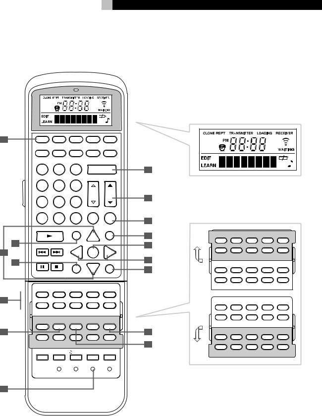
2:RR-969 Remote Fernbedienung RR-969 Comando a Distanza Rr-969
A |
|
AUD |
TV |
SAT |
VCR |
DVD |
|
|
|
CD |
TUN |
AV 1 |
AV 2 |
AV 3 |
|
|
|
1 |
2 |
3 |
POWER |
H |
|
|
|
4 |
5 |
6 |
|
|
|
|
|
|
|
|
CH |
VOL |
I |
|
|
7 |
8 |
9 |
|
|
|
|
|
|
|
|
|||
|
|
|
|
|
INPUT |
|
|
|
|
+10 |
0 |
X |
BAND |
MUTE |
J |
|
|
|
|
|
|
|
|
|
|
PLAY |
GUIDE |
|
MENU |
|
|
|
|
|
|
C |
UP |
M |
K |
|
B |
|
|
|
|
|
|
|
TRACK |
|
|
OSD |
L |
||
|
|
|
|
|
|||
C |
|
|
|
- |
ENT |
+ |
|
|
D |
PAUSE |
STOP |
|
|
PREV CH |
M |
|
|
|
|
DWN |
|
||
|
|
|
|
S |
R |
N |
|
|
|
|
|
|
|||
|
|
|
|
SEARCH – |
|
SEARCH + |
|
|
|
TV/VCR |
|
|
|
|
|
|
|
PIP |
SWAP |
POS |
ANT |
MODE |
|
|
|
CD |
TUN |
PH |
TAPE1 |
TAPE2 |
|
E |
|
|
|
|
|
|
|
|
|
V1 |
V2 |
V3 |
V4 |
V5 |
|
|
|
INPUT1 |
INPUT2 |
INPUT3 |
TV/VCR |
RECORD |
|
|
|
FM |
DIRECTAUDIO |
ANGLE |
SUBTITLE |
FM |
|
|
|
SETUPMONO |
NARROWTITLE |
|
|||
FILTER |
EXT IN |
BACKZONE |
PRESETSCAN |
SUR + |
|
F |
|
|
|
|
O |
SHIFT |
ZONEPTY |
SELECTTA |
DYNMCTP |
DISPLAY |
|
ZOOM |
CLEAR |
MODE |
CONDITION |
DISPLAY |
P |
DVDTUNER |
|
|
|
|
|
MACRO |
TIME/ALM |
/ CLONE |
EDIT |
LEARN |
|
|
CLEAR |
LANG |
PRELOAD |
RESET |
|
|
|
PAGE 1/2 |
|
|
|
CD |
|
|
|
|
DISC1 |
DISC2 |
DISC3 |
DISC4 |
DISC5 |
CD |
TUN |
PH |
TAPE1 |
TAPE2 |
V1 |
V2 |
V3 |
V4 |
V5 |
PROGRAM |
RANDOM |
REPEAT |
DISC |
DISC+ |
SETUP |
AUDIO |
ANGLE |
SUBTITLE |
TITLE |
FILTER |
EXT IN |
ZONE |
PRESET |
SUR + |
SHIFT |
PTY |
TA |
TP |
DISPLAY |
ZOOM |
CLEAR |
MODE |
CONDITION |
|
DVD |
|
|
|
|
TV/VCR |
|
|
|
|
PIP |
SWAP |
POS |
ANT |
MODE |
CD |
TUN |
PH |
TAPE1 |
TAPE2 |
V1 |
V2 |
V3 |
V4 |
V5 |
INPUT1 |
INPUT2 |
INPUT3 |
TV/VCR |
RECORD |
FM |
DIRECT |
|
|
FM |
MONO |
|
|
NARROW |
|
FILTER |
EXT IN |
ZONE |
PRESET |
SUR + |
SHIFT |
PTY |
TA |
TP |
DISPLAY |
TUNER |
|
|
|
|
G

RSP-976 |
6 |
3: Outputs • Ausgangsanschlüsse • Collegamenti d’Uscita
AMPLIFIER
VERSTÄRKER
SUBWOOFER
FRONT |
REAR |
|
L |
CENTER |
|
R |
SUB |
|
WOOFER |
||
|
This device complies with Part 15 of the FCC Rules. |
|
|
5.1 CH INPUT |
|
|
|
Operation is subject to the following two conditions: |
R |
L |
R |
L |
R |
L |
(1)This device may not cause harmful interference, and
(2)this device must accept any interference received, including interference that may cause undesired operation.
L
OUTPUT
R
Manufactured under license from Digital Theater System, Inc. US Pat. No. 5,451,242 and other world-wide patents, issues and pending. "DTS", DTS Digital surround", are trademarks of Digital Theater System, Inc. Copyright 1996 Digital Theater System, Inc.
All rights reserved.
L
INPUT
R
FRONT |
REAR |
|
FRONT |
|
REAR |
|
CENTER |
SUB |
ZONE |
|
|
|
|
WOOFER |
OUT |
|
|||||
|
|
|
|
|
DIGITAL INPUT |
|
|
DIGITAL OUPUT |
|
|
|
|
CENTER |
|
COAXIAL |
|
OPTICAL |
|
|
|
|
|
|
1 |
2 |
3 |
1 |
2 |
OPTICAL |
COAXIAL |
|
|
|
|
SUB |
|
|
|
|
|
|
|
|
|
|
WOOFER |
|
|
|
|
|
|
|
|
TUNER |
CD |
TAPE |
|
|
VIDEO IN |
|
|
|
VIDEO OUT |
|
|
IN |
OUT |
1 |
2 |
3 |
4 |
5 |
1 |
2 |
3 |
Manufactured under license from Dolby Laboratories Licensing Corporation. "Dolby", "Pro Logic" and the double-D symbol are trademarks of Dolby Laboraties Licensing Corporation. Confidential unpublished works © 1992-1997 Dolby Laboraties, Inc. All rights reserved.
ROTEL RSP-976
ZONE |
|
IR OUT |
EXT |
12V TRIGGER |
COMPUTER |
|
|
|||
|
|
I/O |
COMPONENT VIDEO |
|
||||||
REM. IN |
1 |
2 |
REM IN |
1 OUT |
2 |
|
|
|
||
|
|
|
|
|
|
|
|
1 |
|
|
|
|
|
|
|
|
|
|
IN |
|
SURROUND SOUND |
|
|
|
|
|
|
|
|
|
|
|
|
|
|
|
|
|
|
|
2 |
|
PROCESSOR |
|
|
S-VIDEO IN |
|
|
S-VIDEO OUT |
|
|
MODEL NO. RSP-976 |
||
|
|
|
|
|
|
|
POWER CONSUMPTION: |
|||
1 |
2 |
3 |
4 |
5 |
1 |
2 |
3 |
|
|
40 WATTS |
|
|
|
||||||||
|
|
|
|
|
|
|
|
MON. |
|
RSP-976 |
|
|
|
|
|
|
|
|
OUT |
|
V2.0 |
|
|
|
|
|
|
|
|
CR |
CB |
Y |
|
|
COMPOSITE IN |
|
COMPOSITE OUT |
MONITOR |
|
|
|||
|
|
|
OUT |
|
|
|||||
1 |
2 |
3 |
4 |
5 |
1 |
2 |
3 |
CAUTION |
|
|
RISK OF ELECTRIC SHOCK |
|
|||||||||
|
|
|
|
|
|
|
|
DO NOT OPEN |
|
|
|
|
|
|
|
|
|
|
WARNING: SHOCK HAZARD, DO NOT OPEN |
||
|
|
|
|
|
|
|
|
AVIS: RISQUE DE CHOC ELECTRIQUE–NE PAS OUVRIR |
||
|
|
|
WARNING:TO REDUCE THE RISK OF FIRE OR ELECTICAL SHOCK, |
|
|
|
|
|||
|
|
|
DO NOT EXPOSE THIS EQUIPMENT TO RAIN OR MOISTURE. |
|
|
|
||||
TV |
Alternate Video Connections

7
4: Inputs • Eingangsanschlüsse • Collegamenti d’Ingresso
DVD
|
L |
S-VIDEO |
COMPONENT VIDEO |
|
|
|
|
|
|
||
|
|
|
CR |
CB |
Y |
|
R |
COMPOSITE |
|
|
|
DIGITAL |
AUDIO |
VIDEO |
|
|
|
OUTPUT |
OUTPUT |
|
|
|
|
OUTPUTS |
|
|
|
||
|
|
|
|
|
|
This device complies with Part 15 of the FCC Rules. |
|
|
5.1 CH INPUT |
|
|
|
Operation is subject to the following two conditions: |
R |
L |
R |
L |
R |
L |
(1)This device may not cause harmful interference, and
(2)this device must accept any interference received, including interference that may cause undesired operation.
L
OUTPUT
R
Manufactured under license from Digital Theater System, Inc. US Pat. No. 5,451,242 and other world-wide patents, issues and pending. "DTS", DTS Digital surround", are trademarks of Digital Theater System, Inc. Copyright 1996 Digital Theater System, Inc.
All rights reserved.
L
INPUT
R
FRONT |
REAR |
|
FRONT |
|
REAR |
|
CENTER |
SUB |
ZONE |
|
|
|
|
WOOFER |
OUT |
|
|||||
|
|
|
|
|
DIGITAL INPUT |
|
|
DIGITAL OUPUT |
|
|
|
|
CENTER |
|
COAXIAL |
|
OPTICAL |
|
|
|
|
|
|
1 |
2 |
3 |
1 |
2 |
OPTICAL |
COAXIAL |
|
|
|
|
SUB |
|
|
|
|
|
|
|
|
|
|
WOOFER |
|
|
|
|
|
|
|
|
TUNER |
CD |
TAPE |
|
|
VIDEO IN |
|
|
|
VIDEO OUT |
|
|
IN |
OUT |
1 |
2 |
3 |
4 |
5 |
1 |
2 |
3 |
Manufactured under license from Dolby Laboratories Licensing Corporation. "Dolby", "Pro Logic" and the double-D symbol are trademarks of Dolby Laboraties Licensing Corporation. Confidential unpublished works © 1992-1997 Dolby Laboraties, Inc. All rights reserved.
ROTEL RSP-976
ZONE |
|
IR OUT |
EXT |
12V TRIGGER |
COMPUTER |
|
|
|||
|
|
I/O |
COMPONENT VIDEO |
|
||||||
REM. IN |
1 |
2 |
REM IN |
1 OUT |
2 |
|
|
|
||
|
|
|
|
|
|
|
|
1 |
|
|
|
|
|
|
|
|
|
|
IN |
|
SURROUND SOUND |
|
|
|
|
|
|
|
|
|
|
|
|
|
|
|
|
|
|
|
2 |
|
PROCESSOR |
|
|
S-VIDEO IN |
|
|
S-VIDEO OUT |
|
|
MODEL NO. RSP-976 |
||
|
|
|
|
|
|
|
POWER CONSUMPTION: |
|||
1 |
2 |
3 |
4 |
5 |
1 |
2 |
3 |
|
|
40 WATTS |
|
|
|
||||||||
|
|
|
|
|
|
|
|
MON. |
|
RSP-976 |
|
|
|
|
|
|
|
|
OUT |
|
V2.0 |
|
|
|
|
|
|
|
|
CR |
CB |
Y |
|
|
COMPOSITE IN |
|
COMPOSITE OUT |
MONITOR |
|
|
|||
|
|
|
OUT |
|
|
|||||
1 |
2 |
3 |
4 |
5 |
1 |
2 |
3 |
CAUTION |
|
|
RISK OF ELECTRIC SHOCK |
|
|||||||||
|
|
|
|
|
|
|
|
DO NOT OPEN |
|
|
|
|
|
|
|
|
|
|
WARNING: SHOCK HAZARD, DO NOT OPEN |
||
|
|
|
|
|
|
|
|
AVIS: RISQUE DE CHOC ELECTRIQUE–NE PAS OUVRIR |
||
|
|
|
WARNING:TO REDUCE THE RISK OF FIRE OR ELECTICAL SHOCK, |
|
|
|
|
|||
|
|
|
DO NOT EXPOSE THIS EQUIPMENT TO RAIN OR MOISTURE. |
|
|
|
||||
VCR • VIDEORECORDER
L
|
|
|
S-VIDEO |
|
|
R |
|
LINE |
REC |
|
COMPOSITE |
LINE |
REC |
||
OUT |
IN |
OUT |
IN |
AUDIO |
|
VIDEO |
|
TAPE
L
R
LINE REC
OUT IN
CD
L
R
ANALOG
OUTPUT
AM/FM
L
R
Alternate Video Connections

RSP-976 |
8 |
5: Zone 2 Connections • Anschlußdiagramm für den Zone 2-Betrieb • Collegamenti Zona 2
AM/FM
CD
This device complies with Part 15 of the FCC Rules. |
|
|
5.1 CH INPUT |
|
|
|
|
|
|||
R |
L |
R |
L |
|
|
|
R |
L |
|||
Operation is subject to the following two conditions: |
|
|
|
||||||||
(1) This device may not cause harmful interference, and |
|
|
|
|
|
|
|
|
|||
(2) this device must accept any interference received, |
|
|
|
|
|
|
|
|
|
||
including interference that may cause undesired operation. |
|
|
|
|
|
|
|
|
|||
|
FRONT |
REAR |
|
FRONT |
|
REAR |
|
CENTER |
SUB |
ZONE |
|
|
|
|
|
WOOFER |
OUT |
|
|||||
|
|
|
|
|
DIGITAL INPUT |
|
|
DIGITAL OUPUT |
|
||
|
L |
|
CENTER |
|
COAXIAL |
|
|
OPTICAL |
|
|
|
|
|
1 |
2 |
3 |
1 |
2 |
OPTICAL |
COAXIAL |
|
||
OUTPUT |
|
|
|
|
|
|
|
|
|
|
|
|
R |
|
SUB |
|
|
|
|
|
|
|
|
Manufactured under license |
|
WOOFER |
|
|
|
|
|
|
|
|
|
|
|
|
|
|
|
|
|
|
|
||
from Digital Theater System, |
|
|
|
|
|
|
|
|
|
|
|
Inc. US Pat. No. 5,451,242 |
|
|
|
|
|
|
|
|
|
|
|
and other world-wide patents, |
TUNER |
CD |
TAPE |
|
VIDEO IN |
|
|
|
VIDEO OUT |
|
|
DTS Digital surround", are |
|
|
|
|
|
||||||
issues and pending. "DTS", |
|
|
|
|
|
|
|
|
|
|
|
trademarks of Digital Theater |
|
IN |
OUT |
1 |
2 |
3 |
4 |
5 |
1 |
2 |
3 |
System, Inc. Copyright 1996 |
|
|
|
|
|
|
|
|
|
||
Digital Theater System, Inc. |
|
|
|
|
|
|
|
|
|
|
|
All rights reserved. |
L |
|
|
|
|
|
|
|
|
|
|
|
|
|
|
|
|
|
|
|
|
|
|
INPUT
R
Manufactured under license from Dolby Laboratories Licensing Corporation. "Dolby", "Pro Logic" and the double-D symbol are trademarks of Dolby Laboraties Licensing Corporation. Confidential unpublished works © 1992-1997 Dolby Laboraties, Inc. All rights reserved.
ROTEL RSP-976
ZONE |
|
|
EXT |
12V TRIGGER |
COMPUTER |
|
|
|||
|
IR OUT |
|
I/O |
COMPONENT VIDEO |
|
|||||
REM. IN |
1 |
2 |
REM IN |
1 OUT |
2 |
|
|
|
||
|
|
|
|
|
|
|
|
1 |
|
|
|
|
|
|
|
|
|
|
IN |
|
SURROUND SOUND |
|
|
|
|
|
|
|
|
2 |
|
PROCESSOR |
|
|
S-VIDEO IN |
|
|
S-VIDEO OUT |
|
|
MODEL NO. RSP-976 |
||
|
|
|
|
|
|
|
POWER CONSUMPTION: |
|||
1 |
2 |
3 |
4 |
5 |
1 |
2 |
3 |
|
|
40 WATTS |
|
|
|
||||||||
|
|
|
|
|
|
|
|
MON. |
|
RSP-976 |
|
|
|
|
|
|
|
|
OUT |
|
V2.0 |
|
|
|
|
|
|
|
|
CR |
CB |
Y |
|
|
COMPOSITE IN |
|
COMPOSITE OUT |
MONITOR |
|
|
|||
|
|
|
OUT |
|
|
|||||
1 |
2 |
3 |
4 |
5 |
1 |
2 |
3 |
CAUTION |
|
|
RISK OF ELECTRIC SHOCK |
|
|||||||||
|
|
|
|
|
|
|
|
DO NOT OPEN |
|
|
|
|
|
|
|
|
|
|
WARNING: SHOCK HAZARD, DO NOT OPEN |
||
|
|
|
|
|
|
|
|
AVIS: RISQUE DE CHOC ELECTRIQUE–NE PAS OUVRIR |
||
|
|
|
WARNING:TO REDUCE THE RISK OF FIRE OR ELECTICAL SHOCK, |
|
|
|
|
|||
|
|
|
DO NOT EXPOSE THIS EQUIPMENT TO RAIN OR MOISTURE. |
|
|
|
||||
AMPLIFIER • VERSTÄRKER
ZONE 2 IR
9
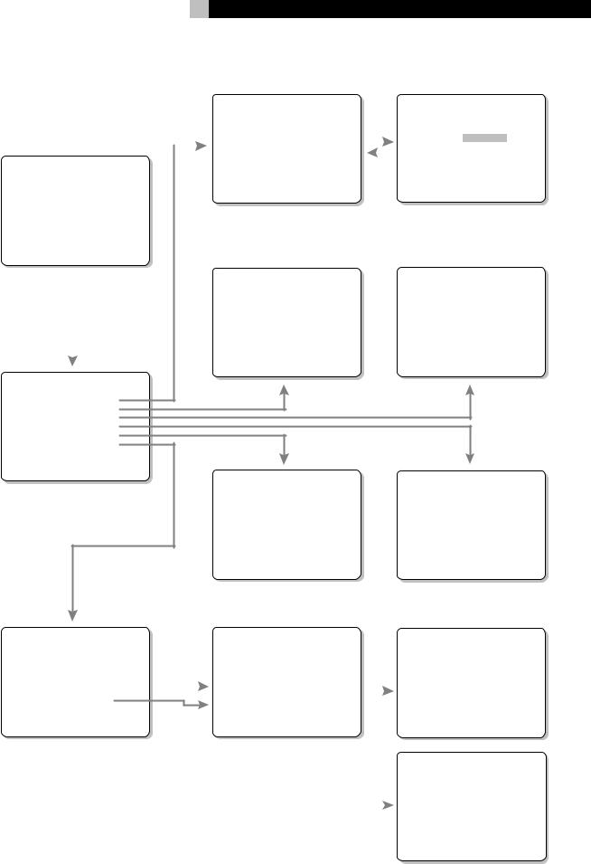
6: On-Screen Menus • On-Screen-Menüsystem • Menu On-Screen
|
|
|
|
|
INPUT SETUP |
|
|
|
|
|
|
INPUT SETUP |
||||
|
|
|
|
|
LISTEN: Video 2 |
|
|
|
|
|
|
LISTEN: Video 2 |
||||
|
|
|
|
|
INPUT LABEL: _ _ _ _ |
_ |
|
|
|
|
|
INPUT LABEL: |
_ _ _ _ _ |
|
||
|
|
|
|
|
INPUT: Coaxial |
1 |
|
|
|
|
|
INPUT: Coaxial 1 |
||||
|
|
|
|
|
|
|
|
|
|
|||||||
|
|
|
|
|
INPUT MODE: Dolby 3 |
Stereo |
|
|
|
|
|
INPUT MODE: Dolby 3 Stereo |
||||
SYSTEM STATUS |
|
|
|
DIGITAL OUT: Coaxial |
1 |
|
|
|
|
|
DIGITAL OUT: Coaxial 1 |
|||||
LISTEN: Tuner |
|
|
|
ENT KEY=MAIN MENU |
UP KEY=up |
|
|
|
|
|
ENT KEY=ENTER |
|||||
RECORD: CD |
|
|
|
+/– KEY=change |
DWN KEY=down |
|
|
|
|
|
+/– KEY=char |
|||||
MODE: Dolby Digital |
|
|
|
|
|
|
|
|
|
|
|
|
|
|
|
|
INPUT: Coaxial 1 |
|
|
|
|
|
|
|
|
|
|
|
|
|
|
|
|
VOLUME: 65 |
|
|
|
|
|
|
|
|
|
|
|
|
|
|
|
|
ENT KEY=MAIN MENU |
|
|
|
|
|
|
|
|
|
|
|
|
|
|
|
|
OSD KEY=EXIT |
|
|
|
|
|
|
|
|
|
|
|
|
|
|
|
|
|
|
|
|
|
|
|
|
|
|
|
|
|
|
|
||
|
|
|
|
|
SPEAKER SETUP |
|
|
|
|
|
|
DELAY SETUP |
||||
|
|
|
|
|
|
|
|
|
|
|
|
|
Dolby |
Dolby |
||
|
|
|
|
|
FRONT: Large |
|
|
|
|
|
|
Digital Pro Logic |
||||
|
|
|
|
|
CENTER: Large |
|
|
|
|
|
|
CENTER: 1ms |
|
|
||
|
|
|
|
|
SURROUND: Large |
|
|
|
|
|
|
|
|
|||
|
|
|
|
|
SUBWOOFER: Yes |
|
|
|
|
|
R SURROUND: 15ms |
30ms |
||||
|
|
|
|
|
|
|
|
|
|
|
|
L SURROUND: 15ms |
30ms |
|||
|
|
|
|
|
ENT KEY=MAIN MENU |
UP KEY=up |
|
|
|
|
|
ENT KEY=MAIN MENU |
UP KEY=up |
|||
|
|
|
|
|
|
|
|
|
|
|||||||
|
|
|
|
|
+/– KEY=change |
DWN KEY=down |
|
|
|
|
|
+/– KEY=change |
DWN KEY=down |
|||
|
|
|
|
|
|
|
|
|
|
|
|
|
|
|
|
|
MAIN MENU |
|
|
|
|
|
|
|
|
|
|
|
|
|
|
|
|
INPUT: Setup
SPEAKER: Setup
DELAY: Setup
TEST TONE: Setup
SUB LEVEL: Setup
OTHER: Setup
ENT KEY=ENTER
UP KEY=up DWN KEY=down
SUB LEVEL |
|
TEST TONE |
|
DOLBY: +1 |
LEFT: +1dB |
||
CENTER: -1dB |
|||
DTS: -2 |
RIGHT: +1dB |
||
STEREO: +5 |
R SURROUND: +5dB |
||
MUSIC: +3 |
L SURROUND: +4dB |
||
|
|
SUBWOOFER: +9dB |
|
ENT KEY=MAIN MENU |
ENT KEY=MAIN MENU |
UP KEY=up |
|
+/– KEY=change |
+/– KEY=change |
DWN KEY=down |
|
OTHER OPTIONS |
|
|
|
|
OTHER OPTIONS |
|
|
|
|
|
||||
RECORD: CD |
|
|
|
|
RECORD: CD |
|
|
|
Reset to factory |
|||||
DYNAMIC: Max |
|
|
|
|
DYNAMIC: Max |
|
|
|
default settings: |
|||||
5.1CH: Off |
|
|
|
|
5.1CH: Off |
|
|
|
|
|
||||
POWER: Direct |
|
|
|
|
POWER: Direct |
|
|
|
|
|
||||
RESET: Setup |
|
|
|
|
|
RESET: Setup |
|
|
|
|
YES = ENT KEY |
|||
ZONE2: Setup |
|
|
|
|
ZONE2: Setup |
|
|
|
|
NO = DWN KEY |
||||
ENT KEY=MAIN MENU |
UP KEY=up |
|
|
|
|
ENT KEY=ENTER |
|
|
|
|||||
|
|
|
|
|
|
|
|
|
||||||
+/– KEY=change |
DWN KEY=down |
|
|
|
|
UP KEY=up DWN KEY=down |
|
|
|
|
|
|||
|
|
|
|
|
|
|
|
|
|
|
|
|
|
|
|
|
|
|
|
|
|
|
|
|
|
|
|
ZONE2 SETUP |
|
|
|
|
|
|
|
|
|
|
|
|
|
|
SOURCE: CD |
|
|
|
|
|
|
|
|
|
|
|
|
|
|
VOLUME SETUP: Variable |
|
|
|
|
|
|
|
|
|
|
|
|
|
|
VOLUME: 20 |
|
|
|
|
|
|
|
|
|
|
|
|
|
|
||
|
|
|
|
|
|
|
|
|
|
|
|
|
ENT KEY=MAIN MENU |
UP KEY=up |
|
|
|
|
|
|
|
|
|
|
|
|
|
+/– KEY=change |
DWN KEY=down |

RSP-976 Surround Sound Processor |
10 |
Contents |
|
Surround Sound Controls |
13 |
Zone 2 Connection and Operation |
17 |
||||||||||||||||||||||||||||||||||||||||||||||||||||||||||||||||||||||||
|
|
|
|
|
|
|
|
|
|
|
|
|
|
|
|
|
|
|
|
|
|
|
|
|
|||||||||||||||||||||||||||||||||||||||||||||||||||||
|
|
|
|
|
|
|
|
|
|
|
|
|
|
|
|
|
|
|
|
|
|
|
|
|
|
|
|
|
|
|
|
|
|
|
|
|
|
|
|
|
|
|
|
|
|
|
|
|
|
|
|
|
|
|
|
|
|
|
|
|
|
|
|
|
|
|
|
|
|
|
|
|
|
|
|
|
|
|
|
|
|
|
|
|
|
|
|
|
|
|
|
|
|
|
|
|
|
|
|
|
|
|
PRO LOGIC Button |
|
|
|
|
|
|
|
|
|
|
|
|
|
|
|
|
|
|
|
|
|
|
|
13 |
Zone 2 Power On/Off Operation |
17 |
||||||||||||||||||||||||||
|
|
|
|
|
|
|
|
|
|
|
|
|
|
|
|
|
|
|
|
|
|
|
|
|
|
|
|
|
|
|
|
|
|
|
|
|
|
|
|
|
|
|
|
|
|
|
|
|
|
|
|
|
|
||||||||||||||||||||||||
Boxed numbers refer to RSP-976 illustration. |
|
3 STEREO Button |
|
|
|
|
|
|
|
|
|
|
|
|
|
|
|
|
|
|
|
|
|
|
|
|
13 |
Controlling Zone 2 from the Main Room |
|
||||||||||||||||||||||||||||||||||||||||||||||||
Boxed letters refer to RR-969 illustration. |
|
DSP Button |
|
|
|
|
|
|
|
|
|
|
|
|
|
|
|
|
|
|
|
|
|
|
|
|
|
|
|
|
|
|
|
|
13 |
ZONE Button |
|
|
|
|
|
|
|
|
|
|
|
|
|
|
17 |
||||||||||||||||||||||||||
|
|
|
|
|
|
|
|
|
|
|
|
|
|
|
|
|
|
|
|
|
|
|
|
|
|
|
|
|
|
|
|
|
|
|
|||||||||||||||||||||||||||||||||||||||||||
|
|
|
|
|
|
|
|
|
|
|
|
|
|
|
|
|
|
|
|
|
|
|
|
|
|
|
|
|
|
|
|
|
|||||||||||||||||||||||||||||||||||||||||||||
|
|
|
|
|
|
|
|
|
|
|
|
|
|
|
|
|
|
|
|
|
|
|
|
|
|
|
|
|
|
|
|
|
|
|
|
|
|
|
|
|
|
|
|
|
|
|
|
|
|
|
|
|
|
|
|
|
Controlling Zone 2 from the Remote Location |
18 |
|||||||||||||||||||
|
|
|
|
|
|
|
|
|
|
|
|
|
|
|
|
|
|
|
|
|
|
|
|
|
2CH Button |
|
|
|
|
|
|
|
|
|
|
|
|
|
|
|
|
|
|
|
|
|
|
|
|
|
|
|
|
|
|
|
13 |
||||||||||||||||||||
|
|
|
|
|
|
|
|
|
|
|
|
|
|
|
|
|
|
|
|
|
|
|
|
|
|
|
|
|
|
|
|
|
|
|
|
|
|
|
|
|
|
|
|
|
|
|
|
|
|
|
|
|
|
|
|
||||||||||||||||||||||
Cautions |
2 |
SUR+ Button |
|
|
|
|
|
|
|
|
|
|
|
|
|
|
|
|
|
|
|
|
|
|
|
|
|
|
|
|
|
14 |
Zone 2 Audio Outputs |
|
|
|
|
|
|
|
|
|
18 |
||||||||||||||||||||||||||||||||||
|
|
|
|
|
|
|
|
|
|
|
|
|
|
|
|
|
|
|
|
|
|
|
|
|
|
|
|
|
|
|
|
||||||||||||||||||||||||||||||||||||||||||||||
|
|
|
|
||||||||||||||||||||||||||||||||||||||||||||||||||||||||||||||||||||||||||
|
|
|
|
|
|
|
|
|
|
|
|
|
|
|
|
|
|
|
|
|
|
|
|
|
|
|
|
|
|
|
|
||||||||||||||||||||||||||||||||||||||||||||||
1: Controls and Connections |
4 |
Speaker Level Adjustment |
|
ZONE REM. IN Jack |
|
|
|
|
|
|
|
|
18 |
||||||||||||||||||||||||||||||||||||||||||||||||||||||||||||||||
|
|
||||||||||||||||||||||||||||||||||||||||||||||||||||||||||||||||||||||||||||
|
|
|
|
|
|
|
|
|
|
|
|
|
|
|
|
|
|
|
|
|
|
|
|
|
|
|
|
|
|
|
|
|
|
|
|
|
|
|
|
|
|
||||||||||||||||||||||||||||||||||||
2: RR-969 Remote |
5 |
Selection Buttons |
|
|
|
|
|
|
|
|
|
|
|
|
|
|
|
|
|
|
|
|
|
|
|
|
|
IR OUT Jacks |
|
|
|
|
|
|
|
|
|
|
18 |
||||||||||||||||||||||||||||||||||||||
3: Outputs |
6 |
UP/DOWN Buttons |
|
|
|
|
|
|
|
|
|
|
|
|
|
|
|
|
|
|
|
|
|
|
14 |
On-Screen Display / Configuration |
19 |
||||||||||||||||||||||||||||||||||||||||||||||||||
|
|
|
|||||||||||||||||||||||||||||||||||||||||||||||||||||||||||||||||||||||||||
DYNAMIC RANGE Button |
|
|
|
|
|
|
|
|
|
|
|
|
|
|
|
|
|
||||||||||||||||||||||||||||||||||||||||||||||||||||||||||||
4: Inputs |
7 |
|
|
|
|
|
|
|
|
|
|
|
|
|
|
|
|
|
|||||||||||||||||||||||||||||||||||||||||||||||||||||||||||
|
|
|
|
|
|
|
|
|
|
|
|
|
|
|
|
|
Navigation Buttons |
|
|
|
|
|
|
|
|
|
|
|
19 |
||||||||||||||||||||||||||||||||||||||||||||||||
|
|
|
|
|
|
|
|
|
|
|
|
|
|
|
|
|
|
|
|
|
|
|
|
|
|
|
|
||||||||||||||||||||||||||||||||||||||||||||||||||
DWN Button |
|
|
|
|
|
|
|
|
|
|
|
|
|
|
|
|
|
|
|
|
|
|
|
|
|
|
|
|
|
|
14 |
|
|
|
|
|
|
|
|
|
|
|
|||||||||||||||||||||||||||||||||||
|
|
|
|
|
|
|
|
|
|
|
|
|
|
|
|
|
|
|
|
|
|
|
|
|
|
|
|
|
|
|
|
|
|
|
|
|
|
|
|
|
|||||||||||||||||||||||||||||||||||||
5: Zone 2 Connections |
8 |
|
|
|
|
|
|
|
|
|
|
|
|
|
|
|
|
|
|
|
|
|
|
|
|
|
|
|
|
|
|
SYSTEM STATUS Menu |
19 |
||||||||||||||||||||||||||||||||||||||||||||
Connections: Overview |
14 |
||||||||||||||||||||||||||||||||||||||||||||||||||||||||||||||||||||||||||||
|
|
|
|
|
|
|
|
|
|
|
|
|
|
|
|
|
|
|
|
|
|
|
|
|
|||||||||||||||||||||||||||||||||||||||||||||||||||||
6: On-Screen Menus |
9 |
MAIN Menu |
19 |
||||||||||||||||||||||||||||||||||||||||||||||||||||||||||||||||||||||||||
|
|
|
|
|
|
|
|
|
|
|
|
|
|
|
|
|
|
|
|
|
|
|
|
|
|
|
|
|
|
|
|
|
|
|
|
|
|
|
|
|
|
|
|
|
|
|
|
|
|
|
|
|
|
|
|
|
|
|
|
|
|||||||||||||||||
About Rotel ......................................... |
11 |
Audio Source Connections ..................... |
14 |
INPUT Menu |
19 |
||||||||||||||||||||||||||||||||||||||||||||||||||||||||||||||||||||||||
Getting Started |
11 |
TUNER Inputs |
|
|
|
|
|
|
|
|
|
|
|
|
|
|
|
|
|
|
|
|
|
|
|
|
14 |
SPEAKER SETUP Menu |
20 |
||||||||||||||||||||||||||||||||||||||||||||||||
CD Inputs |
|
|
|
|
|
|
|
|
|
|
|
|
|
|
|
|
|
|
|
|
|
|
|
|
|
|
|
|
|
|
|
|
|
14 |
|||||||||||||||||||||||||||||||||||||||||||
|
|
|
|
|
|
|
|
|
|
|
|
|
|
|
|
|
|
|
|
|
|
|
|
|
|
|
|
|
|
|
|
|
DELAY SETUP Menu |
21 |
|||||||||||||||||||||||||||||||||||||||||||
Key Features |
11 |
|
|
|
|
|
|
|
|
|
|
|
|
|
|
|
|
|
|
|
|
|
|
|
|
|
|
||||||||||||||||||||||||||||||||||||||||||||||||||
TAPE Inputs and Outputs |
|
|
|
|
|
|
|
|
|
|
|
|
|
|
|
|
14 |
||||||||||||||||||||||||||||||||||||||||||||||||||||||||||||
Unpacking |
11 |
|
|
|
|
|
|
|
|
|
|
|
|
|
|
|
|
SUBWOOFER LEVEL Menu |
21 |
||||||||||||||||||||||||||||||||||||||||||||||||||||||||||
|
|
|
|
|
|
|
|
|
|
|
|
|
|
|
|
|
|
|
|
|
|
|
|
|
|
|
|
|
|
|
|
|
|
|
|
||||||||||||||||||||||||||||||||||||||||||
|
|
|
|
|
|
|
|
|
|
|
|
|
|
|
|
|
|
|
|
|
|
|
|
|
|
|
|
|
|
|
|
|
|
|
|
|
|
|
|
|
|
|
|
|
|
|
|
|
|
|
|
||||||||||||||||||||||||||
Placement |
11 |
Video Source Inputs .............................. |
15 |
TEST TONE Menu |
21 |
||||||||||||||||||||||||||||||||||||||||||||||||||||||||||||||||||||||||
RR-969 Remote Control |
11 |
VIDEO 1–5 Audio Inputs |
|
|
|
|
|
|
|
|
|
|
|
|
|
|
|
15 |
OTHER OPTIONS Menu |
22 |
|||||||||||||||||||||||||||||||||||||||||||||||||||||||||
VIDEO 1–5 Composite Video Inputs |
|
|
|
|
|
|
15 |
RESET Menu |
22 |
||||||||||||||||||||||||||||||||||||||||||||||||||||||||||||||||||||
|
|
|
|
|
|
||||||||||||||||||||||||||||||||||||||||||||||||||||||||||||||||||||||||
Using the RR-969 |
|
|
|
|
|
|
|
|
|
|
|
|
11 |
|
|
|
|
|
|
||||||||||||||||||||||||||||||||||||||||||||||||||||||||||
|
|
|
|
|
|
|
|
|
|
|
|
||||||||||||||||||||||||||||||||||||||||||||||||||||||||||||||||||
|
|
|
|
|
|
|
|
|
|
|
|
VIDEO 1–5 S-Video Inputs |
|
|
|
|
|
|
|
|
|
|
|
15 |
ZONE 2 SETUP Menu |
22 |
|||||||||||||||||||||||||||||||||||||||||||||||||||
Programming the RR-969 |
|
|
|
|
11 |
|
|
|
|
|
|
|
|
|
|||||||||||||||||||||||||||||||||||||||||||||||||||||||||||||||
|
|
|
|
||||||||||||||||||||||||||||||||||||||||||||||||||||||||||||||||||||||||||
|
|
|
|
VIDEO 1–2 Component Video Inputs |
|
|
|
|
|
15 |
Specifications |
23 |
|||||||||||||||||||||||||||||||||||||||||||||||||||||||||||||||||
Basic Controls |
12 |
|
|
|
|
||||||||||||||||||||||||||||||||||||||||||||||||||||||||||||||||||||||||
|
|
||||||||||||||||||||||||||||||||||||||||||||||||||||||||||||||||||||||||||||
5.1 Channel Audio Inputs |
|
|
|
|
|
|
|
|
|
|
|
|
|
|
15 |
Audio |
23 |
||||||||||||||||||||||||||||||||||||||||||||||||||||||||||||
STANDBY/POWER Switch |
|
|
|
|
|
12 |
|
|
|
|
|
|
|
|
|
||||||||||||||||||||||||||||||||||||||||||||||||||||||||||||||
|
|
|
|
|
Video Source Outputs |
15 |
|||||||||||||||||||||||||||||||||||||||||||||||||||||||||||||||||||||||
|
|
|
|
|
Video |
23 |
|||||||||||||||||||||||||||||||||||||||||||||||||||||||||||||||||||||||
Remote Sensor |
|
|
|
|
|
|
|
|
|
|
|
|
|
|
|
|
12 |
||||||||||||||||||||||||||||||||||||||||||||||||||||||||||||
|
|
|
|
|
|
|
|
|
|
|
|
|
|
|
|
||||||||||||||||||||||||||||||||||||||||||||||||||||||||||||||
|
|
|
|
|
|
|
|
|
|
|
|
|
VIDEO 1–3 Audio Outputs |
|
|
|
|
|
|
|
|
|
|
|
|
15 |
General |
23 |
|||||||||||||||||||||||||||||||||||||||||||||||||
Front Panel Display |
|
|
|
|
|
|
|
|
|
|
12 |
|
|
|
|
|
|
|
|||||||||||||||||||||||||||||||||||||||||||||||||||||||||||
|
|
|
|
|
|
|
|
|
|
||||||||||||||||||||||||||||||||||||||||||||||||||||||||||||||||||||
|
|
|
|
|
|
|
|
|
|
VIDEO 1–3 Composite Video Outputs |
|
|
|
|
15 |
|
|
|
|
|
|
|
|
|
|
|
|
|
|
|
|
||||||||||||||||||||||||||||||||||||||||||||||
Volume Control |
|
|
|
|
|
|
|
|
|
|
|
|
|
|
|
12 |
|
|
|
|
|
|
|
|
|
|
|
|
|
|
|
|
|
|
|||||||||||||||||||||||||||||||||||||||||||
|
|
|
|
|
|
|
|
|
|
|
|
|
|
|
VIDEO 1–3 S-Video Outputs |
|
|
|
|
|
|
|
|
|
|
16 |
|
|
|
|
|
|
|
|
|
|
|
|
|
|
|
|
|||||||||||||||||||||||||||||||||||
MUTE Button |
|
|
|
|
|
|
|
|
|
|
|
|
|
|
|
|
|
|
|
12 |
|
|
|
|
|
|
|
|
|
|
|
|
|
|
|
|
|
|
|
||||||||||||||||||||||||||||||||||||||
|
|
|
|
|
|
|
|
|
|
|
|
|
|
|
|
|
|
|
|
|
|
|
|
|
|
|
|
|
|
|
|
|
|
|
|||||||||||||||||||||||||||||||||||||||||||
|
|
|
|
|
|
|
|
|
|
|
|
|
|
|
|
|
|
|
Digital Source Connections |
16 |
|
|
|
|
|
|
|
|
|
|
|
|
|
|
|
|
|||||||||||||||||||||||||||||||||||||||||
|
|
|
|
|
|
|
|
|
|
|
|
|
|
|
|
|
|
|
|
|
|
|
|
|
|
|
|
|
|
||||||||||||||||||||||||||||||||||||||||||||||||
Tone Controls |
|
|
|
|
|
|
|
|
|
12 |
|
|
|
|
|
|
|
|
|
|
|
|
|
|
|
|
|||||||||||||||||||||||||||||||||||||||||||||||||||
|
|
|
|
|
|
|
|
|
|
|
|
|
|
|
|
|
|
|
|
|
|
|
|
|
|
|
|
|
|
|
|
|
|
|
|
|
|
|
|
|
|
|
|
|
|
|
|
|
|
|
|
|
|
|
|
|
|||||||||||||||||||||
MENU Button |
|
|
|
|
|
|
|
|
|
|
|
|
|
|
|
|
|
|
12 |
Digital Inputs |
|
|
|
|
|
|
|
|
|
|
|
|
|
16 |
|
|
|
|
|
|
|
|
|
|
|
|
|
|
|
|
|||||||||||||||||||||||||||
|
|
|
|
|
|
|
|
|
|
|
|
|
|
|
|
|
|
|
|
|
|
|
|
|
|
|
|
|
|
|
|
|
|
||||||||||||||||||||||||||||||||||||||||||||
|
|
|
|
|
|
|
|
|
|
|
|
|
|
|
|
|
|
|
|
|
|
|
|
|
|
|
|
|
|
|
|
|
|
|
|
|
|
|
|
|
|
|
|
|
|
|
|
|
|
|
|
|
|
|
|
||||||||||||||||||||||
ENTER Button |
|
|
|
|
|
|
|
|
|
|
|
|
|
|
|
|
|
12 |
Digital Outputs |
|
|
|
|
|
|
|
|
|
|
|
16 |
|
|
|
|
|
|
|
|
|
|
|
|
|
|
|
|
||||||||||||||||||||||||||||||
|
|
|
|
|
|
|
|
|
|
|
|
|
|
|
|
|
|
|
|
|
|
|
|
|
|
|
|
|
|
|
|
|
|||||||||||||||||||||||||||||||||||||||||||||
Input Controls ...................................... |
12 |
....................Output Signal Connections |
16 |
|
|
|
|
|
|
|
|
|
|
|
|
|
|
|
|
||||||||||||||||||||||||||||||||||||||||||||||||||||||||||
Input Source Buttons |
|
|
|
|
|
|
|
|
|
12 |
TV Monitor Output |
|
|
|
|
|
|
|
|
|
16 |
|
|
|
|
|
|
|
|
|
|
|
|
|
|
|
|
||||||||||||||||||||||||||||||||||||||||
|
|
|
|
|
|
|
|
|
|
|
|
|
|
|
|
|
|
|
|
|
|
|
|
|
|||||||||||||||||||||||||||||||||||||||||||||||||||||
|
|
|
|
|
|
|
|
|
|
|
|
|
|
|
|
|
|
|
|
|
|
|
|
|
|
|
|
|
|
|
|
|
|
|
|
|
|
|
|
|
|
|
|
|
|
|
|
|
|
|
|||||||||||||||||||||||||||
REC Button |
|
|
|
|
|
|
|
|
|
|
|
|
|
|
|
|
|
|
|
|
|
|
RCA Preamp Outputs |
|
|
|
|
|
16 |
|
|
|
|
|
|
|
|
|
|
|
|
|
|
|
|
||||||||||||||||||||||||||||||||
|
|
|
|
|
|
|
|
|
|
|
|
|
|
|
|
|
|
|
|
|
|
|
|
|
|
|
|
|
|
|
|
|
|
|
|
|
|
||||||||||||||||||||||||||||||||||||||||
|
|
|
|
|
|
|
|
|
|
|
|
|
|
|
|
|
|
|
|
|
|
|
|
|
|
|
|
|
|
|
|
|
|
|
|
|
|
|
|
|
|
|
|
|
|
|
|
|
|
|
|
|
|
|
|
|
|
||||||||||||||||||||
ZONE Button |
|
|
|
13 |
Power and Miscellaneous Connections ... |
16 |
|
|
|
|
|
|
|
|
|
|
|
|
|
|
|
|
|||||||||||||||||||||||||||||||||||||||||||||||||||||||
|
|
|
|
|
|
|
|
|
|
|
|
|
|
|
|
|
|
||||||||||||||||||||||||||||||||||||||||||||||||||||||||||||
5.1 CH Input |
|
|
|
|
|
|
|
|
|
|
|
|
|
|
|
|
|
|
|
|
|
AC Input |
|
|
|
|
|
|
|
|
|
|
|
|
|
|
|
|
|
|
|
|
|
|
|
|
|
|
|
|
|
|
|
|
|
|
16 |
|
|
|
|
|
|
|
|
|
|
|
|
|
|
|
|
||||
EXT IN |
|
|
|
|
|
|
|
|
|
|
|
|
|
|
|
|
|
|
|
|
|
|
|
13 |
|
|
|
|
|
|
|
|
|
|
|
|
|
|
|
|
|
|
|
|
|
|
|
|
|||||||||||||||||||||||||||||
|
|
|
|
|
|
|
|
|
|
|
|
|
|
|
|
|
|
|
|
|
|
|
12V TRIGGER Connections |
|
|
|
|
|
|
|
|
|
|
|
|
|
16 |
|
|
|
|
|
|
|
|
|
|
|
|
|
|
|
|
||||||||||||||||||||||||
|
|
|
|
|
|
|
|
|
|
|
|
|
|
|
|
|
|
|
|
|
|
|
|
|
|
|
|
|
|
|
|
|
|
|
|
|
|
|
|
|
|
|
|
|
|
|
|
|
|
|
|
||||||||||||||||||||||||||
|
|
|
|
|
|
|
|
|
|
|
|
|
|
|
|
|
|
|
|
|
|
|
|
|
|
|
|
|
|
|
|
|
|
|
|
|
|
|
|
|
|
|
|||||||||||||||||||||||||||||||||||
|
|
|
|
|
|
|
|
|
|
|
|
|
|
|
|
|
|
|
|
|
|
|
|
|
|
|
|
|
|
|
|
|
|
|
|
|
|
|
|
|
|
|
|
|
|||||||||||||||||||||||||||||||||
|
|
|
|
|
|
|
|
|
|
|
|
|
|
|
|
|
|
|
|
|
|
|
|
|
EXTERNAL REM. IN |
|
|
17 |
|
|
|
|
|
|
|
|
|
|
|
|
|
|
|
|
|||||||||||||||||||||||||||||||||
|
|
|
|
|
|
|
|
|
|
|
|
|
|
|
|
|
|
|
|
|
|
|
|
|
|
|
|
|
|
|
|
|
|
|
|
|
|
|
|
|
|
|
|||||||||||||||||||||||||||||||||||
|
|
|
|
|
|
|
|
|
|
|
|
|
|
|
|
|
|
|
|
|
|
|
|
|
Computer I/O |
|
|
17 |
|
|
|
|
|
|
|
|
|
|
|
|
|
|
|
|
|||||||||||||||||||||||||||||||||
About Rotel
A family whose passionate interest in music led them to manufacture high fidelity components of uncompromising quality founded Rotel 40 years ago. Through the years that passion has remained undiminished and the family goal of providing exceptional value for audiophiles and music lovers regardless of their budget, is shared by all Rotel employees.
The engineers work as a close team, listening to, and fine tuning each new product until it reaches their exacting musical standards. They are free to choose components from around the world in order to make that product the best they can. You are likely to find capacitors from the United Kingdom and Germany, semi conductors from Japan or the United States, while toroidal power transformers are manufactured in Rotel’s own factory.
Rotel’s reputation for excellence has been earned through hundreds of good reviews and awards from the most respected reviewers in the industry, who listen to music every day. Their comments keep the company true to its goal - the pursuit of equipment that is musical, reliable and affordable.
All of us at Rotel, thank you for buying this product and hope it will bring you many years of enjoyment.
11 |
English |
Getting Started
Thank you for purchasing the Rotel RSP-976 Surround Sound Processor. The RSP-976 combines a digital audio/video processor to decode Dolby® Pro Logic® analog and Dolby Digital® and DTS® digital surround sound signals with a full-featured audio/video control center for analog and digital components.
The RSP-976 can generate heat during normal operation. Do not block ventilation openings. Allow a minimum of 10 cm (4 inches) of unobstructed space around the unit. If installed in a cabinet, make sure that there is adequate ventilation.
Don’t stack other components or objects on top of the RSP-976. Don’t let any liquid fall into the unit.
Key Features
•Rotel’s Balanced Design Concept combines advanced circuit board layout, comprehensive parts evaluation, and extensive listening tests for superior sound and long term reliability.
•Dolby® Pro Logic® decoding for analog sources. Dolby Digital® and DTS® decoding for 5.1 channel digital sources
•5.1 channel input for outboard adaptor and future upgradeabilty
•User friendly ON-SCREEN DISPLAY with programmable labels for video components.
•Comprehensive digital and analog input and output connections for digital signals, composite video, S-Video, and Component Video.
•Zone 2 output with independent input selection and volume adjustments for multizone custom installations along with IRrepeater capability for operation from the remote zone.
•Universal learning remote control to operate the RSP-976 and nine other components.
•Computer interface connection for operation from a computer running third-party audio control software.
Unpacking
Remove the unit carefully from its packing. Find the remote control and other accessories. Save the box as it will protect the RSP-976 if you move or need to return it for maintenance.
Placement
Place the RSP-976 on a solid, level surface away from sunlight, heat, moisture, or vibration.
Place the RSP-976 close to the other components in your system and, if possible, on its own shelf. This will make initial hookup, and subsequent system changes easier.
RR-969 Remote Control
The RSP-976 includes a full-function learning remote control that can operate the RSP-976 plus nine other components.
A separate manual, included with the remote, gives detailed instructions on programming and using the RR-969 to replace all of the remote controls in your system. To avoid duplication, we provide only basic information about using the RR-969 to operate the RSP-976 in this manual.
Most of the RR-969 functions duplicate the front panel controls. For that reason, we will cover the operating controls on the remote in the appropriate sections of this manual. Letters in gray boxes next to the name of a function refers to the labeled illustration of the remote at the front of this manual.
Using the RR-969 
To operate the RSP-976 with the remote, make sure that the AUDIO mode is active by pressing the AUD button  on the remote before you start. The AUDIO mode will stay active until another DEVICE button is pressed.
Programming the RR-969 
The RR-969 is preprogrammed to operate the RSP-976. Should the AUDIO command set on your RR-969 not operate the RSP-976, the programming may have been changed. To restore the RSP-976 programming, press the recessed PRELOAD button  on the remote with the tip of a ballpoint pen.
NOTE: Pushing the PRELOAD button will erase all custom programming and learned commands, restoring the RR-969 to its factory condition.

RSP-976 Surround Sound Processor
Basic Controls
We suggest you look over the RSP-976’s front and rear panels before you start connecting other components. The following explanations will help you get familiar with the unit’s connections, features, and controls.
Most functions are duplicated on the front panel and on the remote. A few are found only on one or the other. Throughout this manual, numbers in gray boxes refer to the RSP-976 illustration at the front of this manual. Letters refer to the RR-969 remote illustration. When both appear, the function is found on both the RSP-976 and the remote. When only one appears, that function is found only on the RSP-976 or the remote.
STANDBY/POWER Switch 

The STANDBY switch on the RSP-976 and the POWER switch on the remote turn the unit on or off. When turned off, minimal power is still supplied to memory circuits to preserve settings. When the unit has AC power applied, either in standby mode (OFF) or fully-activated (ON) in the main room, the front panel STANDBY LED lights.
There are three available power mode options for the RSP-976, selected during set-up from an ON-SCREEN DISPLAY menu. The default DIRECT mode fully activates the unit whenever AC power is supplied; however, the front panel STANDBY switch and remote POWER switch can still be used to turn the unit off and on. With the STANDBY power option, the unit powers up in off mode when AC is first applied and must be manually activated with the POWER or STANDBY buttons. With the AL- WAYS-ON power option, the unit is fully operational whenever AC is applied and the STANDBY and POWER buttons are disabled.
NOTE: When using Zone 2, the power on and off operation is completely independent for the main room and Zone 2. The front-panel STANDBY button will not affect Zone 2. Pressing the POWER button on a remote located in Zone 2 will only affect that zone and not the main room. When the unit is OFF in the main room and ON in ZONE 2, the front panel STANDBY LED flashes.
12
Remote Sensor 
This sensor receives IR signals from the remote control. Do not block this sensor.
Front Panel Display 
The fluorescent (FL) display in the upper portion of the RSP-976 provides status information. An alphanumeric display shows the name of the source selected for listening on the left and the source selected for recording on the right. At the bottom of the display are status indicators for surround modes and other settings. At the right side of the display are indicators including input source connections.
The FL display can be turned off by pressing and holding the MENU button  on the remote for three seconds. The display can be turned back on by briefly pressing the MENU button again or by pressing the POWER button on the remote or the STANDBY button on front panel.
Volume Control 

The VOLUME control adjusts the level of all output channels. Rotate the front panel control clockwise to increase the volume, counterclockwise to decrease. The RR-969 remote has VOLUME UP and DOWN buttons.
When you adjust the volume, a digital readout appears in the front panel display and the new setting appears on your TV monitor.
NOTE: The VOLUME control can be used to change the volume in Zone 2. Press the front panel ZONE button and adjust the volume. After 10 seconds, the VOLUME control reverts to normal operation.
MUTE Button 
Push the MUTE button once to turn the sound off. An indication appears in the front panel and on-screen displays. Press the button again to restore previous volume levels.
Tone Controls 
BASS and TREBLE controls increase or decrease the audio signal’s low and high frequency content respectively. Rotate clockwise to increase output and counterclockwise to reduce. The front panel display and ON-SCREEN DISPLAY show tone control settings as you adjust them.
MENU Button 
Push this button on the remote to turn on the ON-SCREEN DISPLAY menu system. If the menu system is already visible, push this button to cancel the display.
The MENU button can also be used to turn on and off the front panel FL display. Press and hold the MENU button on the remote for three seconds to turn off the front panel display. Briefly press the MENU button again to turn the display back on. The display also turns back on whenever the STANDBY or POWER buttons are pressed.
ENTER Button 
The ENTER button is used to confirm and memorize various settings in the setup and operation of the RSP-976. Its use is described in detail in the relevant sections.
Input Controls
Input Source Buttons 

Press any of the eight front panel buttons to select an audio or video input source (CD, tuner, VCR, etc.) for listening. You will hear this source and, if you have selected a video source, see its picture on your TV monitor.
The front panel display and the ON-SCREEN DISPLAY will show the name of the current listening source selection. The labels for VIDEO sources can be customized to match your components.
All of the inputs (the five video inputs, the tuner input, the CD input, and the TAPE input) can accept either analog signals or digital signals from one of the five assignable digital inputs.
By default, the source input buttons are configured to select the analog input when pressed. However, each source input button can be configured using the ON-SCREEN DISPLAY menu system to give priority to the digital signal. Then, a signal present at the assigned digital input when the source is selected is automatically activated and the proper surround mode enabled. If no digital signal is present, the analog inputs are selected. This auto-sensing is the preferred configuration for digital source inputs such as DVD players. See the INPUT MENU section for configuration instructions.

The input source buttons can also be used (in conjunction with the REC button described in the next section) to select an analog input source signal to be available at the outputs for recording. Additionally, the input source buttons can be used with the ZONE button to select an analog input source for ZONE 2.
REC Button 
ZONE Button 
The RSP-976 can record from any analog source input to a VCR or other recorder connected to the VIDEO 1, 2 or 3 outputs or the TAPE outputs, even while you are listening to a different input source. To select an input source for recording, press the REC button on the front panel (or the equivalent ZONE button on the remote). Then, press one of the INPUT SOURCE buttons within 5 seconds to select the signal you wish to record. After making your selection (or if more than five seconds passes), the input source buttons return to their normal function, selecting a listening source.
Remember, this selection is independent of the listening source. While recording, you may still select a different source (for example, the CD input) for listening. The record selection appears in the display to the right of the listening selection.
NOTE: The RECORD function requires analog signals. If you use a digital connection from a CD player or DVD for listening, you should also connect an analog signal for recording.
5.1 CH Input 
EXT IN 
The 5.1 CH button (or the EXT IN button on the remote) overrides all other inputs (both analog and digital) and connects an external digital adaptor to the RSP-976’s outputs. This provides an upgrade path to future software standards. When activated, the RSP-976’s digital processing is bypassed. An indicator appears in the front panel display.
13
Surround Sound Controls
The RSP-976 decodes Dolby® Pro Logic®, Dolby Digital®, and DTS® surround sound source material as well as providing several DSP ambience simulations for music.
Dolby Digital and DTS decoding of digital signals is automatic. When a digital signal encoded with either of these is detected, the RSP-976 activates the proper decoding. In most cases, the RSP-976 will also recognize a digital signal encoded with Dolby Pro Logic for processing. Additionally, you can configure a default surround mode for each input using the ON-SCREEN DISPLAY menu system.
Four buttons allow manual control of the surround sound/ambience settings, overriding any configured default setting or auto-sensing. There are no right or wrong settings. Just because a mode is labelled 2 CHANNEL does not mean that you must use this mode every time you play a stereo CD. You may prefer one of the other surround modes.
As a general rule, we recommend using PRO LOGIC mode for all sources labeled Dolby Pro Logic. Beyond that, use whatever settings sound best to you in your room with your system.
PRO LOGIC Button 
This setting decodes Dolby Pro Logic encoded surround sound material, whether it be a music CD, videotape, videodisc, stereo TV broadcast, or radio broadcast. It also can be used to create additional ambience in 2-channel musical source material. Front, center, and rear speakers are activated. An indicator lights in the front panel display when the PRO LOGIC button is pressed.
NOTE: Leaving the RSP-976 in PRO LOGIC mode offers satisfactory performance and convenience for many source materials. It provides automatic decoding of analog surround sound material and automatic selection of digital processing when a Dolby Digital or DTS source is played.
English
3 STEREO Button 
This mode provides proper playback of Dolby Pro Logic material on systems that have front and center speakers, but lack rear surround speakers. It adds the rear channel signals to the front speakers for a larger, more ambient sound than conventional stereo. An indicator lights in the front panel display to show that this mode has been activated.
DSP Button 
This button activates digital synthesis of four ambience modes (MUSIC 1, MUSIC 2, MUSIC 3, and MUSIC 4) which simulate progressively larger acoustic environments and are used to recreate ambience when listening to music sources and/or other sources that lack surround sound encoding.
These four modes vary the amount of delay used for the rear surround signals. Experiment to find a setting which is most pleasing.
Press the button to activate the DSP mode. Each press of the button will step forward to the next mode in the following order: MUSIC 1 > MUSIC 2 > MUSIC 3 > MUSIC 4. An indicator lights in the front panel display when DSP mode has been activated.
NOTE: As a general rule, the DSP modes provide more exaggerated ambience effects than the PRO LOGIC mode. Experiment with the more spectacular DSP modes for particular recordings or effects.
2CH Button 
This button activates conventional 2-speaker stereo mode with no surround sound or other processing. This is “pure” stereo, using the front left and front right speakers (with or without subwoofer), with no surround channels and no center channel.
When used with Dolby Digital or DTS source material, the 2CH button engages a downmix feature, combining all of the channels and sending them to the front speakers. The spatial effects of surround sound are lost, but all of the information on the original recording are preserved.
NOTE: 2CH mode allows you to hear 2-chan- nel stereo recordings in their original format.

RSP-976 Surround Sound Processor
SUR+ Button 
The SUR+ button on the remote selects the surround modes described above. Each time you press the button, the surround mode will cycle to the next available setting as indicated by the front-panel display. Repeatedly press the button until you reach the desired setting.
Speaker Level Adjustment
Selection Buttons 


UP/DOWN Buttons 
The relative volume levels of all six channels should be calibrated using test tones with an ON-SCREEN DISPLAY menu during the initial setup of the RSP-976. You can also adjust the relative volume of the center, rear, or subwoofer channels using buttons on the remote control:
1.Press one of the selection buttons on the remote to select a channel (or pair of channels) for adjustment. Press the C button  to adjust the CENTER channel. Press the S button
  to adjust the SUBWOOFER channel. Press the R button
  to adjust the rear SURROUND channels.
2.Use the UP or DOWN buttons  on the remote to adjust the output level of the selected channel(s).
3.Repeat the procedure for each channel.
If no level adjustment is made for 5 seconds after pressing one of the selection buttons, the levels revert to the default calibrated settings.
NOTE: The ON-SCREEN DISPLAY calibration procedure permits independent adjustment of each rear surround channel. The adjustment procedure described here only allows changing the relative volume of both surround channels in unison.
14
DYNAMIC RANGE Button 
DWN Button 
Digital sources are capable of wide dynamic range (the difference between the softest and loudest sounds). In some cases, this may tax amplifiers and/or speakers. In other cases, you may want to reduce the dynamic range when listening at low volume levels. Pressing the front-panel DYNAMIC RANGE button (or the DWN button on the remote) steps through the three dynamic range settings:
•MAX (no compression/full dynamic range)
•MID (moderate compression)
•MIN (full compression/minimum dynamic range).
A “D. RANGE” indicator in the front-panel display lights when the dynamic range is not set to the MAX setting.
NOTE: The DYNAMIC RANGE feature is only available in Dolby Digital mode. It is inactive at all other times.
Connections: Overview
The RSP-976 rear panel connections include standard RCA audio inputs and outputs, composite video inputs and outputs, S-Video inputs and outputs, Component Video inputs, plus coaxial and optical digital inputs and outputs.
The RSP-976 has RCA preamp audio outputs for use with external amplifiers as well as composite video, S-Video, and Compoent Video outputs to connect your TV monitor.
The RSP-976 also has 5.1 channel input connections, a remote IR sensor input, and two 12V trigger connections for remote turn-on of Rotel amplifiers.
NOTE: Do not plug any system component into an AC source until all connections have been properly made.
Video cables should have a 75 ohm impedance rating. The S/PDIF digital audio interface standard also specifies a 75 ohm impedance and all good digital cables adhere to this requirement. Because the video and S/ PDIF standards are so close, you can use a video cable for digital audio data transmission. We strongly advise that you NOT substitute conventional audio interconnect cables
for digital or video signals. Standard audio interconnects will pass these signals, but their limited bandwidth reduce performance.
When making signal connections, connect LEFT channels to LEFT channel jacks and RIGHT channels to RIGHT channel jacks. All RCA-type connections on the RSP-976 follow these standard color codes:
Left channel audio: white RCA jack
Right channel audio: red RCA jack
Composite video: yellow RCA jack
NOTE: Each source input must be properly configured using the INPUT MENU of the ON-SCREEN DISPLAY system. We recommend going to this menu after connecting each source to configure it as desired. See the INPUT MENU section for information.
Audio Source Connections
Connect your audio-only source components to these RCA inputs and outputs:
TUNER Inputs 
Connect the left and right analog outputs from your tuner to the RCA input jacks labeled TUNER.
CD Inputs 
Connect the left and right analog outputs from your CD player to the input jacks labeled CD.
TAPE Inputs and Outputs 
The RSP-976 provides a pair of inputs and a pair of record outputs for connecting an analog audio tape deck.
The analog source signal available for recording at the TAPE outputs is selected with the REC button on the front panel (or the ZONE button on the remote) and its label appears in the display. If the TAPE input signal is selected as the recording source, its signal will not be available at the TAPE output, but will be available at the VIDEO outputs for recording.
Connect the left and right analog outputs from an audio tape deck to the TAPE IN jacks. Connect the TAPE OUT jacks to the inputs on the audio tape deck.

Video Source Inputs
There are input connections for five video source components. Each of the five provides a pair of RCA inputs for analog audio signals. Each of the five also provides a choice of an RCA composite video input or S-Video input for the video signal from the source component. In addition, two of the video source inputs (Video 1 and Video 2) also feature Component Video input connections as an alternative to the composite video or S-Video connections.
NOTE: There is no need to use more than one type of video connection from a source component, although doing so will cause no harm to the unit. If you make multiple connections to a single source (i.e. RCA composite and S- Video), the RSP-976 will give priority to the S-Video connection and use that signal. As a general rule, we recommend using S-Video connections whenever possible.
There are also video record outputs (described in a following section) which correspond to three of the video source inputs – Video 1, 2, and 3). For this reason, you should plan ahead and designate each source component as Video 1, Video 2, etc. All connections (both input and output) from a source component must be made consistently to the same set of connections. For example, all input and output connections to a particular VCR could be made to Video 1 connectors.
Also, be sure that the channels are connected consistently, i.e. left channel signals connected to left channel inputs/outputs and right channel signals connected to right channel inputs/ outputs.
NOTE: These video source inputs can also be used for additional audio-only sources, omitting the video signal connections.
VIDEO 1–5 Audio Inputs 
Using standard audio interconnect cables, connect the left and right channel analog audio outputs of VCRs or other source components to the VIDEO 1, 2, 3, 4, or 5 inputs using standard RCA audio cables.
15 |
English |
VIDEO 1–5
Composite Video Inputs 
If you use the RCA composite video connections for a source component, connect the RCA video output of the source component to one of the video inputs labeled COMPOSITE IN. Use a standard 75 ohm video cable.
VIDEO 1–5 S-Video Inputs 
S-Video signals use a special cable which divides the video signal into several elements carried by separate conductors, providing higher quality than the standard RCA composite cables. If you choose to use an S-Video input connection from a source component, connect the S-Video output of that component to one of the inputs on the RSP-976 labeled S-VIDEO IN using a standard S-Video interconnect cable.
VIDEO 1–2
Component Video Inputs 
Component Video connections split the video into three signals – luminance (Y) and separate chrominance (CB and CR) elements, allowing delivery of a reference-quality picture. Each of these signals is carried by a separate 75 ohm video cable with RCA connectors.
The VIDEO 1 and VIDEO 2 source inputs provide an option for using Component Video connections. If you choose to use Component Video input connection from a source component, connect the three Component Video outputs of that component to the corresponding inputs on the RSP-976 labeled COMPONENT VIDEO IN. Make sure that you connect each of the three cables to the proper connector (Y to Y, CB to CB, and CR to CR) and that you use standard 75 ohm video interconnect cables.
5.1 Channel Audio Inputs 
A set of RCA inputs accepts six channels of analog signals from a 5.1 channel processor or source component. When selected with the front-panel 5.1CH button or remote EXT IN button, this input overrides any other audio input signal.
Use audio interconnect cables to connect the six outputs of the source component to the RCA jacks labeled 5.1 CH INPUT, making sure that you observe proper channel consistency, i.e. connect the right front channel to the R FRONT input, etc. You will make six connections (FRONT RIGHT/FRONT LEFT/REAR RIGHT/ REAR LEFT/CENTER/SUBWOOFER).
Video Source Outputs
Three of the available video sources (VIDEO 1, 2 and 3) feature outputs that allow you to send a signal to a VCR or other source component for recording. The recording signal available at all of these outputs is selected globally using the REC button on the front panel or the ZONE button on the remote and is independent of the source selected for listening.
NOTE: Recording signals are available at all source outputs, including the source selected for recording. As a general rule, you should not attempt record to the component whose signal has been selected for recording.
The record outputs for VIDEO 1, 2, and 3 include a pair of RCA analog audio outputs plus a choice of composite video or S-Video output. To hook up a video component for recording, you will need to connect it to both analog audio outputs and to your choice of video outputs.
NOTE: All connections (both input and output) from a source component be made consistently to the same set of connections. For example, if you designate a VCR as VIDEO 1, you must connect all of its input and output signals to the VIDEO 1 connectors.
VIDEO 1–3 Audio Outputs 
Using standard audio interconnect cables, connect the left and right channel RCA audio outputs from the RSP-976 to the audio inputs on the source component. Make sure that you are consistent. If you hook up a VCR to the VIDEO 1 inputs, hook up the VIDEO 1 outputs to the same VCR. Also make sure that the Left channel is connected to the LEFT connectors and the right channel to the RIGHT connectors.
VIDEO 1–3
Composite Video Outputs 
If you choose to use the RCA composite video connections for a source component, use a 75 ohm video interconnect cable to connect the RSP-976’s RCA video output (labeled COMPOSITE OUT) to the RCA video input on your VCR.

RSP-976 Surround Sound Processor
VIDEO 1–3 S-Video Outputs 
If you choose to use S-Video connections for a source component, use an S-Video cable to connect the RSP-976’s S-Video output (labeled S-VIDEO OUT) to the S-Video input on your source component.
Digital Source Connections
The RSP-976 provides digital connections which may be used in place of, or in addition to, the analog audio input and output connections described in the previous sections. These connections include five digital inputs and a digital output for recording.
These digital connections can be used with any source component that supplies a digital signal, such as a DVD player or CD player.
NOTE: A digital connection means that the D/A converters in the RSP-976 will be used to decode the digital signal, rather than the source component’s internal D/A converters. In general, you would use digital connections for a DVD player or other component that supplies a Dolby Digital or DTS signal. However, if you are connecting a high-end Rotel CD player with sophisticated internal D/A converters, you might prefer to use analog audio connections to the RSP-976.
Digital Inputs 
The RSP-976 accepts digital input signals from source components such as CD players, satellite TV receivers, and 5.1 channel Dolby Digital or DTS signals from DVD players. The built-in D/A converter senses and adjusts to the correct sampling rates.
There are five digital inputs on the rear panel, three coaxial and two optical. These digital inputs can be assigned to any of the input sources using the INPUT MENU screen described later in this manual. For example, you can assign the COAXIAL 1 digital input connector to the VIDEO 1 source and the OPTICAL 2 digital input to the VIDEO 3 source.
Connect the appropriate cable (optical or 75 ohm coaxial) from the digital output of your source component to a digital input on the RSP-976 and then configure that digital input for use with the source component using the INPUT MENU.
16
NOTE: When using digital connections, you should also make the analog audio input connections described previously. The analog connection is necessary to record to an analog recorder or for ZONE 2 operation
Digital Outputs 
The RSP-976 has a digital output (with a choice of coaxial or optical connectors) to send the digital signal from any of the five digital inputs to a digital recorder or outboard digital processor. The selection of a digital input for recording is made using the ON-SCREEN DISPLAY menu system.
NOTE: Only digital signals from source components are available at these outputs. Analog signals cannot be converted and are not available at the digital outputs.
Connect the digital output to the digital input of your recorder or processor. You can use either a 75 ohm coaxial video cable or an optical cable, choosing between the two connectors using the INPUT MENU described later in this manual.
Output Signal Connections
This section of the manual describes the audio and video signal output connections on the RSP-976. These are used for routing the output signals to television monitors, audio amplifiers, and recording devices.
TV Monitor Output 

The video output of the RSP-976 sends the video signal to your TV monitor. Three types of video output connections are provided – RCA composite video, S-Video, and Component Video. Choose the type of video output connection that best matches the inputs on your TV monitor. Connect the TV MONITOR output, from either RCA composite or S-Video or Component Video connector, to the corresponding input on your television monitor, using appropriate video cables.
RCA Preamp Outputs 
There are six RCA preamp audio outputs (FRONT LEFT/FRONT RIGHT/CENTER/RIGHT REAR/LEFT REAR/SUB) for sending the RSP-976’s output signals to amplifiers or powered speakers.
To hook up a powered subwoofer, connect a standard RCA audio cable from the SUBWOOFER OUTPUT jack to the input on the subwoofer’s power amp.
To hook up the RCA main audio outputs, connect an audio cable from each output to the input of the amplifier channel that will power the corresponding speaker. In a full home theater system, you will need to make six different connections corresponding to the six speakers (left front, center front, right front, left surround, right surround, and subwoofer).
Make sure that you have each output connected to the correct amplifier channel (front right, left rear, etc.).
Power and Miscellaneous
Connections
AC Input 
Your RSP-976 is configured at the factory for the proper AC line voltage in the country where you purchased it (USA: 115 volts/60Hz AC or CE: 230 volts /50 Hz AC ). The AC line configuration is noted on a decal on the back of your unit.
Plug the supplied cord into the AC INPUT receptacle on the back of the unit.
NOTE: Memorized settings and video labels will be stored for up to one month if the RSP976 is disconnected from AC power.
12V TRIGGER Connections 
Several Rotel amplifiers offer the option of turning them on and off using a 12 volt trigger signal. These two connections provide this 12 volt trigger signal. When the RSP-976 is activated, a 12 volt DC signal appears at these connectors and will turn on amplifiers. When the RSP-976 is put in STANDBY mode, the trigger signal is interrupted and the amplifiers will turn off.

EXTERNAL REM. IN 
This 3.5 mm mini-jack (labeled EXT REM IN) receives command codes from an industry-stan- dard infrared receivers (Xantech, etc.) located in the main listening room. This feature is useful when the unit is installed in a cabinet and the front-panel sensor is blocked. Consult your authorized Rotel dealer for information on external receivers and the proper wiring of a jack to fit the mini-jack receptacle.
NOTE: The IR signals from the EXTERNAL REMOTE IN jack (as well as those from the ZONE REMOTE IN jack) can be relayed to source components using external IR emitters or hardwired connections from the IR OUT jacks. See the ZONE 2 section of this manual for additional information.
Computer I/O 
The RSP-976 can be operated from a personal computer running audio system control software from third-party developers. This control is accomplished by sending the operating codes normally sent by the RR-969 remote control over a hard-wired network connection from the computer.
The COMPUTER I/O input provides the necessary connection on the back panel. It accepts standard RJ-45 8-pin modular plugs, such as those commonly used in 10-BaseT UTP Ethernet cabling.
For additional information on the connections, software, and operating codes for computer control of the RSP-976, contact your authorized Rotel dealer.
Zone 2 Connection and
Operation
The RSP-976 provides Zone 2 multi-room capability, allowing you to enjoy music and operate the system from a second room. From the remote location, you can select a source component (even if different from the source playing in the main listening room), adjust the volume level in the remote zone, and operate the source components.
To use the Zone 2 capability, you need additional components: a pair of speakers installed in the remote zone, an amplifier to drive them, and a third-party IR repeater system.
17
Zone 2 can be controlled from the main room using RSP-976’s front-panel ZONE button. Operation from the remote zone requires the installation of an infrared repeater system (Xantech, Niles, etc.) which relays infrared remote control commands from Zone 2 to the ZONE REMOTE IN input on the back of the RSP-976. Using external IR emitters or hardwired IR connections, you can also operate source components by remote control from Zone 2.
Several points to keep in mind about the Zone 2 function:
•An infrared repeater system (Xantech, Niles, et al) is required for operation from the remote zone.
•There are two options for the Zone 2 output level, selectable from the ON-SCREEN DISPLAY menu system. VARIABLE output gives you full adjustment of the volume level, remembering last previous setting whenever Zone 2 is activated. FIXED output disables the Zone 2 volume control with the output permanently set to a specified level. This might be useful for sending a line level signal to a preamp or integrated amp with its own volume control or to a distribution amplifier with multiple autoformer-type volume controls.
•The RR-969 remote control supplied with the RSP-976 will operate Zone 2 if used with a repeater system from the remote zone. It can also be programmed to operate Rotel source components via the RSP-976's IR OUT jack.
•Any source component connected to the RSP-976's analog inputs (except the 5.1 CH input) can be sent to the Zone 2 outputs. ZONE 2 operates independently of the main room. You can select a different source or adjust Zone 2 volume without affecting the MAIN outputs in any way.
•Avoid sending the same infrared command to the RSP-976 front panel sensor and a Zone 2 repeater at the same time. This means that Zone 2 must be in a different room from the RSP-976.
English
Zone 2 Power On/Off
Operation
The RSP-976 provides totally independent power on/off operation for both zones. Pressing the STANDBY button on the front panel or from the remote in the main room activates or deactivates the RSP-976 in the main room only and has no effect on Zone 2. Conversely, activating or deactivating Zone 2 has no effect on the main listening room.
NOTE: For proper power on and off operation with Zone 2, the RSP-976’s power mode should be set to the factory default DIRECT setting or to the STANDBY setting using the OTHER OPTIONS menu from the ONSCREEN DISPLAY.
Controlling Zone 2 from the Main Room ZONE Button 
When the RSP-976 is powered on in the main room, you can control Zone 2 from the front panel of the RSP-976 – activate or deactivate Zone 2, change input sources, and adjust the volume. Controlling Zone 2 from the front panel is accomplished by pressing the ZONE button, which temporarily puts the RSP-976 in Zone 2 control mode.
NOTE: Zone 2 cannot be controlled from the remote in the main room.
To turn Zone 2 on or off:
1.Press the front panel ZONE button. The status of Zone 2 appears in the display. If Zone 2 is in standby, “ZONE OFF” appears. If Zone 2 is active, “ZONE xxxxx” showing the current input source appears.
2.If Zone 2 is ON, pressing the ZONE button a second time within 10 seconds turns it OFF. If Zone 2 is OFF, the second press of the ZONE button turns it ON with the last used input source and volume setting.
3.Following 10 seconds with no commands, the RSP-976 reverts to normal operation.
Loading...