


VG-99
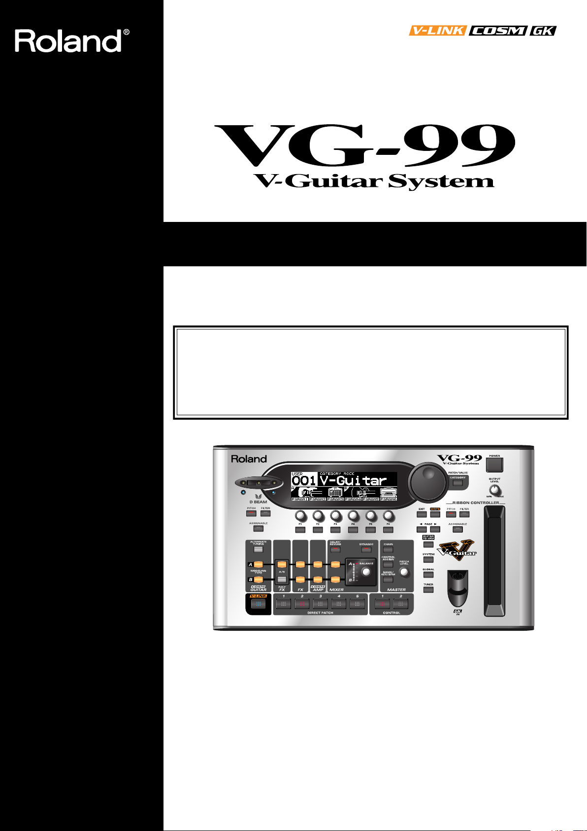
Thank you, and congratulations on your choice of the Roland VG-99.
202
Copyright © 2007 ROLAND CORPORATION
All rights reserved. No part of this publication may be reproduced in any form without the
written permission of ROLAND CORPORATION.
Roland Website http://www.roland.com/
201b
Before using this unit, carefully read the sections entitled: “USING THE UNIT SAFELY” (p.
2–3), and “IMPORTANT NOTES” (p. 4–5). These sections provide important information
concerning the proper operation of the unit. Additionally, in order to feel assured that you
have gained a good grasp of every feature provided by your new unit, Handbook and
Owner’s manual should be read in its entirety. The manual should be saved and kept on
hand as a convenient reference.
Owner’s Manual
2
USING THE UNIT SAFELY
001
• Before using this unit, make sure to read the
instructions below, and the Owner’s Manual.
...........................................................................................................
002c
• Do not open (or modify in any way) the unit or its
AC adaptor.
...........................................................................................................
003
• Do not attempt to repair the unit, or replace parts
within it (except when this manual provides
specific instructions directing you to do so). Refer
all servicing to your retailer, the nearest Roland
Service Center, or an authorized Roland
distributor, as listed on the “Information” page.
...........................................................................................................
004
• Never use or store the unit in places that are:
• Subject to temperature extremes (e.g., direct
sunlight in an enclosed vehicle, near a heating
duct, on top of heat-generating equipment); or
are
• Damp (e.g., baths, washrooms, on wet floors);
or are
• Humid; or are
• Exposed to rain; or are
• Dusty; or are
• Subject to high levels of vibration.
...........................................................................................................
005
• This unit should be used only with a rack-mount
adaptor (RAD-99) or stand (PDS-10) that is
recommended by Roland. (p. 98)
...........................................................................................................
006
• When using the unit with a stand (PDS-10) recom-
mended by Roland, the stand must be carefully
placed so it is level and sure to remain stable. If
not using a stand, you still need to make sure that
any location you choose for placing the unit
provides a level surface that will properly support
the unit, and keep it from wobbling.
...........................................................................................................
008c
• Be sure to use only the AC adaptor supplied with
the unit. Also, make sure the line voltage at the
installation matches the input voltage specified on
the AC adaptor’s body. Other AC adaptors may
use a different polarity, or be designed for a
different voltage, so their use could result in
damage, malfunction, or electric shock.
..........................................................................................................
008d
• Connect only the specified device (FC-300) to the
RRC2 IN connector (which provide a supply of
power).
..........................................................................................................
008e
• Use only the attached power-supply cord. Also,
the supplied power cord must not be used with
any other device.
..........................................................................................................
009
• Do not excessively twist or bend the power cord,
nor place heavy objects on it. Doing so can
damage the cord, producing severed elements
and short circuits. Damaged cords are fire and
shock hazards!
..........................................................................................................
010
• This unit, either alone or in combination with an
amplifier and headphones or speakers, may be
capable of producing sound levels that could
cause permanent hearing loss. Do not operate for
a long period of time at a high volume level, or at
a level that is uncomfortable. If you experience
any hearing loss or ringing in the ears, you should
immediately stop using the unit, and consult an
audiologist.
..........................................................................................................
011
• Do not allow any objects (e.g., flammable
material, coins, pins); or liquids of any kind
(water, soft drinks, etc.) to penetrate the unit.
..........................................................................................................
Used for instructions intended to alert
the user to the risk of injury or material
damage should the unit be used
improperly.
* Material damage refers to damage or
other adverse effects caused with
respect to the home and all its
furnishings, as well to domestic
animals or pets.
Used for instructions intended to alert
the user to the risk of death or severe
injury should the unit be used
improperly.
The ● symbol alerts the user to things that must be
carried out. The specific thing that must be done is
indicated by the design contained within the circle. In
the case of the symbol at left, it means that the power-
cord plug must be unplugged from the outlet.
The symbol alerts the user to important instructions
or warnings.The specific meaning of the symbol is
determined by the design contained within the
triangle. In the case of the symbol at left, it is used for
general cautions, warnings, or alerts to danger.
The symbol alerts the user to items that must never
be carried out (are forbidden). The specific thing that
must not be done is indicated by the design contained
within the circle. In the case of the symbol at left, it
means that the unit must never be disassembled.
3
012b
• Immediately turn the power off, remove the AC
adaptor from the outlet, and request servicing by
your retailer, the nearest Roland Service Center,
or an authorized Roland distributor, as listed on
the “Information” page when:
• The AC adaptor, the power-supply cord, or the plug
has been damaged; or
• If smoke or unusual odor occurs
• Objects have fallen into, or liquid has been spilled onto
the unit; or
• The unit has been exposed to rain (or otherwise has
become wet); or
• The unit does not appear to operate normally or
exhibits a marked change in performance.
..........................................................................................................
013
• In households with small children, an adult
should provide supervision until the child is
capable of following all the rules essential for the
safe operation of the unit.
..........................................................................................................
014
• Protect the unit from strong impact.
(Do not drop it!)
..........................................................................................................
015
• Do not force the unit’s power-supply cord to
share an outlet with an unreasonable number of
other devices. Be especially careful when using
extension cords—the total power used by all
devices you have connected to the extension
cord’s outlet must never exceed the power rating
(watts/amperes) for the extension cord. Excessive
loads can cause the insulation on the cord to heat
up and eventually melt through.
..........................................................................................................
016
• Before using the unit in a foreign country, consult
with your retailer, the nearest Roland Service
Center, or an authorized Roland distributor, as
listed on the “Information” page.
..........................................................................................................
023
• DO NOT play a CD-ROM disc on a conventional
audio CD player. The resulting sound may be of a
level that could cause permanent hearing loss.
Damage to speakers or other system components
may result.
..........................................................................................................
101b
• The unit and the AC adaptor should be located so
their location or position does not interfere with
their proper ventilation.
..........................................................................................................
101c
• This VG-99 for use only with Roland rack-mount
adaptor RAD-99 or Stand PDS-10. Use with other
rack-mount adaptors or stands are capable of
resulting in instability causing possible injury.
..........................................................................................................
102c
• Always grasp only the plug on the AC adaptor
cord when plugging into, or unplugging from, an
outlet or this unit.
..........................................................................................................
103b
• At regular intervals, you should unplug the AC
adaptor and clean it by using a dry cloth to wipe
all dust and other accumulations away from its
prongs. Also, disconnect the power plug from the
power outlet whenever the unit is to remain
unused for an extended period of time. Any
accumulation of dust between the power plug
and the power outlet can result in poor insulation
and lead to fire.
..........................................................................................................
104
• Try to prevent cords and cables from becoming
entangled. Also, all cords and cables should be
placed so they are out of the reach of children.
..........................................................................................................
106
• Never climb on top of, nor place heavy objects on
the unit.
..........................................................................................................
107c
• Never handle the AC adaptor or its plugs with
wet hands when plugging into, or unplugging
from, an outlet or this unit.
..........................................................................................................
108d: Selection
• If you need to move the instrument, take note of
the precautions listed below. It should be handled
carefully, all the while keeping it level. Make sure
to have a firm grip, to protect yourself from injury
and the instrument from damage.
1
• Check to make sure the screws or the attached knob
bolts securing the unit to the stand have not become
loose. Fasten them again securely whenever you notice
any loosening.
2
• Disconnect the power cord.
3
• Disconnect all cords coming from external devices.
..........................................................................................................
109b
• Before cleaning the unit, turn off the power and
unplug the AC adaptor from the outlet (p. 24).
..........................................................................................................
110b
• Whenever you suspect the possibility of lightning
in your area, disconnect the AC adaptor from the
outlet.
..........................................................................................................
118c
• Keep any screws you may remove and the
included screws in a safe place out of children’s
reach, so there is no chance of them being
swallowed accidentally.
..........................................................................................................

4
IMPORTANT NOTES
291a
In addition to the items listed under “USING THE UNIT
SAFELY” on page 2–3, please read and observe the
following:
Power Supply
301
• Do not connect this unit to same electrical outlet that is
being used by an electrical appliance that is controlled by
an inverter (such as a refrigerator, washing machine,
microwave oven, or air conditioner), or that contains a
motor. Depending on the way in which the electrical
appliance is used, power supply noise may cause this unit
to malfunction or may produce audible noise. If it is not
practical to use a separate electrical outlet, connect a
power supply noise filter between this unit and the
electrical outlet.
302
• The AC adaptor will begin to generate heat after long
hours of consecutive use. This is normal, and is not a
cause for concern.
307
• Before connecting this unit to other devices, turn off the
power to all units. This will help prevent malfunctions
and/or damage to speakers or other devices.
Placement
351
• Using the unit near power amplifiers (or other equipment
containing large power transformers) may induce hum.
To alleviate the problem, change the orientation of this
unit; or move it farther away from the source of inter-
ference.
352a
• This device may interfere with radio and television
reception. Do not use this device in the vicinity of such
receivers.
352b
• Noise may be produced if wireless communications
devices, such as cell phones, are operated in the vicinity of
this unit. Such noise could occur when receiving or initi-
ating a call, or while conversing. Should you experience
such problems, you should relocate such wireless devices
so they are at a greater distance from this unit, or switch
them off.
354a
• Do not expose the unit to direct sunlight, place it near
devices that radiate heat, leave it inside an enclosed
vehicle, or otherwise subject it to temperature extremes.
Excessive heat can deform or discolor the unit.
355b
• When moved from one location to another where the
temperature and/or humidity is very different, water
droplets (condensation) may form inside the unit. Damage
or malfunction may result if you attempt to use the unit in
this condition. Therefore, before using the unit, you must
allow it to stand for several hours, until the condensation
has completely evaporated.
360
• Depending on the material and temperature of the surface
on which you place the unit, its rubber feet may discolor
or mar the surface.
You can place a piece of felt or cloth under the rubber feet
to prevent this from happening. If you do so, please make
sure that the unit will not slip or move accidentally.
Maintenance
401a
• For everyday cleaning wipe the unit with a soft, dry cloth
or one that has been slightly dampened with water. To
remove stubborn dirt, use a cloth impregnated with a
mild, non-abrasive detergent. Afterwards, be sure to wipe
the unit thoroughly with a soft, dry cloth.
402
• Never use benzine, thinners, alcohol or solvents of any
kind, to avoid the possibility of discoloration and/or
deformation.
Repairs and Data
452
• Please be aware that all data contained in the unit’s
memory may be lost when the unit is sent for repairs.
Important data should always be backed up on a another
MIDI device (e.g., a sequencer), or written down on paper
(when possible). During repairs, due care is taken to avoid
the loss of data. However, in certain cases (such as when
circuitry related to memory itself is out of order), we
regret that it may not be possible to restore the data, and
Roland assumes no liability concerning such loss of data.
Additional Precautions
551
• Please be aware that the contents of memory can be
irretrievably lost as a result of a malfunction, or the
improper operation of the unit. To protect yourself against
the risk of loosing important data, we recommend that
you periodically save a backup copy of important data
you have stored in the unit’s memory in another MIDI
device (e.g., a sequencer).
552
• Unfortunately, it may be impossible to restore the contents
of data that was stored in another MIDI device (e.g., a
sequencer). once it has been lost. Roland Corporation
assumes no liability concerning such loss of data.
553
• Use a reasonable amount of care when using the unit’s
buttons, sliders, or other controls; and when using its jacks
and connectors. Rough handling can lead to malfunctions.
554
• Never strike or apply strong pressure to the display.
556
• When connecting / disconnecting all cables, grasp the
connector itself—never pull on the cable. This way you
will avoid causing shorts, or damage to the cable’s
internal elements.
558a
• To avoid disturbing your neighbors, try to keep the unit’s
volume at reasonable levels. You may prefer to use
headphones, so you do not need to be concerned about
those around you (especially when it is late at night).

5
IMPORTANT NOTES
559a
• When you need to transport the unit, package it in the box
(including padding) that it came in, if possible. Otherwise,
you will need to use equivalent packaging materials.
561
• Use only the specified expression pedal (Roland EV-5,
BOSS FV-500L/500H with a connection cable (stereo 1/4”
phone – stereo 1/4” phone); sold separately). By
connecting any other expression pedals, you risk causing
malfunction and/or damage to the unit.
562
• Some connection cables contain resistors. Do not use
cables that incorporate resistors for connecting to this unit.
The use of such cables can cause the sound level to be
extremely low, or impossible to hear. For information on
cable specifications, contact the manufacturer of the cable.
563
• Unauthorized duplication, reproduction, hiring, and
lending prohibited.
566a
• The usable range of D Beam controller will become
extremely small when used under strong direct sunlight.
Please be aware of this when using the D Beam controller
outside.
566b
• The sensitivity of the D Beam controller will change
depending on the amount of light in the vicinity of the
unit. If it does not function as you expect, adjust the sensi-
tivity as appropriate for the brightness of your location.
801
• Avoid touching or scratching the shiny underside
(encoded surface) of the disc. Damaged or dirty CD-ROM
discs may not be read properly. Keep your discs clean
using a commercially available CD cleaner.
962a + 962b
• In the interest of product improvement, the specifications,
appearance of this unit and/or contents of this package
are subject to change without prior notice.
986
• While under most conditions, a computer similar to the
above will permit normal operation of the VG-99, Roland
cannot guarantee compatibility solely on these factors.
This is due to numerous variables that may influence the
processing environment, such as differences in mother-
board design and the particular combination of other
devices involved.
Printing Conventions and
icons in This Manual
Text or numerals
enclosed in square
brackets [ ]
Indicate buttons.
[WRITE]
WRITE button
Indicates information that you
should be aware of when
using the VG-99.
Indicates supplementary
information about an
operation.
Indicates information about a
convenient operation.
(p.**)
Indicates a reference page.

6
Contents
IMPORTANT NOTES ...............................................................................4
Main Features........................................................................................11
Ultimate guitar modeling system provides unlimited possibilities in creating sounds.......11
Two complete sound creation systems ...................................................................................... 11
Equipped with D-Beam, ribbon, and other new realtime controllers................................... 11
Console style accommodates a variety of usage environments............................................. 11
Combine with the FC-300 to create the perfect live system.................................................... 11
Includes pitch/MIDI conversion function ................................................................................11
Features V-LINK function............................................................................................................ 11
Names of Things and What They Do...................................................12
Top Panel ................................................................................................................................................... 12
Rear Panel.................................................................................................................................................. 14
Chapter 1 Outputting Sounds..............................................................15
Installing the Divided Pickup................................................................................................................. 15
Before Connecting .................................................................................................................................... 15
Making the Connections.......................................................................................................................... 16
Turning On the Power ............................................................................................................................. 18
About the Play Screen .................................................................................................................. 19
About the Information in the Display (Basic Operation) ........................................................ 19
Adjusting the Volume ..................................................................................................................20
Setting the Device (Amp) Connected to MAIN OUT (Output Select) ..................................20
Inputting the Divided Pickup Settings (GK Settings) ......................................................................... 21
Tuning the Guitar (TUNER) ...................................................................................................................22
Switching Tones (Patch) .......................................................................................................................... 23
About the Patch Numbers ...........................................................................................................23
Switching with the PATCH/VALUE Dial ................................................................................ 24
Turning Off the Power............................................................................................................................. 24
Chapter 2 Creating Sounds..................................................................25
Setting the COSM GUITAR Tone........................................................................................................... 25
Setting the Alternate Tuning................................................................................................................... 26
Setting AB LINK............................................................................................................................ 26
Setting TUNING............................................................................................................................ 27
Setting BEND................................................................................................................................. 27
Setting 12-STRING........................................................................................................................ 28
Setting USER TUNING ................................................................................................................29
Setting DETUNE ........................................................................................................................... 29
Setting HARMONY ......................................................................................................................30
Setting the COSM AMP Tone ................................................................................................................. 30
Setting the Effects .....................................................................................................................................31
POLY FX (Poly Effect) ..................................................................................................................31
FX (Effects) .....................................................................................................................................31
Rearranging the Effect and Amp Connection Sequence (CHAIN)................................................... 32
Specifying the tempo and key of the song to be played ..................................................................... 32
Setting the Tempo .........................................................................................................................32
Setting the Key............................................................................................................................... 33
Mixing the Normal Pickup Sound ......................................................................................................... 33
Setting the Volume Balance ......................................................................................................... 33
Setting the Point at Which the COSM Guitar is Connected.................................................... 34
Mixing Two Tones (MIXER) ................................................................................................................... 35
Setting the Volume and Panning for Each Channel................................................................. 35
Setting the Mix Balance ................................................................................................................ 35
Setting the Delay and Reverb (DELAY/REVERB)................................................................... 35
Using Picking Dynamics to Control the Mix Between the Two Channels (DYNAMIC)......36

7
Contents
Setting the Overall Patch Volume Level (PATCH LEVEL) .................................................... 36
Adjusting the Overall Patch Tone (TOTAL EQ)....................................................................... 36
Setting the Output Signal and Level (OUTPUT)...................................................................... 37
Naming a Patch (PATCH NAME) ......................................................................................................... 37
Saving a Patch (WRITE) .......................................................................................................................... 38
Chapter 3 Creating Your Own Effect Types (CUSTOMIZE)...............39
Customizing the Preamp......................................................................................................................... 39
Customizing the Speaker ........................................................................................................................ 40
Customizing the Overdrive/Distortion................................................................................................ 40
Customizing Pedal Wah.......................................................................................................................... 41
Chapter 4 Global Device Settings (SYSTEM) .....................................42
Inputting the Divided Pickup Settings.................................................................................................. 42
Selecting the Settings .................................................................................................................... 42
Naming GK Settings (GK NAME).............................................................................................. 42
Selecting the Divided Pickup Type ............................................................................................43
Inputting the Guitar’s Scale......................................................................................................... 43
Matching the Divided Pickup and Normal Pickup Phase...................................................... 43
Setting the Direction for the Installed Divided Pickup ...........................................................43
Setting the DOWN/S1, UP/S2 Switch Arrangement.............................................................. 44
Setting the Gap Between the Pickup and the Bridge (PICKUP ´ BRIDGE) .......................... 44
Adjusting the Sensitivity for Each String .................................................................................. 45
Setting Whether or Not the Deviced Pickup Is Used (GK CONNCT) .................................. 45
Using Different Guitar Settings in Each Patch (SET MODE).................................................. 46
Determining the Function of the GK Volume Control and DOWN/S1, UP/S2 Switches
(GK FUNC) .................................................................................................................................... 46
Adjusting Overall Tone According to the Environment (GLOBAL/OUTPUT SELECT) ............. 46
Selecting the Settings .................................................................................................................... 46
Naming the Settings (GLOBAL NAME).................................................................................... 47
Setting the Types of Connected Devices (OUTPUT SELECT)................................................ 47
Adjusting the Overall Tone (GLOBAL EQ) .............................................................................. 48
Controlling the Overall Effect of the Noise Suppressor (Total NS)....................................... 48
Controlling the Overall Reverb Level (Total REVERB)........................................................... 49
Setting the Sounds Output from SUB OUT (SUB OUT LEVEL)............................................ 49
Setting the GK VOLUME Control and Switch and the Pedal Function
(SYSTEM CONTROL ASSIGN).............................................................................................................. 49
Having Values from an External Pedal, GK VOLUME Control,
or Other Controller Carried Over When Patches are Called Up (ASSIGN HOLD) ....................... 50
Limiting the Patches That Can Be Switched (PATCH EXTENT) ...................................................... 50
Adjusting the Screen’s Contrast ............................................................................................................. 51
Setting the Output Signal and Level (SYSTEM OUTPUT)................................................................. 51
Chapter 5 Using the VG-99 in Combination with an FC-300 .............52
Connecting with the RRC2 IN Connector............................................................................................. 52
Settings Related to the FC-300 ................................................................................................................ 52
Settings for Control of the FC-300 ..............................................................................................52
Setting the Operation When Patches Are Switched................................................................. 53
Activating the VG-99’s Tuner from the FC-300 (QUICK TUNER) ................................................... 53
Setting the FC-300 Amp Control ............................................................................................................ 54
Chapter 6 Using MIDI............................................................................55
About MIDI ............................................................................................................................................... 55
What You Can Do Using MIDI ................................................................................................... 55
Main Types of MIDI Messages Handled by the VG-99........................................................... 56
About the MIDI Implementation................................................................................................ 57
Exchanging MIDI Messages ........................................................................................................57

8
Contents
About MIDI Channels .................................................................................................................. 57
Bank Select and Program Change............................................................................................... 58
Setting the MIDI-Related Functions ......................................................................................................58
Syncing to the MIDI CLOCK from an External Device ...................................................................... 64
Playing an External Synthesizer Sound Module (GUITAR TO MIDI)............................................. 64
Setting the GUITAR TO MIDI Function (System Parameters)............................................... 64
Setting the GUITAR TO MIDI Function (Patch Parameters).................................................. 67
Chapter 7 Using the VG-99 Connected to a Computer Via USB.......71
Before Using the USB Connection.......................................................................................................... 71
Switching the Driver Mode ......................................................................................................... 72
Setting the USB Functions....................................................................................................................... 73
Setting the Digital Audio Signal Input and Output................................................................. 73
Setting the Direct Monitor ...........................................................................................................74
Recording the VG-99’s Output with a Computer................................................................................ 75
Using the VG-99 to Add Effects to Audio Playback from a Computer............................................ 75
Chapter 8 Other Functions...................................................................76
Changing the Tone in Real Time with the D Beam and Ribbon Controllers................................... 76
Adjusting the D Beam (CALIBRATION)................................................................................... 76
Disabling the D Beam (DISABLE) .............................................................................................. 77
Controlling Sounds by Hand Motion or the Guitar Neck (D Beam Controller).................. 77
Adjusting the Ribbon Controller (CALIBRATION)................................................................. 78
Controlling the Sounds with the Movement of Your Fingertip (Ribbon Controller) ......... 79
Holding Sounds for Extended Periods (FREEZE).................................................................... 79
Changing the Pitch as with a Tremolo Arm (T-ARM)............................................................. 80
Adding Nuance to the Sound (FILTER) .................................................................................... 81
Changing the Sounds with the Knobs as You Play (DIRECT EDIT) ................................................ 82
Using the Switches, Pedals, and MIDI to Control the Sounds (CONTROL ASSIGN)................... 82
One Touch Call Up of Favorite Patches (DIRECT PATCH)............................................................... 86
Setting DIRECT PATCH ..............................................................................................................86
Managing the Patches.............................................................................................................................. 87
Copying the Current Patch to a Different Patch (PATCH COPY)......................................... 87
Exchanging the Current Patch with a Different Patch (PATCH EXCHANGE) .................. 87
Initializing User Patches (PATCH INITIALIZE)...................................................................... 88
Copying Settings Between Channel A and Channel B (A/B COPY) ....................................88
Exchanging the Channel A and Channel B Settings (A/B EXCHANGE) ............................ 88
Partially Copying Parameters in a Different Patch (MODULE COPY) ................................89
Partially Initializing Patch Parameters (MODULE INITIALIZE).......................................... 89
Separating Patches into Groups (CATEGORY) ................................................................................... 90
Using CATEGORY to Call Up Patches ...................................................................................... 90
Setting Patch Categories............................................................................................................... 90
Naming User Categories (CATEGORY NAME) ...................................................................... 91
Storing Your Preferred Settings Individually (FAVORITE SETTINGS) .......................................... 91
What are Favorite Settings? ......................................................................................................... 91
Calling Up Favorite Settings........................................................................................................ 92
Changing Tone Settings ...............................................................................................................92
Saving Changed Tones................................................................................................................. 93
Naming Favorite Settings (FAVORITE NAME)....................................................................... 94
Searching for Patches That Use the Same Favorite Settings ................................................... 94
Activating the Virtual Expression Pedal at the Start of Operations (Internal Pedal System) ....... 95
Internal Pedal................................................................................................................................. 95
Wave Pedal .................................................................................................................................... 95
Controlling Video Images with Your Guitar (V-LINK)...................................................................... 96
What is V-LINK? ........................................................................................................................... 96
Connecting the V-LINK Device ..................................................................................................96
Switching V-LINK On and Off.................................................................................................... 96

9
Contents
Setting V-LINK .............................................................................................................................. 97
Using the VG-99 on a Stand.................................................................................................................... 98
Using the VG-99 Mounted in a Rack ..................................................................................................... 99
Restoring the VG-99 to its Original Factory Condition (FACTORY RESET)................................. 100
Chapter 9 Parameters Guide..............................................................101
COSM GUITAR ......................................................................................................................................101
Modeling Type List..................................................................................................................... 101
ALTERNATE TUNING.............................................................................................................. 116
POLY FX (Poly Effect)............................................................................................................................ 118
FX (Effects)............................................................................................................................................... 120
Using the HOLD (Hold Delay) .................................................................................................125
PHASER........................................................................................................................................ 127
FLANGER ....................................................................................................................................128
TREML (Tremolo) ....................................................................................................................... 128
PAN............................................................................................................................................... 128
T.WAH (Touch Wah).................................................................................................................. 129
AUTO WAH ................................................................................................................................129
OCTAVE....................................................................................................................................... 129
PITCH SHIFT (Pitch Shifter) ..................................................................................................... 130
HARMONIST ..............................................................................................................................130
Creating Harmonist Scales (User Scale)................................................................................... 131
PEDAL BEND.............................................................................................................................. 132
2x2 CHORUS ...............................................................................................................................132
ROTARY....................................................................................................................................... 133
UNI-V............................................................................................................................................ 133
VIB (Vibrato)................................................................................................................................ 133
SLICER.......................................................................................................................................... 134
HUMANIZER.............................................................................................................................. 134
SLOW GEAR................................................................................................................................ 135
DEFRET ........................................................................................................................................135
FEEDBACKER............................................................................................................................. 135
RING MOD (Ring Modulator) .................................................................................................. 136
ANTI FB (Anti-feedback)........................................................................................................... 136
ADV.COMP (Advanced Compressor)..................................................................................... 136
LIMITR (Limiter)......................................................................................................................... 137
SUB EQ (Sub Equalizer) ............................................................................................................. 137
SUB DELAY (Sub Delay) ........................................................................................................... 138
COSM AMP............................................................................................................................................. 140
MIXER ...................................................................................................................................................... 146
MIXER A, B (MIXER CHANNEL A, B) ................................................................................... 146
PATCH LEVEL............................................................................................................................ 146
TOTAL EQ ................................................................................................................................... 146
OUTPUT....................................................................................................................................... 147
DELAY.......................................................................................................................................... 148
MASTER .................................................................................................................................................. 150
GK VOL (GK Volume) ............................................................................................................... 150
GK S1, S2 (DOWN/S1, UP/S2 Switch).................................................................................... 150
PANEL CTL1/CTL2 (Control Button 1/2) .............................................................................151
D BEAM........................................................................................................................................ 151
RIBBON ........................................................................................................................................153
EXP PEDAL (Expression Pedal)................................................................................................ 154
CTL3, CTL4 (Control3, Control4) .............................................................................................154
FC-300 CONTROL ...................................................................................................................... 155
ASSIGN 1–16................................................................................................................................ 155
DIRECT EDIT F1–F6................................................................................................................... 156
GUITAR TO MIDI .................................................................................................................................. 164

10
Contents
SYSTEM ................................................................................................................................................... 166
Parameters That Can Be Assigned to Separate Controllers.................................................. 168
V-LINK PATCH .......................................................................................................................... 174
V-LINK SYSTEM......................................................................................................................... 176
GLOBAL ..................................................................................................................................................177
TUNER..................................................................................................................................................... 178
Chapter 10 Appendices ......................................................................179
MIDI Implementation Chart................................................................................................................. 179
Signal Flow .............................................................................................................................................. 183
Specifications........................................................................................................................................... 184
VG-99: V-Guitar System............................................................................................................. 184
VG-99 Software System Requirements ............................................................................................... 185
For Windows ............................................................................................................................... 185
For Mac OS................................................................................................................................... 185
Error Messages........................................................................................................................................ 186
Troubleshooting...................................................................................................................................... 186
Problems with Sounds................................................................................................................ 186
Other Problems............................................................................................................................ 188
Index.....................................................................................................189

11
Main Features
The VG-99 is the culmination of Roland’s COSM technology based
guitar modeling systems. Featuring advanced software supported by
the very latest custom DSP chips, the instrument also offers a large-
sized high-contrast LCD, top-quality AD/DA converters, balanced
XLR output connectors, digital output connectors, USB connector,
and other features that all add up to a truly pro-spec system.
The VG-99 features two separate guitar and COSM amp systems.
You can use two different types of modeled guitars simultaneously
and create different amp sounds to use with each guitar. What’s
more, the VG-99 comes equipped with two effects systems featuring
a huge selection of BOSS effects, including COSM effects. This all
enables you to achieve the perfect processing for each individual
guitar.
The VG-99 now enables new and heretofore unimaginable forms of
musical expression, including new ways of using the guitar’s neck
and your hands. Of course, you can still connect expression pedals
and control switches as well, just as with previous V-Guitar systems.
The VG-99 can be set up in a number of different ways to suit the
needs of the user—as a desktop unit for recording or when using
computer input, attached to its stand (optional) and set up right by
the performer, or placed in a rack with the (optional) rack mount
adaptor.
Connecting a Roland FC-300 MIDI Foot Controller (optional) to the
VG-99 allows you to switch tones and carry out other tasks using the
FC-300’s multiple foot pedals for easy hands-free operation. These
units also feature an RRC2 connector, allowing you to connect the
VG-99 and FC-300 with a single cable. This RRC2 function enables
two-way communications between the devices, while further acting
as a power supply to the FC-300, thus reducing the number of cables
used to connect the devices.
The VG-99 can convert and output guitar performance data as MIDI
information, allowing you to connect a synthesizer sound module or
similar device and use the setup as a guitar synthesizer.
This function enables you to use performance data and pedal
operations in controlling video.
Ultimate guitar modeling system
provides unlimited possibilities
in creating sounds
Two complete sound creation
systems
Equipped with D-Beam, ribbon,
and other new realtime controllers
Console style accommodates a
variety of usage environments
About COSM
(Composite Object Sound Modeling)
Composite Object Sound Modeling—or “COSM” for short—is
BOSS/Roland’s innovative and powerful technology that’s
used to digitally recreate the sound of classic musical
instruments and effects. COSM analyzes the many factors that
make up the original sound—including its electrical and
physical characteristics—and creates a digital model that
accurately reproduces the original.
Combine with the FC-300 to
create the perfect live system
Includes pitch/MIDI conversion
function
Features V-LINK function
V-LINK
V-LINK is a function that allows music and images to be
performed together. By using MIDI to connect two or more V-
LINK compatible devices, you can easily enjoy a wide range of
visual effects that are linked to the expressive elements of a
music performance.

12
Names of Things and What They Do
fig.00-020
1.
D BEAM
Switches the D Beam on and off. You can add a variety of
effects to your sounds by moving your hand or the guitar neck
within the range of the beam. (p. 76)
• PITCH Button
In addition to changing the pitch of the guitar, this can be
used for the Freeze function, which continuously holds
the guitar’s tone.
• FILTER Button
This changes the guitar’s tone.
• ASSIGNABLE Button
Use this to assign different parameters and functions to
the D-Beam and change the tone in real time.
2.
LCD
Various information regarding the VG-99 is indicated here.
3.
PATCH/VALUE Dial
Used to switch patches and change settings values.
4.
CATEGORY Button
Used to select and change categories.
5.
FUNCTION Knob
Changes the value of the setting for the parameter indicated in
the LCD.
6.
FUNCTION Buttons
Used to select the parameters indicated in the LCD.
7.
ALTERNATE TUNING Button
Sets the Alternate Tuning function. (p. 26)
8.
MODELING TYPE Buttons
These set the COSM guitar type and tone. (p. 25)
9.
POLY FX (Poly Effects) Buttons
These set the poly effects. (p. 31)
10.
FX (Effects) Buttons
These set the effects. (p. 31)
11.
COSM AMP Buttons
Used to make settings for the COSM amp. (p. 30)
12.
MIXER Buttons
Used to make settings for the mixer. (p. 35)
13.
DELAY/REVERB Button
Used to make settings for the mixer section’s delay and
reverb. (p. 35)
14.
DYNAMIC Button
Used for setting the dynamics. (p. 36)
Top Panel
3
4
30
7
8 9
10 11 12
13 14
15
16
17
18
19
20 21 22
27
29
23 24
28
25
26
33
31
32
1 2
5
6

13
Names of Things and What They Do
15.
BALANCE Knob
Sets the mix balance. (p. 35)
16.
CHAIN Button
Used to make settings for the effect and COSM guitar/COSM
amp connection sequence. (p. 34)
17.
CONTROL ASSIGN Button
This sets the functions assigned to pedals and switches. (p. 82)
18.
NAME/KEY/BPM Button
Used to specify patch names and the tempo and key for songs
to be played. (p. 32)
19.
PATCH LEVEL Knob
Adjusts the volume of a patch.
20.
V-LINK Button
This switches the V-LINK function on and off. (p. 96)
21.
DIRECT PATCH Buttons
Use these to directly call up the patches you have assigned to
them. (p. 86)
22.
CONTROL Buttons
You can assign and control a variety of different functions
with these buttons. (p. 82)
23.
EXIT Button
Used to return previous screens and to undo operations.
24.
WRITE Button
Use for storing settings in patches and executing operations.
(p. 38) (p. 87)
25.
PAGE Buttons
This switches the screens displayed in the LCD.
26.
GUITAR TO MIDI Button
This sets the GUITAR TO MIDI function (the function that
converts what is played on the guitar into MIDI signals). (p.
64)
27.
SYSTEM Button
Used for making settings related to the VG-99’s operating
environment. (p. 42)
28.
GLOBAL Button
This sets the GLOBAL function (which affects the tone of all
patches). (p. 46)
29.
TUNER Button
This turns the tuning function on. (p. 22)
30.
RIBBON CONTROLLER
This allows you to change the tone by sliding your finger
along the ribbon. (p. 77)
You can switch a variety of effects on and off directly with the
three buttons.
• PITCH Button
Changes the guitar’s pitch.
• FILTER Button
Alters the brightness of the sound.
• ASSIGNABLE Button
Use this to assign different parameters and functions to
the ribbon controller and change the tone in real time. (p.
82)
31.
GK IN Connector
Connect the GK cable here.
32.
POWER Switch
Switches the power on and off. (p. 18) (p. 24)
33.
OUTPUT LEVEL Knob
This adjusts the volume level for the MAIN OUT jacks and
headphone jack.

14
Names of Things and What They Do
fig.00-030
1.
Security Slot ( )
988
Connect a commercially available anti-theft security cable
here.
http://www.kensington.com/
2.
GUITAR INPUT Jack
Use this jack when directly inputting a normal guitar.
3.
GUITAR OUTPUT Jack
This outputs sounds from normal guitars connected to a GK-3
and unaltered signals from the GUITAR INPUT jack.
4.
SUB OUT Connectors L, R
These balanced output jacks use XLR type connectors.
* The SUB OUT L and R connectors are unaffected by the OUTPUT
LEVEL knob settings; output is constant at a fixed output level (+4
dBu).
5.
GND LIFT Switch
You can disconnect the SUB OUT connectors’ No. 1 pin from
the VG-99’s ground.
Switch this to LIFT if a ground loop or similar problem is
causing output of hum or noise. Normally, this is set to GND.
6.
MAIN OUT Jacks L/MONO, R
These are unbalanced phone jack outputs. Use these to
connect to amps, mixers, and similar equipment.
7.
PHONES Jack
Connect headphones here.
8.
DIGITAL OUT Connector
Digital audio signals are output here. (p. 37) (p. 147)
9.
EXP PEDAL (EXPRESSION PEDAL) Jack
Connect an optional expression pedal (such as a Roland EV-5)
here. (p. 16)
* The VG-99 is set at the factory so that the pedal is automatically
enabled to function as a foot volume.
10.
CTL3,4 (CONTROL 3,4) Jack
An optional footswitch (such as an FS-6) can be connected
here. (p. 16)
* The patch up/down function is assigned to this jack at the factory.
11.
USB Connector
Use a USB cable to connect a computer to this connector and
enable exchange of data between the VG-99 and the computer.
(p. 71)
12.
RRC2 IN Connector
Accepts connection of an FC-300 (optional).
This connector supplies power to the FC-300 and provides for
two-way communications with it. (p. 52)
* The RRC2 IN connector is for use exclusively with the FC-300. It
cannot be used with other devices.
13.
MIDI OUT, IN Connector
Connect an external MIDI device here to transmit and receive
MIDI messages to and from the device. (p. 58)
14.
DC IN (AC Adaptor) Jack
Connect the included AC adaptor here.
To prevent damaging the VG-99, please be sure not to use any
AC adaptor other than the one included with the VG-99.
15.
Cord Hook
Fasten the AC adaptor cord using this hook to prevent the
cord from being disconnected accidentally. (p. 17)
* Disconnecting the AC adaptor while the VG-99 is in use may result
in corruption of important data.
Rear Panel
3
4
7 8 9
10 11 12 13
14
15
1
2
5
6
15
Chapter 1
Chapter 1 Outputting Sounds
First install the GK-3 divided pickup (optional) on the guitar to be
used. For installation instructions, refer to the GK-3 Owner’s
Manual.
The GK-3 cannot be used with the following guitars (the
pickup will not function properly even when installed).
• 12-string guitars, pedal steel guitars, and guitars with other
than six strings
• Nylon-stringed or gut-stringed guitars and guitars using any
non-steel strings
• Bass guitars
• Other guitars whose construction does not provide adequate
space to properly attach the GK-3
About the GK-3’s GK Volume Control
With the VG-99, you can assign various different functions to the
GK-3’s GK volume control. p. 82
You may not be able to control the VG-99’s volume level with the GK
volume control another parameter is assigned to the GK volume
control.
About the GK-3’s Select Switches
As the VG-99 allows you to set the balance between the COSM guitar
and the normal guitar volume in each individual patch, we
recommend that MIX be the basic function used for the select switch.
Also note that if a parameter other than volume is assigned as the
GK volume control function, the GK-3’s select switch will stop
functioning normally.
To perform with the VG-99, first set up the following devices.
• A guitar on which the GK-3 has been installed or equipped with
internal GK function
• Guitar amp/speaker or headphones
Performing can be made even more convenient using the following
devices:
• MIDI foot controller (Roland FC-300; optional)
• Expression pedal (Roland EV-5 or BOSS FV-500L/500H with a
connection cable (stereo 1/4” phone – stereo 1/4” phone);
optional)
• Pedal switch (BOSS FS-5U or FS-6; optional)
Installing the Divided Pickup
Before Connecting

16
Chapter 1 Outputting Sounds
Top Panel
Rear Panel
Making the Connections
Guitar with GK-3 / GK-2A /
other GK-Compatible guitar
GK cable
Guitar Amp
(for Normal Guitar)
Stereo
Headphones
Normal Guitar
Digital
Recorder etc.
MIDI Foot Controller
FC-300
Mixer etc.
Footswitch
(BOSS FS-6 etc.)
EXP Pedal
(EV-5 etc.)
Computer
RRC2 cable
MIDI Sequencer etc.
MIDI IN MIDI OUT
AC Adaptor PSB-1U
V-LINK
Compatible Device
(EDIROL MD-P1 etc.)
Computer
MIDI IN
MIDI IN
Synthesizer
(external sound module) etc.
17
Chapter 1 Outputting Sounds
Chapter 1
921
• To prevent malfunction and/or damage to speakers or
other devices, always turn down the volume, and turn off
the power on all devices before making any connections.
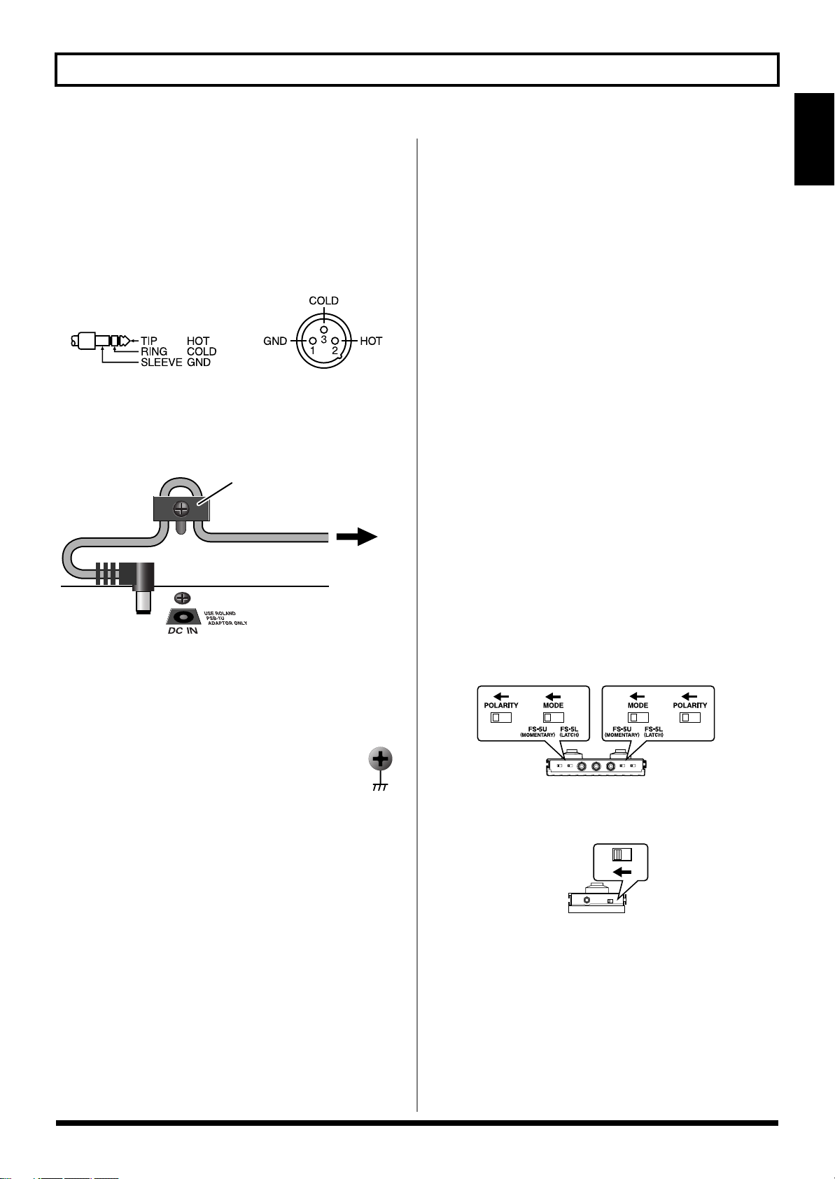
922
• This instrument is equipped with balanced type jacks
(TRS=CTL3,4; XLR=SUB OUT). Wiring diagrams for these
jacks are shown below. Make connections after first
checking the wiring diagrams of other equipment you
intend to connect.
fig.XLR/TRSJack.eps
924
• To prevent the inadvertent disruption of power to your
unit (should the plug be pulled out accidentally), and to
avoid applying undue stress to the AC adaptor jack,
anchor the power cord using the cord hook, as shown in
the illustration.
fig.CordHook.e.eps
925
* Use only the specified expression pedal (Roland EV-5,
BOSS FS-500L/500H with a connection cable (stereo 1/4”
phone – stereo 1/4” phone); sold separately). By
connecting any other expression pedals, you risk causing
malfunction and/or damage to the unit.
927
* Depending on the circumstances of a particular
setup, you may experience a discomforting
sensation, or perceive that the surface feels gritty
to the touch when you touch this device, micro-
phones connected to it, or the metal portions of
other objects, such as guitars. This is due to an
infinitesimal electrical charge, which is absolutely
harmless. However, if you are concerned about
this, connect the ground terminal (see figure) with
an external ground. When the unit is grounded, a
slight hum may occur, depending on the partic-
ulars of your installation. If you are unsure of the
connection method, contact the nearest Roland
Service Center, or an authorized Roland
distributor, as listed on the “Information” page.
Unsuitable places for connection
• Water pipes (may result in shock or electrocution)
• Gas pipes (may result in fire or explosion)
• Telephone-line ground or lightning rod (may be
dangerous in the event of lightning)
926a
• When connection cables with resistors are used, the
volume level of equipment connected to the GUITAR
INPUT may be low. If this happens, use connection cables
that do not contain resistors.
* Never connect anything other than the FC-300’s RRC2 OUT
connector to the VG-99’s RRC2 IN connector. Connecting to a LAN
or other devices that use modular jacks of the same size and shape
(RJ45) may result in damage to the VG-99 and/or the connected
device.
* If using a commercially available ethernet cable as the RRC2
connecting cable, be sure that the cable meets the following
specifications:
• Category 5 (Cat5) or above
• Maximum length of 15 meters
• Cable designed for straight-through connections
* Crossover cables cannot be used.
* Do not subject the ethernet cable to stress or physical shock.
* Carefully connect the RRC2 cable all the way in–until it is firmly
connected to the RRC2 IN connector.
* When outputting in mono, connect a cable only to the MAIN OUT
L/MONO jack.
* You cannot use COSM GUITAR or POLY FX with signals input
via GUITAR IN. The GT-PRO’s internal FX, COSM AMP,
MIXER, and other settings can be used fully in two channels.
* When connecting an expression pedal to the EXP PEDAL jack, use
the pedal with the minimum level at the MIN position.
* When connecting an FS-6 footswitch (optional) to the CTL3/4 jack,
set the MODE switch and POLARITY switch as shown below.
fig.01-010
* When connecting an FS-5U footswitch (optional) to the CTL3/4
jack, set the POLARITY switch as shown below.
fig.01-020
=CTL3
=CTL4
Cord Hook
The cord of
the supplied AC Adaptor
To the Power Outlet
BOSS FS-6
BA
BOSS FS-5U

18
Chapter 1 Outputting Sounds
* You can connect two FS-5Us using the special Roland PCS-31
connection cable (optional).
* When an FS-6 is connected to the CTL3,4 jack with an optional
connection cable (stereo 1/4” phone
–
stereo 1/4” phone), pedal
switch B operates according to the CONTROL 3 settings, and pedal
switch A operates according to the CONTROL 4 settings.
fig.01-030
941
Once the connections have been completed p. 16, turn on power to
your various devices in the order specified. By turning on devices in
the wrong order, you risk causing malfunction and/or damage to
speakers and other devices.
942
• This unit is equipped with a protection circuit. A brief
interval (a few seconds) after power up is required before
the unit will operate normally.
943
• Always make sure to have the volume level turned down
before switching on power. Even with the volume all the
way down, you may still hear some sound when the
power is switched on, but this is normal, and does not
indicate a malfunction.
* Turning on devices in the wrong sequence may result in
malfunction and/or damage to speakers and other devices.
1.
Switch on the POWER switch on the VG-99’s
top panel.
The display changes as described below, and after several
seconds the VG-99 is ready for normal performance.
This screen is called the “Play screen.”
fig.01-060d
Unless special note is made otherwise, the operations
described in this manual are carried out with the Play screen
displayed.
* When the power to the VG-99 is turned on, the patch selected at the
time the power was last turned off is called up.
985
• The explanations in this manual include illustrations that
depict what should typically be shown by the display.
Note, however, that your unit may incorporate a newer,
enhanced version of the system (e.g., includes newer
sounds), so what you actually see in the display may not
always match what appears in the manual.
2.
Turn on the power to the guitar amp or mixer.
* Raise amp volume levels only after turning on the power to all the
devices.
PCS-31 cable
To CTL3,4 jack To CTL3,4 jack To CTL3,4 jack
White Red White Red
BOSS
FS-5U
(CTL3)
BOSS
FS-5U
(CTL4)
(CTL3) (CTL4)
(CTL4) (CTL3)
• When using the VG-99 with an expression pedal connected
to the EXP PEDAL jack, make the settings described on p.
154.
• When using the VG-99 with a footswitch connected to the
CTL3/4 jack, make the settings described on p. 154.
Turning On the Power
19
Chapter 1 Outputting Sounds
Chapter 1
The VG-99 has a variety of Play screen variations, each providing
different information about the current state of the VG-99.
You can switch the information shown in the Play screen by pressing
PAGE [ ] [ ].
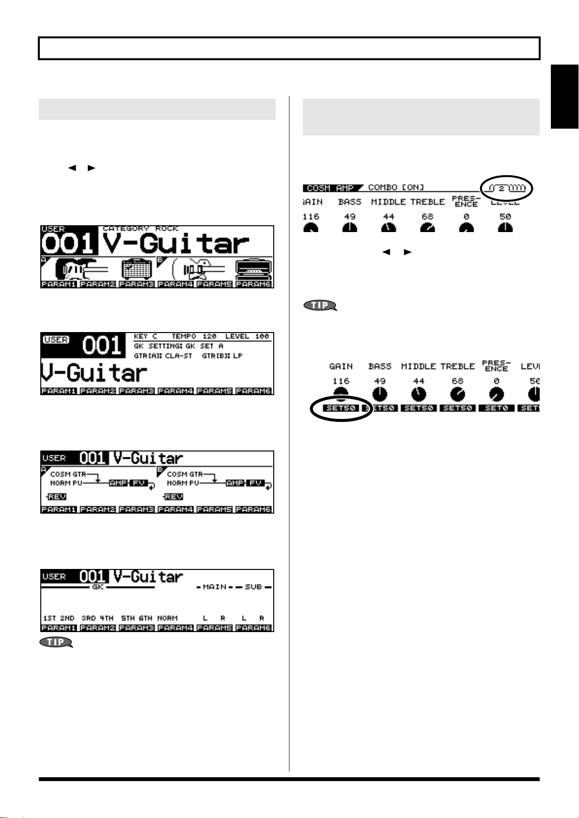
Screen 1:
The first nine characters of the patch name are displayed in large
type; also shown are icons for the guitars and amps in both channels.
fig.01-060d
Screen 2:
All sixteen characters of the patch name are displayed.
Screen 3:
The effects used, as well as their connection sequence (CHAIN) in
both channels are indicated.
Screen 4:
The screen shows level meters for the GK IN strings 1–6, normal
pickup, MAIN OUT, and SUB OUT levels.
By assigning parameters to the F1–F6 knobs, as
described in
“Changing the Sounds with the Knobs
as You Play (DIRECT EDIT)”
(p. 82), you can use them
to control values while in the Play screen. Additionally,
you can display a popup for the assigned parameters
and their values by pressing the [F1]–[F6] buttons.
Some screens may contain parameters spanning multiple pages. The
page number is indicated at the upper right of the screen.
1.
Use PAGE [ ] [ ] to switch pages.
2.
Use [F1]–[F6] or the F1–F6 knobs to change
the values.
Pressing a FUNCTION button while SET** appears in
the lower part of the screen sets the corresponding
function to the indicated value of **.
About the Play Screen
About the Information in the
Display (Basic Operation)

20
Chapter 1 Outputting Sounds
Turn the OUTPUT LEVEL knob to set the volume to a suitable level.
fig.01-070
* The output from the SUB OUT connector (XLR type) remains
constant, regardless of the OUTPUT LEVEL knob setting.
* You can adjust the volume level by assigning this function to the
expression pedal or GK-3 GK volume control. For details, see
“Using the Switches, Pedals, and MIDI to Control the
Sounds (CONTROL ASSIGN)”
(p. 82).
Use this procedure to set the type of device connected to the MAIN
OUT jacks.
fig.01-071
1.
Press [GLOBAL].
The Global screen is displayed.
fig.01-072d
2.
Press PAGE [ ] to go to Page 1.
3.
Press [F4] (SELECT) or turn the F4 knob to set
the type of device to be connected to the MAIN
OUT jacks.
4.
Press [EXIT] to return to the Play screen.
Adjusting the Volume
Setting the Device (Amp)
Connected to MAIN OUT (Output
Select)
Value
Explanation
JC-120
Use this setting when connecting to Roland’s
JC-120 guitar amp.
SMALL AMP
Use this setting when connecting to a small
guitar amp.
COMBO AMP
Use this setting when connecting to the guitar in-
put of a combo amp other than the JC-120 guitar
amp (where the amp and speaker or speakers are
combined in a single unit).
* Depending on your guitar amp, you may be
able to obtain good results with the JC-120
setting.
STACK AMP
Use this setting when connecting to the guitar
input of a stack-type guitar amp (where the
amp and speaker or speakers are separated).
JC-120 Return
Use this setting when connecting to the RE-
TURN of a JC-120.
COMBO Return
Use this setting when connecting to the RE-
TURN of a combo amp.
STACK Return
Use this setting when connecting to the RE-
TURN of a stack amp or the input of a rack
mounted power amp.
Set to STACK Return also when using a guitar
power amp and speaker cabinet combination.
LINE/PHONES
Use this setting when using headphones or
when connecting to a multi-track recorder for
recording.
3
3
4
1
2
21
Chapter 1 Outputting Sounds
Chapter 1
The VG-99’s sound characteristics vary greatly depending on how
the divided pickup is installed. To ensure consistent conditions for
optimal sound production, be sure to make the settings affecting the
divided pickup (the GK settings). With these settings appropriately
made, the VG-99 can then operate under optimal conditions.
* For information on parameters not described in this chapter, refer to
“GK SETTING”
(p. 166).
When using more than one guitar with the VG-99, you
can save the settings for each guitar separately.
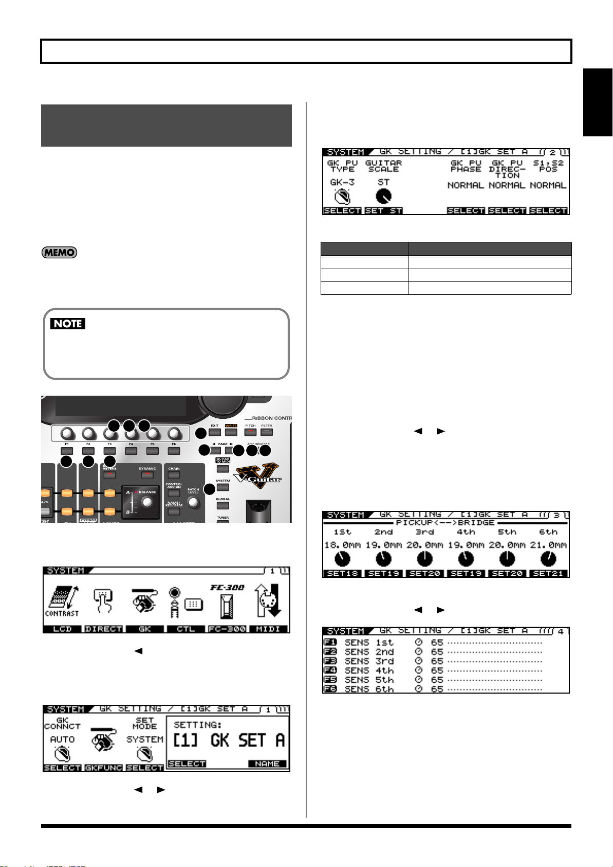
fig.01-100
1.
Press [SYSTEM].
The System screen is displayed
2.
Press PAGE [ ] to go to Page 1.
3.
Press [F3] (GK).
The GK Settings screen is displayed.
fig.01-060d
4.
Press PAGE [ ] [ ] to go to Page 2.
5.
Select the divided pickup type.
Use the F1 knob to set the type of divided pickup installed in
the guitar you are using.
fig.01-060d
* Piezo pickups are a type of pickup that are installed at the guitar’s
bridge and use piezoelectric elements to determine the string
vibrations.
6.
Set the scale length.
Use the F3 knob to set the scale length (the distance from the
bridge to the nut) of the guitar you are using. Select the closest
value within the 620-660 mm range. 648 mm is corresponds to
the ST setting, 628 mm to the LP setting.
7.
Press PAGE [ ] [ ] to go to Page 3.
8.
Input the gap between the pickup and the
bridge.
Set the clearance from the center of the divided pickup to the
bridge’s saddle.
* This setting is not required when piezo pickups are used.
9.
Press PAGE [ ] [ ] to go to Page 4.
fig.01-060d
10.
Rotate the F1–F6 knobs to adjust the divided
pickup sensitivity for each string.
First play the sixth string with the maximum force to be used
during actual performance, and as you play the string, set the
sensitivity with the F1 knob until the meter registers at a point
just before it crosses beyond the maximum level.
Set the sensitivity for the fifth through first strings in the same
manner.
Inputting the Divided Pickup
Settings (GK Settings)
The GK settings are extremely important to getting
good tones from the VG-99. Be sure to input the
settings correctly.
3
4
1
2
5 6
7 9
12
10 11
8
Settings
Explanation
GK-3
Specifies the GK-3.
GK-2A Specifies the GK-2A.
PIEZO Specifies a piezo pickup.
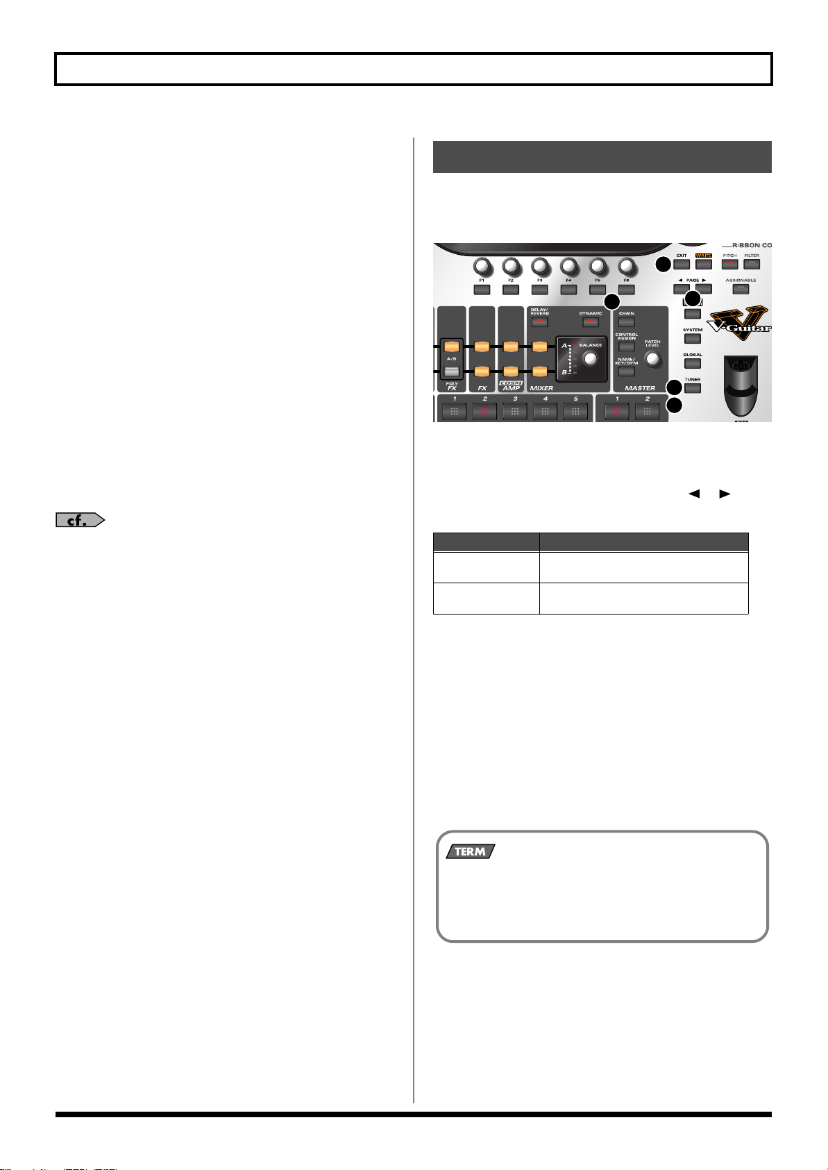
22
Chapter 1 Outputting Sounds
* If the level meter registers in excess of the maximum level, it means
the level is set too high. Lower the sensitivity setting.
* Depending on the guitar you are using, the level meter may move to
the maximum level even when the sensitivity is set to the minimum
setting. If this occurs, adjust the clearance separating the divided
pickup and the strings so the distance is slightly greater than
specified.
11.
Check the volume balance of the six strings.
Play the sixth through first strings with the normal amount of
force; if any string sounds particularly loud, lower the
sensitivity setting for that string, and keep adjusting until the
differences in the strings’ volume levels are minimal.
12.
Press [EXIT] several times to return to the Play
screen.
* Making these settings is necessary whenever you install the divided
pickup on a new or different guitar and when the divided pickup
height is changed. Once the settings are completed properly, they are
saved when the power is turned off. Afterwards, you need not make
the settings each time you play the instrument.
For more information on other parameters in the GK
Settings, refer to
“GK SETTING”
(p. 166).
Tune the guitar using the VG-99’s tuner function.
* To get the best tone quality from the VG-99, make sure the tuning is
accurate.
fig.01-190
1.
Press [TUNER].
The tuner function is switched on.
2.
Set the following with the PAGE [ ] [ ]
buttons.
3.
Press the function button ([F5] [F6])
corresponding to the function you want to set,
then rotate the knobs to select the value for
the setting.
If you do not want to change these settings, proceed to Step 4.
• [F5] (PITCH: 435 Hz–445 Hz)
This sets the reference pitch.
* With the factory settings, this is set to 440 Hz.
* This reference pitch is referenced by effects controlled by the KEY
parameter.
Tuning the Guitar (TUNER)
TUNER
Explanation
MULTI MODE
You can play and tune six strings simulta-
neously.
SINGLE MODE
You can play one individual string to
tune that string.
3
1
2
7
7
What is the Reference Pitch?
This is the frequency at A4 (the note played with the A key at
the middle of the piano keyboard) played by the instrument
(e.g. piano) used as the reference for tuning for performances.

23
Chapter 1 Outputting Sounds
Chapter 1
• [F6] (MUTE OFF, MUTE ON)
This setting determines whether sounds from the output
jacks are output or not while tuning is in progress.
4.
Play a single note, open, on the string being
tuned.
5.
Tune the string until the name of the string is
shown in the display.
When you choose the MULTI MODE
fig.01-060d
When you choose the SINGLE MODE
fig.01-060d
6.
Keep checking the screen, tuning until the
center indicator lights up.
Repeat Steps 3-5 to tune all the strings.
* When tuning a guitar equipped with a tremolo arm, you may find
that when one string is in tune, other strings may not be. If this
occurs, first tune the string until its name is indicated in the display,
then continue to fine tune each string a number times until the
tuning is correct.
7.
When you have finished tuning, press
[TUNER] or [EXIT].
This completes the preparations for playing
the instrument. Now try playing some sounds.
Patch numbers (bank numbers) and patch names are indicated in the
Play screen as shown below.
fig.01-060d
Patches are categorized into User patches and Preset patches.
User Patches
These include 200 preprogrammed patches. You can freely change
the tones and save the your changes.
Preset Patches
Included here are 200 preprogrammed patches. Although you can
make changes to these tones, you cannot save these changes in a
Preset Patch. If you want to save a changed tone, save it as a User
patch.
TUNER
Explanation
MUTE OFF
Sounds are output during tuning.
MUTE ON
Sounds are not output during tuning.
* With the factory settings, this is set to
MUTE ON.
Switching Tones (Patch)
About the Patch Numbers
What is a patch?
The VG-99 can store 400 configurations of tone-related
settings, including the COSM guitar, COSM amp, and
effects. Each one of these is called a patch.
Each time you switch a patch, you can instantly change to
a different tone.
Patch Number
Patch Name
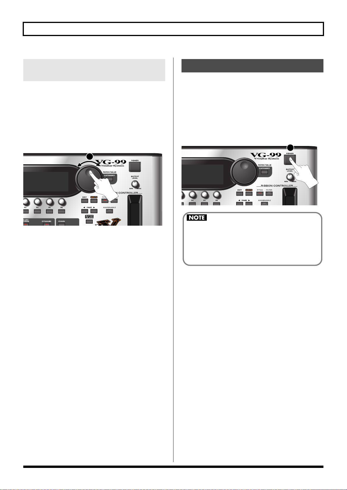
24
Chapter 1 Outputting Sounds
You can switch patches consecutively with the PATCH/VALUE
Dial.
1.
Confirm that the Play screen is displayed.
If a screen other than the Play screen is shown, press [EXIT]
several times until the Play screen appears.
2.
Rotate the PATCH/VALUE dial to switch the
patches.
fig.01-190
Turn the dial to the right (clockwise) to switch to the next
patch number, or to the left (counterclockwise) to switch to the
previous patch number.
1.
Confirm the following before turning off the
power.
• Are the volume levels for the VG-99 and connected amp and
other devices turned down completely?
2.
Turn off the power to the guitar amp (power
amp).
3.
Press [POWER] to turn off the VG-99’s power.
fig.01-190
Switching with the PATCH/
VALUE Dial
2
Turning Off the Power
3
The message “NOW SHUTDOWN...” appears when
the power is switched off. The VG-99’s current
settings are saved to memory at this time. Do not
disconnect the AC adaptor until this message is no
longer displayed.
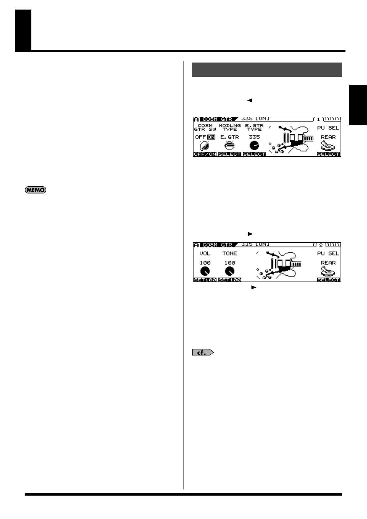
25
Chapter 2
Chapter 2 Creating Sounds
First, let’s take a look at how the VG-99 is organized internally.
●
COSM Guitars
You can use COSM modeling to create the tones of a variety of
different guitars. Available sounds include not just electric and
acoustic guitar tones, but extend beyond to include the sounds of
synthesizers and other instruments and even non-existent,
imaginary guitars. Since the created sounds are based on the signals
sent by the GK-3 for each individual string, the system allows you to
play these sounds while still retaining all the flavor created by the
unique playing techniques and picking nuances that the guitar
offers.
The VG-99 allows you to make settings for two different COSM
guitar types at the same time, enabling you to instantly switch what
amounts to two actual guitars and create sounds in which two
guitars seem to be playing at the same time.
You can use the Alternate Tuning function to change the
pitch of each COSM guitar string individually.
●
Poly Effects
These are original VG effects that can be applied independently to
each string. You can choose which of the two COSM guitars the
effects are applied to.
●
COSM Amps
Since this technology models the guitar amp circuitry and speaker
characteristics, the modeled amps simulate exactly the behavior of
the actual amps, even in the way distortion is added and the way the
tone controls work.
You can configure preamps and speaker cabinets as you like—you
can even model the amp’s studio miking. The VG-99 produces two
independent COSM amp systems at the same time, which allows
you to process each of the two COSM guitars through a different
amp.
●
Effects
The VG-99 is equipped with two BOSS GT-PRO class multi-effects
systems. You can apply effects separately to each of the two COSM
guitars.
●
Mixer
In addition to having full freedom in mixing the sounds from the
two COSM guitars, you can also output the two guitars separately to
MAIN OUT and SUB OUT. The Dynamifunction further allows you
to use the force of your picking attack to switch between the two
guitar sounds or for many other functions. Furthermore, the mixer
section also includes delay/reverb and an equalizer, enabling you to
adjust the overall tone of the patches.
1.
Press [MODELING TYPE].
2.
Press PAGE [ ] several times to display Page
1.
3.
Use [F1] (ON/OFF) or the F1 knob to switch the
COSM GUITAR ON/OFF setting.
4.
Use [F2] (SELECT) or the F2 knob to select the
Modeling type.
5.
Use [F3] (SELECT) or the F3 knob to select the
COSM GUITAR type.
6.
Press PAGE [ ].
* Each press of PAGE [ ] takes you to the next screen in which
parameter settings are made.
7.
Adjust the desired parameter with [F1]–[F6] or
the F1–F6 knobs.
8.
Adjust the parameters until you achieve the
sound you want.
For detailed information about each of the parameters,
refer to
“COSM GUITAR”
(p. 101).
9.
If you want to save the edited settings,
perform the Write procedure (p. 38).
* If you do not want to save, press [EXIT] to return to the Play screen.
Setting the COSM GUITAR Tone
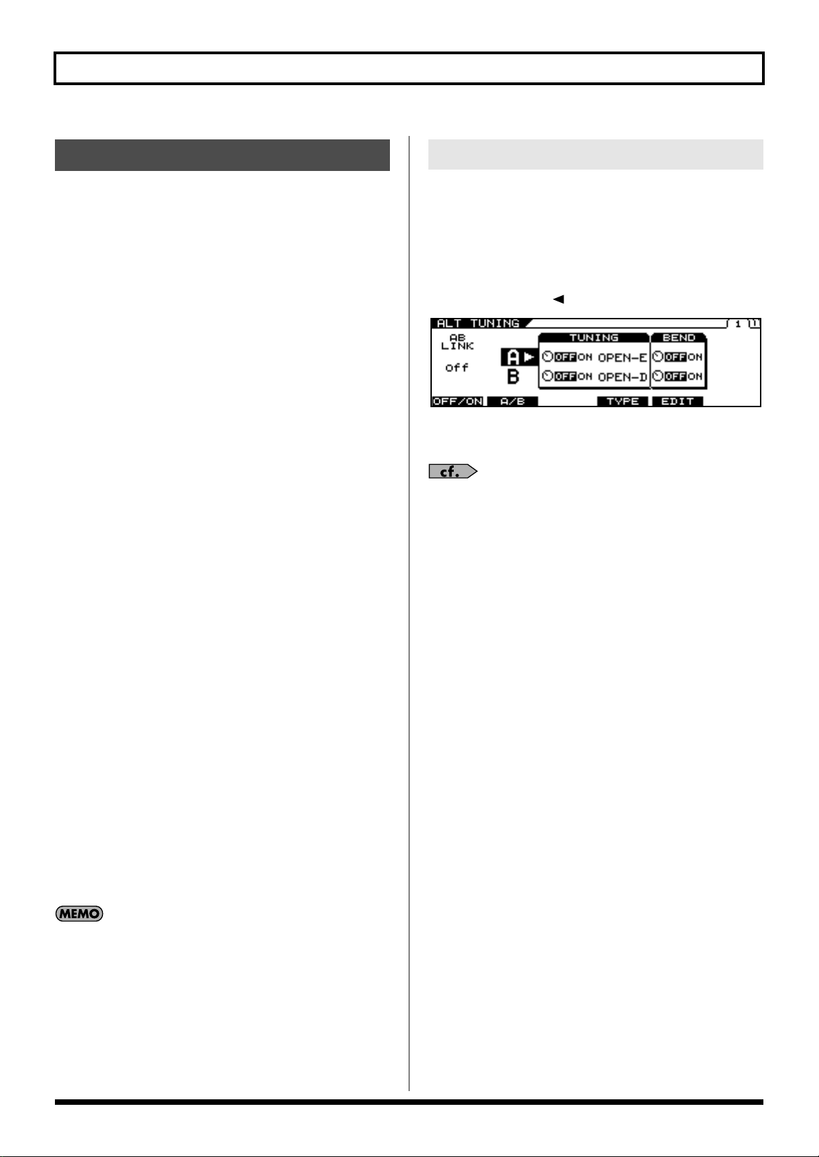
26
Chapter 2 Creating Sounds
About Alternate Tuning
Maybe insert a sentence in the beginning of this:
The Alternate Tuning feature allows you to change the tuning of a
COSM guitar without changing the actual pitch of the guitar’s
strings. To accomplish this, the VG-99 analyzes the pitch of the
signals transmitted by the divided pickup for each individual string
while keeping best possible sound quality.
Alternate Tuning includes the following five functions.
TUNING
Use this to convert the tuning to open tunings such as OPEN-D and
OPEN-G, raise or lower all of the strings an octave, and achieve
various other tunings.
BEND
You can use a pedal to have pitches change from the current tuning
to the set tuning in a continuous transition, just as with a string
bender or pedal steel guitar.
12-STRING
This changes the sound of a regular six-string guitar to that of a
twelve-string guitar.
This function also gives you the freedom to set the pitch and volume
of each secondary string independently, enabling you to create 12-
string guitar models with entirely original tunings.
DETUNE
This allows you to set a subtle shift in the pitch of each individual
string.
HARMONY
This analyzes the pitch of each string, then converts the pitches into
harmonies matched to the key.
These functions can be set for each of the two COSM guitars A and B
individually, meaning you can now play six-string and twelve-string
guitars simultaneously, produce twin twin leads by creating
harmonies on your own, achieve fat unison sounds, and come up
with sounds never before possible, all with a single VG-99.
Additionally, the VG-99 includes an AB LINK function, which
allows you to set the TUNING and BEND for the two COSM guitars
(A and B) simultaneously for even quicker settings.
The pitches output with GUITAR TO MIDI (the MIDI
Note messages) change according to the Channel A
Alternate Tuning settings (TUNING, BEND, HARMO).
* The Channel B Alternate Tuning settings have no bearing on these
output pitches.
* If the pitch output with GUITAR TO MIDI (the MIDI Note
messages) is excessively low (or high) due to the influence of the
Channel A Alternate Tuning settings, the pitch is then
automatically set one octave higher (or lower).
Setting AB LINK to ON allows you to use the same TUNING and
BEND settings for COSM GUITAR [A] and COSM GUITAR [B].
When this is set to OFF, you can use different settings for COSM
GUITAR [A] and COSM GUITAR [B].
1.
Press [ALTERNATE TUNING].
2.
Press PAGE [ ] to display Page 1.
fig.01-060d
3.
Switch AB LINK on or off with [F1] (OFF/ON) or
the F1 knob.
For detailed information on all the parameters, refer to
“ALTERNATE TUNING”
(p. 116).
Setting the Alternate Tuning
Setting AB LINK
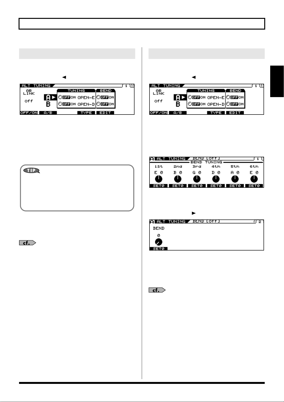
27
Chapter 2 Creating Sounds
Chapter 2
1.
Press [ALTERNATE TUNING].
2.
Press PAGE [ ] to display Page 1.
fig.01-060d
3.
Select A or B with [F2] (A/B) or the F2 knob.
* You cannot select this when AB LINK is on.
4.
Switch the function on or off with the F3 knob.
5.
Select the tuning TYPE with [F4] (TYPE) or the
F4 knob.
6.
If you want to save the edited settings,
perform the Write procedure (p. 38).
* If you do not want to save, press [EXIT] to return to the Play screen.
For detailed information on all the parameters, refer to
“ALTERNATE TUNING”
(p. 116).
1.
Press [ALTERNATE TUNING].
2.
Press PAGE [ ] to display Page 1.
fig.01-060d
3.
Select A or B with [F2] (A/B) or the F2 knob.
* You cannot select this when AB LINK is on.
4.
Switch the function on or off with the F5 knob.
5.
Press [F5] (EDIT).
fig.01-060d
6.
Set the pitches you want the strings to bend to
with the F1–F6 knobs.
7.
Press PAGE [ ] to display Page 2.
fig.01-060d
8.
Confirm the change in pitch with the F1 knob.
9.
With Control Assign, set BEND as the target
parameter for the pedal being used to control
the pitch.
For detailed information on Control Assign, refer to
“Using the Switches, Pedals, and MIDI to Control the
Sounds (CONTROL ASSIGN)”
(p. 82).
Setting TUNING
You can set original user tunings when USER is
selected for TYPE. (p. 29)
• Press [F3] (USER).
• Set the desired parameter with [F1]–[F6] or with the F1–F6
knobs.
• Press [EXIT].
Setting BEND
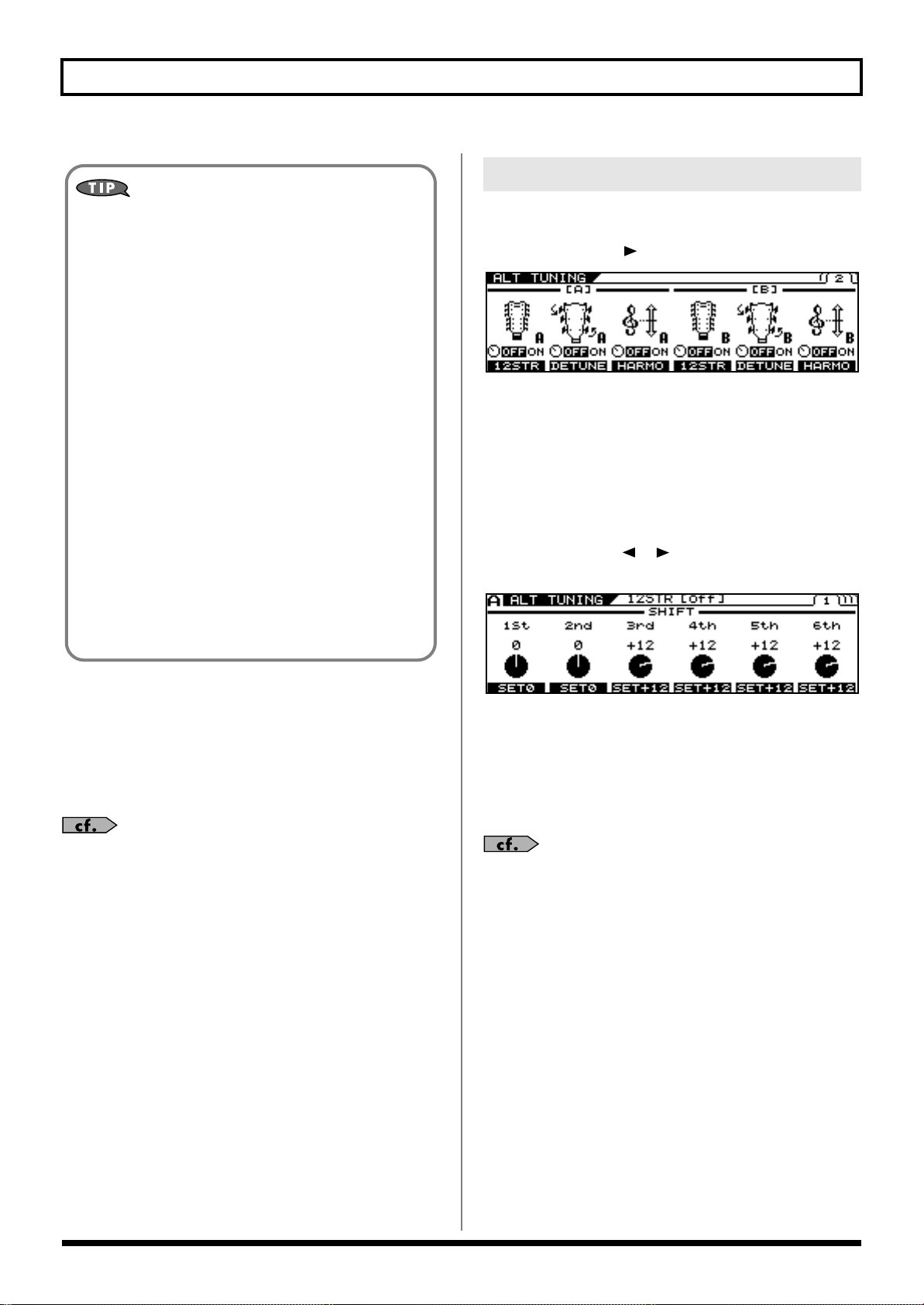
28
Chapter 2 Creating Sounds
10.
If you want to save the edited settings,
perform the Write procedure (p. 38).
* If you do not want to save, press [EXIT] to return to the Play screen.
* Although parameter assignments set with Control Assign are saved
with the Write procedure, the BEND parameter values in Step 8 are
not saved.
For detailed information on all the parameters, refer to
“ALTERNATE TUNING”
(p. 116).
1.
Press [ALTERNATE TUNING].
2.
Press PAGE [ ] to go to Page 2.
fig.01-060d
3.
Switch the function on or off with the F1 or F4
knob.
* You can make separate 12 STRING settings for COSM GUITAR
[A] and COSM GUITAR [B].
4.
If making detailed parameter settings for 12
STRINGS, press [F1] (12STR) or [F4] (12STR).
5.
Press PAGE [ ] [ ] to display the parameter
you want to set.
fig.01-060d
6.
Set the desired parameter with [F1]–[F6] or
with the F1–F6 knobs.
7.
If you want to save the edited settings,
perform the Write procedure (p. 38).
* If you do not want to save, press [EXIT] to return to the Play screen.
For detailed information on all the parameters, refer to
“ALTERNATE TUNING”
(p. 116).
Example of BEND Parameter Settings
By making the parameter settings shown below, you can
achieve a string bender-like effect which smoothly raises the
pitch of the second string a whole step.
Values Set for the Alternate Tuning Parameter
[ALT TUNING]
AB LINK = ON
BEND SW = ON
BEND TUNING 1st = E 0
BEND TUNING 2nd = D +2
BEND TUNING 3rd = G 0
BEND TUNING 4th = D 0
BEND TUNING 5th = A 0
BEND TUNING 6th = E 0
Values Set for the Control Assign Parameter
[CONTROL ASSIGN]
SOURCE = FC-300 EXP 1 or RIBBON POS
(Set the RIBBON CONTROLLER’s ASSIGNABLE
setting to ON.)
SW = ON
TARGET PARAMETER = ALT TUNE/[A]BEND/BEND
Setting 12-STRING

29
Chapter 2 Creating Sounds
Chapter 2
1.
Press [ALTERNATE TUNING].
2.
Press PAGE [ ] to display Page 1.
fig.01-060d
3.
Select A or B with [F2] (A/B) or the F2 knob.
* You cannot select this when AB LINK is on.
4.
Switch the function on or off with the F3 knob.
5.
Use [F4] (TYPE) or the F4 knob to select USER.
6.
Press [F3] (USER).
The USER TUNING screen appears.
7.
Set the desired key of string with [F1]–[F6] or
with the F1–F6 knobs.
8.
If you want to save the edited settings,
perform the Write procedure (p. 38).
* If you do not want to save, press [EXIT] to return to the Play screen.
For detailed information on all the parameters, refer to
“ALTERNATE TUNING”
(p. 116).
1.
Press [ALTERNATE TUNING].
2.
Press PAGE [ ] to go to Page 2.
fig.01-060d
3.
Switch the function on or off with the F2 or F5
knob.
4.
If making detailed parameter settings for
DETUNE, press [F2] (DETUNE) or [F5]
(DETUNE).
fig.01-060d
5.
Set the desired parameter with [F1]–[F6] or
with the F1–F6 knobs.
6.
If you want to save the edited settings,
perform the Write procedure (p. 38).
* If you do not want to save, press [EXIT] to return to the Play screen.
For detailed information on all the parameters, refer to
“ALTERNATE TUNING”
(p. 116).
Setting USER TUNING
Setting DETUNE

30
Chapter 2 Creating Sounds
1.
Press [ALTERNATE TUNING].
2.
Press PAGE [ ] to go to Page 2.
fig.01-060d
3.
Switch the function on or off with the F3 or F6
knob.
4.
If making detailed parameter settings for
HARMONY, press [F3] (HARMO) or [F6]
(HARMO).
fig.01-060d
5.
Set the desired parameter with [F1] (SELECT),
[F2] (SELECT) or with the F1–F2 knobs.
6.
If you want to save the edited settings,
perform the Write procedure (p. 38).
* If you do not want to save, press [EXIT] to return to the Play screen.
For detailed information on all the parameters, refer to
“ALTERNATE TUNING”
(p. 116).
1.
Press [COSM AMP].
2.
Press PAGE [ ] several times to display Page
1.
3.
Use [F1] (ON/OFF) or the F1 knob to switch the
COSM AMP ON/OFF setting.
fig.01-060d
4.
Use [F2] (SELECT) or the F2 knob to select the
COSM AMP type.
5.
Press PAGE [ ].
fig.01-060d
* Each press of PAGE [ ] takes you to the next screen in which
parameter settings are made.
6.
Adjust the desired parameter with [F1]–[F6] or
the F1–F6 knobs.
7.
Adjust the parameters until you achieve the
sound you want.
For detailed information on all the parameters, refer to
“COSM AMP”
(p. 140).
8.
If you want to save the edited settings,
perform the Write procedure (p. 38).
* If you do not need to save the settings, press [EXIT] to return to the
Play screen.
Setting HARMONY
You can set the pitch for each key when the
HARMO parameter is set to USER.
Press PAGE [ ] [ ] to display the parameter you
want to set.
Setting the COSM AMP Tone
 Loading...