


 Loading...
Owner’s Manual
Thank you, and congratulations on your choice of the Roland Digital Piano RD-700.
Before using this unit, carefully read the sections entitled: “IMPORTANT SAFETY INSTRUCTIONS” (p. 2), “USING THE UNIT SAFELY” (p. 3), and “IMPORTANT NOTES” (p. 5).
These sections provide important information concerning the proper operation of the unit. Additionally, in order to feel assured that you have gained a good grasp of every feature provided by your new unit, Owner’s Manual should be read in its entirety. The manual should be saved and kept on hand as a convenient reference.
.
Copyright © 2001 ROLAND CORPORATION
All rights reserved. No part of this publication may be reproduced in any form without the written permission of ROLAND CORPORATION.
CAUTION
RISK OF ELECTRIC SHOCK
DO NOT OPEN
ATTENTION: RISQUE DE CHOC ELECTRIQUE NE PAS OUVRIR
CAUTION: TO REDUCE THE RISK OF ELECTRIC SHOCK,
DO NOT REMOVE COVER (OR BACK).
NO USER-SERVICEABLE PARTS INSIDE.
REFER SERVICING TO QUALIFIED SERVICE PERSONNEL.
The lightning flash with arrowhead symbol, within an equilateral triangle, is intended to alert the user to the presence of uninsulated “dangerous voltage” within the product’s enclosure that may be of sufficient magnitude to constitute a risk of electric shock to persons.
The exclamation point within an equilateral triangle is intended to alert the user to the presence of important operating and maintenance (servicing) instructions in the literature accompanying the product.
INSTRUCTIONS PERTAINING TO A RISK OF FIRE, ELECTRIC SHOCK, OR INJURY TO PERSONS.
IMPORTANT SAFETY INSTRUCTIONS SAVE THESE INSTRUCTIONS
WARNING - When using electric products, basic precautions should always be followed, including the following:
1.Read these instructions.
2.Keep these instructions.
3.Heed all warnings.
4.Follow all instructions.
5.Do not use this apparatus near water.
6.Clean only with a dry cloth.
7.Do not block any of the ventilation openings. Install in accordance with the manufacturers instructions.
8.Do not install near any heat sources such as radiators, heat registers, stoves, or other apparatus (including amplifiers) that produce heat.
9.Do not defeat the safety purpose of the polarized or grounding-type plug. A polarized plug has two blades with one wider than the other. A grounding type plug has two blades and a third grounding prong. The wide blade or the third prong are provided for your safety. When the provided plug does not fit into your outlet, consult an electrician for replacement of the obsolete outlet.
10.Protect the power cord from being walked on or pinched particularly at plugs, convenience receptacles, and the point where they exit from the apparatus.
11.Only use attachments/accessories specified by the manufacturer.
12.Never use with a cart, stand, tripod, bracket, or table except as specified by the manufacturer, or sold with the apparatus. When a cart is used, use caution when moving the cart/apparatus combination to avoid injury from tip-over.
13.Unplug this apparatus during lightning storms or when unused for long periods of time.
14.Refer all servicing to qualified service personnel. Servicing is required when the apparatus has been damaged in any way, such as power-supply cord or plug is damaged, liquid has been spilled or objects have fallen into the apparatus, the apparatus has been exposed to rain or moisture, does not operate normally, or has been dropped.
For the U.K.
IMPORTANT: THE WIRES IN THIS MAINS LEAD ARE COLOURED IN ACCORDANCE WITH THE FOLLOWING CODE.
BLUE: NEUTRAL
BROWN: LIVE
As the colours of the wires in the mains lead of this apparatus may not correspond with the coloured markings identifying the terminals in your plug, proceed as follows:
The wire which is coloured BLUE must be connected to the terminal which is marked with the letter N or coloured BLACK.
The wire which is coloured BROWN must be connected to the terminal which is marked with the letter L or coloured RED. Under no circumstances must either of the above wires be connected to the earth terminal of a three pin plug.
2
USING THE UNIT SAFELY
Used for instructions intended to alert the user to the risk of death or severe injury should the unit be used improperly.
Used for instructions intended to alert the user to the risk of injury or material damage should the unit be used improperly.
* Material damage refers to damage or other adverse effects caused with respect to the home and all its furnishings, as well to domestic animals or pets.
The symbol alerts the user to important instructions or warnings.The specific meaning of the symbol is determined by the design contained within the triangle. In the case of the symbol at left, it is used for general cautions, warnings, or alerts to danger.
The  symbol alerts the user to items that must never be carried out (are forbidden). The specific thing that must not be done is indicated by the design contained within the circle. In the case of the symbol at left, it means that the unit must never be disassembled.
The ● symbol alerts the user to things that must be carried out. The specific thing that must be done is indicated by the design contained within the circle. In the case of the symbol at left, it means that the powercord plug must be unplugged from the outlet.
001
•Before using this unit, make sure to read the instructions below, and the Owner’s Manual.
..........................................................................................................
002b
• Do not open or perform any internal modifica-
tions on the unit. (The only exception would be where this manual provides specific instructions
which should be followed in order to put in place user-installable options; see p. 15.)
..........................................................................................................
003
•Do not attempt to repair the unit, or replace parts within it (except when this manual provides specific instructions directing you to do so). Refer
all servicing to your retailer, the nearest Roland Service Center, or an authorized Roland distributor, as listed on the “Information” page.
..........................................................................................................
004
• Never use or store the unit in places that are:
• Subject to temperature extremes (e.g., direct sunlight in an enclosed vehicle, near a heating duct, on top of heat-generating equipment); or are
•Damp (e.g., baths, washrooms, on wet floors); or are
•Humid; or are
•Exposed to rain; or are
•Dusty; or are
•Subject to high levels of vibration.
..........................................................................................................
005
•This unit should be used only with a rack or stand that is recommended by Roland.
..........................................................................................................
008e
•Use only the attached power-supply cord. Also, the supplied power cord must not be used with any other device.
..........................................................................................................
006
•When using the unit with a rack or stand recommended by Roland, the rack or stand must be carefully placed so it is level and sure to remain stable. If not using a rack or stand, you still need
to make sure that any location you choose for placing the unit provides a level surface that will properly support the unit, and keep it from wobbling.
..........................................................................................................
008a
• The unit should be connected to a power supply only of the type described in the operating instructions, or as marked on the unit.
..........................................................................................................
009
•Do not excessively twist or bend the power cord, nor place heavy objects on it. Doing so can damage the cord, producing severed elements and short circuits. Damaged cords are fire and shock
hazards!
..........................................................................................................
010
•This unit, either alone or in combination with an amplifier and headphones or speakers, may be capable of producing sound levels that could cause permanent hearing loss. Do not operate for a long period of time at a high volume level, or at a level that is uncomfortable. If you experience
any hearing loss or ringing in the ears, you should immediately stop using the unit, and consult an audiologist.
..........................................................................................................
011
•Do not allow any objects (e.g., flammable material, coins, pins); or liquids of any kind (water, soft drinks, etc.) to penetrate the unit.
..........................................................................................................
013
•In households with small children, an adult should provide supervision until the child is capable of following all the rules essential for the
safe operation of the unit.
..........................................................................................................
3
014
•Protect the unit from strong impact. (Do not drop it!)
..........................................................................................................
015
•Do not force the unit’s power-supply cord to share an outlet with an unreasonable number of other devices. Be especially careful when using extension cords—the total power used by all devices you have connected to the extension cord’s outlet must never exceed the power rating (watts/amperes) for the extension cord. Excessive loads can cause the insulation on the cord to heat
up and eventually melt through.
..........................................................................................................
016
•Before using the unit in a foreign country, consult with your retailer, the nearest Roland Service Center, or an authorized Roland distributor, as listed on the “Information” page.
..........................................................................................................
022a
• Always turn the unit off and unplug the power
cord before attempting installation of the circuit board (p. 25).
..........................................................................................................
026
•Do not put anything that contains water (e.g., flower vases) on this unit. Also, avoid the use of insecticides, perfumes, alcohol, nail polish, spray cans, etc., near the unit. Swiftly wipe away any
liquid that spills on the unit using a dry, soft cloth.
..........................................................................................................
101a
•The unit should be located so that its location or position does not interfere with its proper ventilation.
..........................................................................................................
101c
•This (RD-700) for use only with Roland stand KS17. Use with other stands is capable of resulting in instability causing possible injury.
..........................................................................................................
102b
• Always grasp only the plug on the power-supply
cord when plugging into, or unplugging from, an outlet or this unit.
..........................................................................................................
103a:
•At regular intervals, you should unplug the power plug and clean it by using a dry cloth to wipe all dust and other accumulations away from its prongs. Also, disconnect the power plug from the power outlet whenever the unit is to remain unused for an extended period of time. Any accumulation of dust between the power plug and the power outlet can result in poor insulation and
lead to fire.
..........................................................................................................
104
•Try to prevent cords and cables from becoming entangled. Also, all cords and cables should be placed so they are out of the reach of children.
..........................................................................................................
106
•Never climb on top of, nor place heavy objects on the unit.
..........................................................................................................
107b
• Never handle the power cord or its plugs with wet hands when plugging into, or unplugging from, an outlet or this unit.
..........................................................................................................
108a
• Before moving the unit, disconnect the power
plug from the outlet, and pull out all cords from external devices.
..........................................................................................................
109a
• Before cleaning the unit, turn off the power and unplug the power cord from the outlet (p. 25).
..........................................................................................................
110a
• Whenever you suspect the possibility of lightning
in your area, pull the plug on the power cord out of the outlet.
..........................................................................................................
115a
•Install only the specified circuit boards (SRX Series). Remove only the specified screws (p. 15).
..........................................................................................................
118
•Should you remove the screws fastening the board slot cover, make sure to put them in a safe place out of children's reach, so there is no chance of them being swallowed accidentally.
..........................................................................................................
4

IMPORTANT NOTES
291b
In addition to the items listed under “IMPORTANT SAFETY INSTRUCTIONS” and “USING THE UNIT SAFELY” on pages 2, 3 and 4, please read and observe the following:
Power Supply
301
•Do not connect this unit to same electrical outlet that is being used by an electrical appliance that is controlled by an inverter (such as a refrigerator, washing machine, microwave oven, or air conditioner), or that contains a motor. Depending on the way in which the electrical appliance is used, power supply noise may cause this unit to malfunction or may produce audible noise. If it is not practical to use a separate electrical outlet, connect a power supply noise filter between this unit and the electrical outlet.
307
•Before connecting this unit to other devices, turn off the power to all units. This will help prevent malfunctions and/or damage to speakers or other devices.
308
•Although the LCD and LEDs are switched off when the POWER switch is switched off, this does not mean that the unit has been completely disconnected from the source of power. If you need to turn off the power completely, first turn off the POWER switch, then unplug the power cord from the power outlet. For this reason, the outlet into which you choose to connect the power cord’s plug should be one that is within easy reach.
Placement
351
•Using the unit near power amplifiers (or other equipment containing large power transformers) may induce hum. To alleviate the problem, change the orientation of this unit; or move it farther away from the source of interference.
352
•This device may interfere with radio and television reception. Do not use this device in the vicinity of such receivers.
354a
•Do not expose the unit to direct sunlight, place it near devices that radiate heat, leave it inside an enclosed vehicle, or otherwise subject it to temperature extremes. Excessive heat can deform or discolor the unit.
355
•To avoid possible breakdown, do not use the unit in a wet area, such as an area exposed to rain or other moisture.
358
•Do not allow objects to remain on top of the keyboard. This can be the cause of malfunction, such as keys ceasing to produce sound.
Maintenance
401a
•For everyday cleaning wipe the unit with a soft, dry cloth or one that has been slightly dampened with water. To remove stubborn dirt, use a cloth impregnated with a mild, non-abrasive detergent. Afterwards, be sure to wipe the unit thoroughly with a soft, dry cloth.
402
•Never use benzine, thinners, alcohol or solvents of any kind, to avoid the possibility of discoloration and/or deformation.
Additional Precautions
551
•Please be aware that the contents of memory can be irretrievably lost as a result of a malfunction, or the improper operation of the unit. To protect yourself against the risk of loosing important data, we recommend that you periodically save a backup copy of important data you have stored in the unit’s memory in another MIDI device (e.g., a sequencer).
552
•Unfortunately, it may be impossible to restore the contents of data that was stored in another MIDI device (e.g., a sequencer) once it has been lost. Roland Corporation assumes no liability concerning such loss of data.
553
•Use a reasonable amount of care when using the unit’s buttons, sliders, or other controls; and when using its jacks and connectors. Rough handling can lead to malfunctions.
554
• Never strike or apply strong pressure to the display.
556
•When connecting / disconnecting all cables, grasp the connector itself—never pull on the cable. This way you will avoid causing shorts, or damage to the cable’s internal elements.
557
•A small amount of heat will radiate from the unit during normal operation.
558a
•To avoid disturbing your neighbors, try to keep the unit’s volume at reasonable levels. You may prefer to use headphones, so you do not need to be concerned about those around you (especially when it is late at night).
559a
•When you need to transport the unit, package it in the box (including padding) that it came in, if possible. Otherwise, you will need to use equivalent packaging materials.
561
•Use only the specified expression pedal (EV-5; sold separately). By connecting any other expression pedals, you risk causing malfunction and/or damage to the unit.
5
Main Features
Progressive Hammer Action
The RD-700 features a “progressive hammer action,” a new and even more advanced form of Roland's popular keyboard hammer action that realistically reproduces the comfortable, natural touch of a grand piano. Basic percussive and damper functions are also improved, recreating the subtle changes in touch occurring between registers as you move across the keyboard.
In addition, the progressive hammer action keyboard has been designed with consideration given to the environment, and the hammer section is completely lead-free.
New Piano Tones
The RD-700's authentic piano Tones feature wide dynamic range and rich expressive power. It is also furnished with a wealth of electronic piano, organ, string, synth pad, and other Tones that allow you to use the instrument as a stage piano. Once you try it onstage, you'll come to fully understand its capabilities.
Also included is a “Piano Edit” function that allows you to make subtle changes to the piano Tones, allowing you to create Tones for all kinds of performance situations (p. 66).
A Full 128 Voices
The RD-700 features 128-voice polyphony, with all sounds available in every performance mode. Enjoy natural performances even when layering multiple sounds.
Simple Push-Button Operation
You can access Split and Layer modes and carry out other main operations simply by pressing a single button (p. 41).
Furthermore, pressing the ONE TOUCH [PIANO] button lets you immediately switch to the settings most suited for piano performances, regardless of the mode or settings currently in effect (p. 35).
Full-Graphic LCD Screen
The panel includes a high-visibility fully graphic liquid crystal display. This allows you to carry out operations smoothly while viewing Tone names and other information in the easy-to-read LCD screen.
High-Quality Effects
In addition to favorite Roland synthesizer and XV Series multi-effects, the RD-700 also features a sympathetic resonance effect that reproduces the resonance of an acoustic piano. You can also get realistic tone changes by pressing the damper pedal (p. 76). And the digital equalizer lets you make an even wider range of Tone adjustments (p. 73).
Equipped With Organ Tone Wheel
Sound Generator
For organ Tones, the RD-700 comes equipped with an organ Tone wheel sound generator used in the Roland Combo Organ VK-7. This sound generator lets you recreate organ sounds, changing the level of each footage (p. 75).
Rhythm and Arpeggiator Functions
You can play back Rhythm patterns and perform arpeggios with the press of a single button.
Enjoy a variety of performance techniques, with backing using realistic drum sounds for a real session feel, arpeggios and cutting you get just by playing the chords, and more (p. 49, p. 51).
Fast MIDI Control
You can also control various functions, such as adjusting volume levels and selecting Tones, simply and easily from an external MIDI device. This provides fast and intuitive control when using the keyboard on stage (p. 59).
Expandability
You can install up to two SRX Series Wave Expansion Boards, a favorite for use with Roland's XV Series. Starting with the “SRX-02 Concert Grand” Tone, you can enjoy performing with the most up-to-date Tones available as they are continually released (p. 15).
Sophisticated Design
The great-looking titanium-colored instrument body makes for a top-class onstage image. With simple rear cable connections, the design also shows that due consideration has been given to operability.
GM/GM2 Compatible
The RD-700 is compatible with both General MIDI and General MIDI 2 standards. When working with music files that conforms to General MIDI and/or General MIDI 2 (GM scores), you can combine the RD-700 with a sequencer, and use the RD-700 to play back the data.
Convention Used in This Manual
•Words enclosed in square brackets [ ] indicate panel buttons.
Example: [SPLIT] indicates the SPLIT button.
•(p. **) indicates a reference page
•The explanations in this manual include illustrations that depict what should typically be shown by the display. Note, however, that your unit may incorporate a newer, enhanced version of the system (e.g., includes newer sounds), so what you actually see in the display may not always match what appears in the manual.
6

Contents
USING THE UNIT SAFELY...................................................................................................................... |
3 |
IMPORTANT NOTES................................................................................................................................ |
5 |
Main Features ............................................................................................................. |
6 |
Panel Descriptions................................................................................................... |
12 |
Getting Ready........................................................................................................... |
15 |
Installing the Wave Expansion Board ................................................................................................... |
15 |
Cautions When Installing an Wave Expansion Board............................................................. |
15 |
Installing SRX Series Boards........................................................................................................ |
16 |
Checking the Installed Wave Expansion Boards...................................................................... |
18 |
Installation de la carte d’extension Wave (French language for Canadian Safety Standard) ....... |
19 |
Precautions lors de l’installation de la carte d’extension Wave ............................................. |
19 |
Installer les cartes de série SRX ................................................................................................... |
20 |
Vérification des cartes d’extension audio aprés installation .................................................. |
21 |
Connecting the RD-700 to External Equipment................................................................................... |
22 |
Connecting Pedals......................................................................................................................... |
23 |
Turning the Power On and Off .............................................................................................................. |
24 |
Turning On the Power.................................................................................................................. |
24 |
Turning Off the Power ................................................................................................................. |
25 |
Adjusting the Volume.............................................................................................................................. |
25 |
Restoring the Factory Settings (Factory Reset)..................................................................................... |
26 |
Adjusting the Display Contrast (LCD Contrast).................................................................................. |
28 |
Tuning to Other Instruments’ Pitches (Master Tune) ......................................................................... |
29 |
Overview of the RD-700 ........................................................................................... |
31 |
Basic Organization of the RD-700 .......................................................................................................... |
31 |
Units of Sound .......................................................................................................................................... |
31 |
Tone................................................................................................................................................. |
31 |
Part .................................................................................................................................................. |
31 |
Basic Operation of the RD-700................................................................................................................ |
32 |
Main Screens .................................................................................................................................. |
32 |
Special Indications ........................................................................................................................ |
32 |
About the Function Buttons ........................................................................................................ |
32 |
About the CURSOR Buttons........................................................................................................ |
33 |
Changing the Settings Values...................................................................................................... |
33 |
Listening to the Demo (DEMO PLAY)..................................................................... |
34 |
Performing with the Keyboard................................................................................ |
35 |
Piano Performances (One Touch [Piano])............................................................................................. |
35 |
Performing with a Variety of Tones ...................................................................................................... |
36 |
Specifying the Tone Number to Select a Tone ([NUM LOCK]) ............................................. |
37 |
Playing a Rhythm Set ................................................................................................................... |
38 |
Selecting Wave Expansion Board Tones.................................................................................... |
39 |
Playing Two Tones on the Keyboard .................................................................................................... |
41 |
To Switch to Single Mode ............................................................................................................ |
41 |
Playing with Two Layered Tones ([LAYER]) ........................................................................... |
42 |
Playing Different Tones in Two Different Sections of the Keyboard ([SPLIT]) ................... |
43 |
Changing Tones in Layer and Split Mode................................................................................. |
44 |
Adjust the Volume Level for Individual Parts (PART SWITCH/LEVEL) ...................................... |
45 |
Transposing the Key of the Keyboard ([TRANSPOSE])..................................................................... |
46 |
Adding Reverberation to the Sound (REVERB knob)......................................................................... |
47 |
7

Contents
Adding Breadth to the Sound (CHORUS knob) .................................................................................. |
47 |
Changing the Sound’s Pitch in Real Time (Bender/Modulation Lever).......................................... |
48 |
Adjusting the Level of the Sound’s Low, Mid, and High-Frequency Ranges (EQUALIZER)...... |
48 |
Using the Convenient Functions in Performances............................................... |
49 |
Creating Arpeggios from the Chords You Play ([ARPEGGIO]) ....................................................... |
49 |
Changing the Arpeggio Style ...................................................................................................... |
50 |
Changing Arpeggio Tempos ....................................................................................................... |
50 |
Playing Rhythm ([RHYTHM]) ............................................................................................................... |
51 |
Changing the Rhythm Pattern .................................................................................................... |
52 |
Changing Rhythm Tempos.......................................................................................................... |
52 |
Applying Effects to the Sound (MULTI EFFECTS) ............................................................................. |
53 |
Selecting Stored Settings ([SETUP])....................................................................................................... |
54 |
Storing Settings to Setups ([WRITE]) .................................................................................................... |
56 |
Using the RD-700 As a Master Keyboard............................................................... |
59 |
What’s MIDI? ............................................................................................................................................ |
59 |
About MIDI Connectors............................................................................................................... |
59 |
Connecting to External MIDI Sound Generators ..................................................................... |
59 |
MIDI Send Channel Settings................................................................................................................... |
60 |
Selecting Sounds on an External MIDI Device..................................................................................... |
61 |
Adjusting the Volume of Each Part (MIDI TX Part)............................................................................ |
62 |
Detailed Settings for Transmitted Parts ([MIDI TX]) .......................................................................... |
63 |
How to Make Settings .................................................................................................................. |
63 |
Adjusting the Volume and Pan................................................................................................... |
63 |
Setting the Amount of Reverb and Chorus ............................................................................... |
63 |
Setting the Key Range (LWR/UPR) ........................................................................................... |
63 |
Setting the Transposition for Each Individual Part (Key Transpose).................................... |
64 |
Setting the Range for the Change in Pitch with the Bender (Bend Range)........................... |
64 |
Changing Tone Elements (ATK/REL/COF/RES)................................................................... |
64 |
Smoothly Changing the Pitch (Portamento) ............................................................................. |
65 |
Changing the Pitch (Coarse Tune/Fine Tune).......................................................................... |
65 |
Turning Each Controller On and Off ......................................................................................... |
65 |
Setting the Change in Volume According to the Force Used to Play the Keyboard |
|
(Velocity) ........................................................................................................................................ |
65 |
Making Detailed Settings for the Piano Tones (Piano Edit) ................................. |
66 |
Making the settings .................................................................................................................................. |
66 |
Parameters ................................................................................................................................................. |
66 |
Selecting the Piano Sound............................................................................................................ |
66 |
Changing the Width of the Sound (Stereo Width) ................................................................... |
66 |
Changing the Sound’s Nuance (Nuance) .................................................................................. |
66 |
Changing the Sense of Space Surrounding the Sound (Ambience)....................................... |
67 |
Changing the Amount of Reverb Effect (Reverb Level).......................................................... |
67 |
Making the Midrange Equalizer Settings (EQ-SW/EQ Gain/EQ Frequency/EQ Q) ........ |
67 |
8

Contents
Detailed Settings for Each Function ([EDIT]) ........................................................ |
68 |
Parameters That Can Be Set.................................................................................................... |
68 |
Setting Parameters ........................................................................................................................ |
69 |
Making System Settings (System) .......................................................................................... |
69 |
How to Make Settings .................................................................................................................. |
69 |
Adjusting the Volume (Master Volume) ................................................................................... |
70 |
Preventing Equalizer Settings from Being Switched (EQ Control) ....................................... |
70 |
Retaining the Current Tone Even When Tones Are Switched (Tone Remain) .................... |
70 |
Changing the Clock (Timing) Source (Clock Source) .............................................................. |
70 |
Switching Between Reception of GM/GM2 System On and GS Reset................................. |
70 |
Using Program Change Messages to Switch Setups (Control Channel)............................... |
70 |
Setting the Device ID Number (Device ID) ............................................................................... |
71 |
Switching the Pedal’s Polarity (Pedal Polarity) ........................................................................ |
71 |
Setting the Keyboard Touch (Key Touch) .............................................................................. |
71 |
How to Make Settings .................................................................................................................. |
71 |
Changing the Key Touch (Key Touch)....................................................................................... |
72 |
Making Fine Adjustments to the Keyboard Touch (Key Touch Offset) ............................... |
72 |
Setting a Constant Volume Level in Response to the Playing Force (Velocity)................... |
72 |
Changing the Timing of Sounds in Response to the Velocity (Velocity Delay Sens) ......... |
72 |
Changing the Touch Sensitivity According to the Key Range (Velocity Keyfollow Sens) 72 |
|
Pedal, [CONTROL] Knob, and Equalizer Settings (Control/EQ)........................................... |
73 |
How to Make Settings .................................................................................................................. |
73 |
Assigning Functions to Pedals (FC1/FC2) ................................................................................ |
73 |
Changing the [CONTROL] Knob Settings (Control/Src) ....................................................... |
74 |
Changing the Equalizer Frequency Settings (Freq/Q)............................................................ |
74 |
Simulating the Creation of Organ Tones (Tone Wheel Mode).............................................. |
75 |
Changing the PART LEVEL Slider Feet Assignments (Harmonic Bar) ................................ |
76 |
Setting the Multi-Effects, Reverb, and Chorus Effects (MFX/Reverb/Chorus).................... |
76 |
How to Make Settings .................................................................................................................. |
76 |
Making Multi-Effects Settings ..................................................................................................... |
77 |
Making Reverb Settings ............................................................................................................... |
78 |
Setting Chorus and Delay ............................................................................................................ |
78 |
Making Tone Settings (Tone Edit)........................................................................................... |
79 |
How to Make Settings .................................................................................................................. |
79 |
Selecting the Part to Be Set (<Part>, Tone) ................................................................................ |
80 |
Setting the Reverb/Chorus Depth (Reverb/Chorus Amount) .............................................. |
80 |
Changing the Effect Applied to the Tone (MFX)...................................................................... |
80 |
Playing Sound Monophonically (MONO/POLY) ................................................................... |
80 |
Changing the Pitch (Coarse/Fine Tune).................................................................................... |
80 |
Creating Smooth Pitch Changes (Portamento Switch/Time) ................................................ |
81 |
Changing Tone Elements ............................................................................................................. |
81 |
Changing the Bend Range (Bend Range) .................................................................................. |
81 |
Precise Modification of Chord Sonorities (Stretch Tune)........................................................ |
81 |
Making the Rhythm Settings (Rhythm Pattern) ..................................................................... |
82 |
How to Make Settings .................................................................................................................. |
82 |
Adjusting the Tempo (Tempo).................................................................................................... |
82 |
Changing Patterns (Pattern) ........................................................................................................ |
82 |
Selecting Rhythm Variations (Rhythm Type) ........................................................................... |
82 |
Changing the Drum Set (Rhy Set) .............................................................................................. |
83 |
Changing the Pattern Without Changing the Drum Set (Rhy Set Change) ......................... |
83 |
Switching the Intro and Ending On or Off (Intro/Ending) .................................................... |
83 |
9

Contents
Making Arpeggio Settings (Arpeggio) .................................................................................... |
83 |
How to Make Settings .................................................................................................................. |
83 |
Adjusting the Tempo (Tempo).................................................................................................... |
84 |
Selecting Parts to Play Arpeggios (Dest. Part) .......................................................................... |
84 |
Setting the Key Range for the Arpeggio Performances (Key Range) .................................... |
84 |
Setting the Way Arpeggios are Played (Style) .......................................................................... |
84 |
Changing the octave range in arpeggio style (Octave Range) ............................................... |
85 |
Changing the Order in Which Notes Are Played (Motif) ....................................................... |
85 |
Changing the Groove Feel (Beat Pattern/Accent Rate/Shuffle Rate)................................... |
86 |
Keeping the Force of the Notes Constant (Velocity)................................................................ |
87 |
Continuing Arpeggios Even After the Keys Are Released (Arpeggio Hold) ...................... |
87 |
Keyboard Part and Controllers Settings (Local Part Param)................................................ |
87 |
How to Make Settings .................................................................................................................. |
87 |
Selecting the Part to Be Set (<Local Part>) ................................................................................ |
88 |
Setting the Key Range for Each Part (Key Range).................................................................... |
88 |
Setting the Change in Volume According to the Force Used to Play the Keyboard |
|
(Velocity Sens/Max) ..................................................................................................................... |
88 |
Setting the Transposition for Each Individual Part (Key Transpose).................................... |
88 |
Turning the Controllers in Each Part On and Off .................................................................... |
89 |
Assigning Internal Parts to Local Parts (Part Assign).............................................................. |
89 |
Setting MIDI Receive Parts (Internal Part Prm) ...................................................................... |
89 |
How to Make Settings .................................................................................................................. |
89 |
Selecting the Part to Be Set (<Part>, Tone) ................................................................................ |
90 |
Setting the Receive Channel (Receive Channel) ....................................................................... |
90 |
Setting the Volume and Pan (Volume/Pan) ............................................................................. |
90 |
Making the Effect ON/OFF Settings (MFX Switch) ................................................................ |
90 |
Setting the Required Polyphony (Voice Reserve) .................................................................... |
90 |
Setting Reception and Blocking of MIDI Messages from External MIDI Controllers ........ |
91 |
Setting the Tuning Method (Temperament/Key).................................................................... |
91 |
Other Functions (Utility)........................................................................................................... |
92 |
Transferring the RD-700’s Settings to an External MIDI Device (Bulk Dump) ................... |
92 |
Restoring the settings to the factory condition (Factory Reset).............................................. |
94 |
Connecting External MIDI Devices ......................................................................... |
95 |
Recording RD-700 Performances to an External MIDI Sequencer .................................................... |
95 |
Connecting to an External Sequencer ........................................................................................ |
95 |
Settings for Recording (Rec Setting)........................................................................................... |
95 |
Recording the Performance ......................................................................................................... |
96 |
About the Local Switch ................................................................................................................ |
96 |
Playing the RD-700’s Internal Sound Generator from an External MIDI Device ........................... |
97 |
Making connections ...................................................................................................................... |
97 |
Setting the Channels ..................................................................................................................... |
97 |
Selecting RD-700 Sounds from an External MIDI Device ....................................................... |
97 |
Using the RD-700 as a GM Sound Module (GM Mode) ..................................................................... |
98 |
Points to Note Regarding GM Mode.......................................................................................... |
98 |
Playing Back GM Scores............................................................................................................... |
98 |
10
Contents
Appendices ..................................................... |
99 |
Troubleshooting....................................................................................................... |
99 |
Error Messages/Other Messages ......................................................................... |
103 |
Effect/Parameter List ............................................................................................. |
104 |
Tone List ................................................................................................................. |
135 |
Rhythm Set List....................................................................................................................................... |
138 |
Arpeggio Style List ................................................................................................ |
142 |
Rhythm Pattern List ............................................................................................... |
143 |
Setup List................................................................................................................ |
144 |
Shortcut List ........................................................................................................... |
145 |
MIDI Implementation .............................................................................................. |
146 |
Main Specifications................................................................................................ |
164 |
Index........................................................................................................................ |
165 |
Purpose-Oriented Index ........................................................................................ |
168 |
Information ............................................................................................................. |
170 |
General MIDI
General MIDI is a set of recommendations which seeks to provide a way to go beyond the limitations of proprietary designs, and standardize the MIDI capabilities of sound generating devices. Sound generating
devices and music files that meet the General MIDI standard bear the General MIDI logo (
 ). Music files bearing the General MIDI logo can be played back using any General MIDI sound generating unit to produce essentially the same musical performance.
General MIDI 2
The upwardly compatible General MIDI 2 (

 ) recommendations pick up where the original General MIDI left off, offering enhanced expressive capabilities, and even greater compatibility. Issues that were not covered by the original General MIDI recommendations, such as how sounds are to be edited, and how effects should be handled, have now been precisely defined. Moreover, the available sounds have been expanded. General MIDI 2 compliant sound generators are capable of reliably playing back music files that carry either the General MIDI or General MIDI 2 logo.
In some cases, the conventional form of General MIDI, which does not include the new enhancements, is referred to as “General MIDI 1” as a way of distinguishing it from General MIDI 2.
11
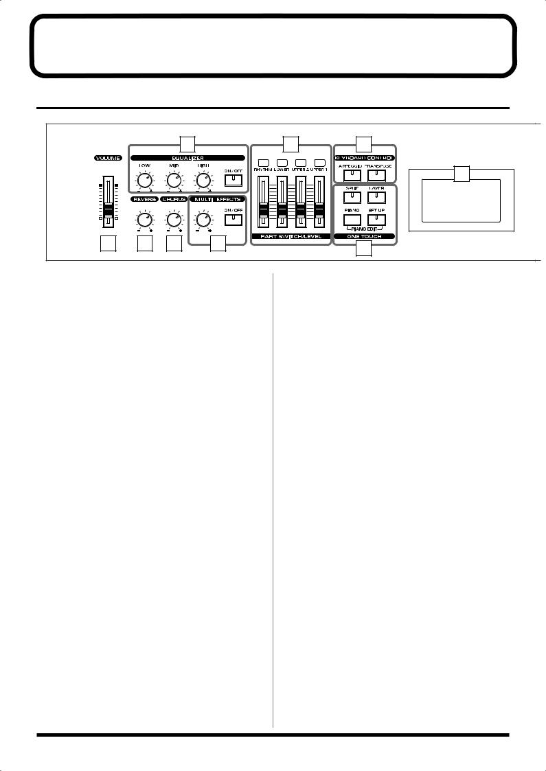
Panel Descriptions
Front Panel
|
|
|
2 |
6 |
7 |
|
|
|
|
|
9 |
|
|
|
|
CONTROL |
|
|
1 |
3 |
4 |
5 |
8 |
|
|
|
|
|
|
1 |
VOLUME Slider |
|
6 |
PART SWITCH/LEVEL |
|
Adjusts the overall volume that is output from the rear panel |
Turns each part's sound on and off (PART SWITCH), and |
||
OUTPUT jacks and PHONES jack (p. 25). |
adjusts the volume level for each part (PART LEVEL slider) |
||
|
(p. 45). |
||
2 EQUALIZER |
When [MIDI TX] is on, this controls each part for the external |
||
|
MIDI sound generator (p. 62). |
||
[ON/OFF] |
|
|
|
Turns the equalizer on/off (p. 48). |
7 |
KEYBOARD CONTROL |
|
[LOW] knob |
[ARPEGGIO] |
||
Adjusts the sound's low-frequency range. |
|||
Switches Arpeggiator on/off (p. 49). |
|||
|
|||
[MID] knob |
[TRANSPOSE] |
||
Adjusts the sound's midrange frequencies. |
|||
Sets the range of the keyboard to transposed (p. 46). |
|||
|
|||
[HIGH] knob |
8 |
ONE TOUCH |
|
Adjusts the sound's high-frequency range. |
|||
3 REVERB knob
[SPLIT]
Puts the keyboard in “Split mode,” wherein you can use Adjusts the amount of reverb (p. 47). more than one tone by having different tones play in
different parts of the keyboard (p. 43).
4 CHORUS knob
[LAYER]
Adjusts the amount of chorus (p. 47).
Puts the keyboard in “Layer mode,” in which the keyboard
plays two tones simultaneously (p. 42).
5 MULTI EFFECTS
[PIANO]
[CONTROL] knob |
Selects the optimum settings for piano performances (p. 35). |
Adjusts the way that effects are applied (p. 53).
[ON/OFF] |
[SETUP] |
Calls up the stored settings (Setup) (p. 54). |
|
Switches the multi-effects on/off (p. 53). |
Additionally, pressing [PIANO] and [SETUP] |
|
|
|
simultaneously allows you to access more detailed piano |
|
performance settings (PIANO EDIT) (p. 66). |
12
Panel Descriptions
10 |
12 |
13 |
14 |
11 |
15 |
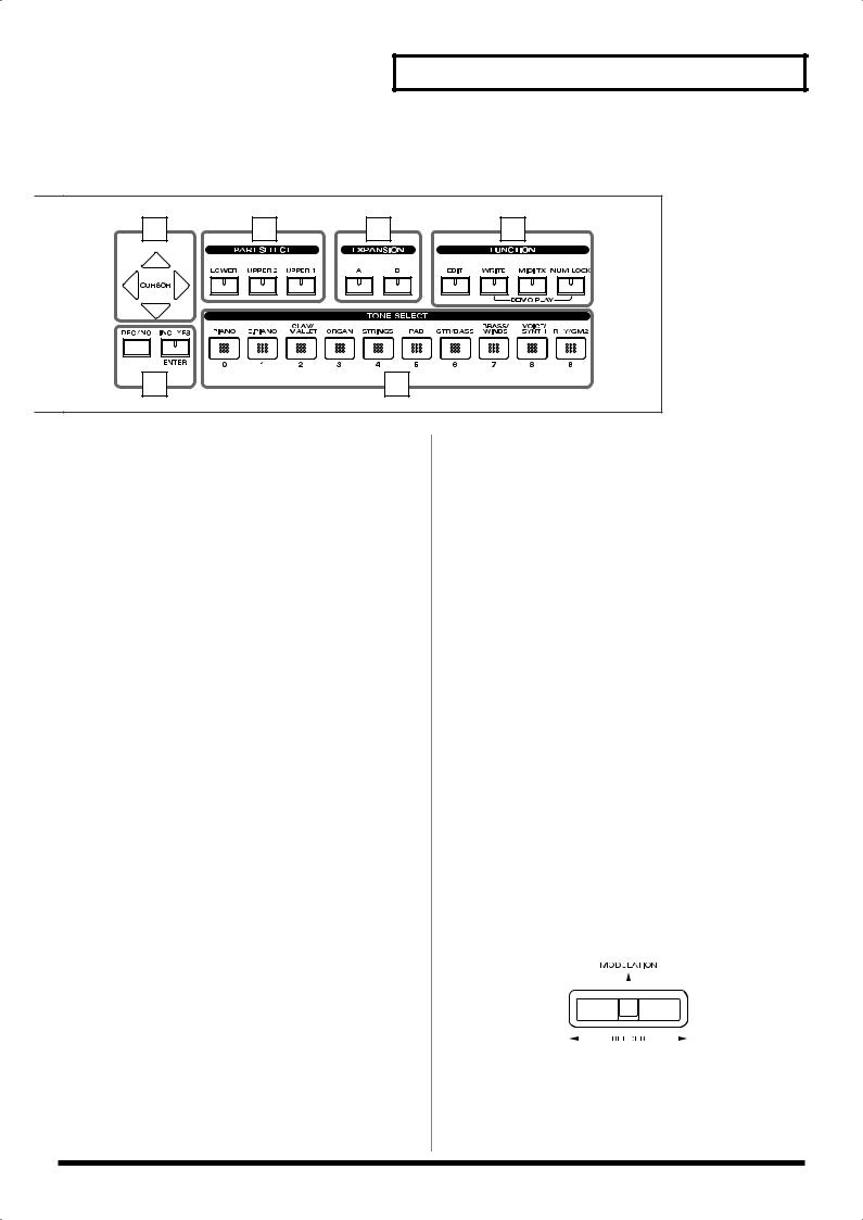
9 DISPLAY
This shows the Tone names and the values of various settings, etc (p. 32).
10 CURSOR [  ], [
], [  ], [
], [ ], [
], [  ]
]
Press these to switch pages and to move the cursor (p. 33).
11 [DEC/NO], [INC/YES]/[ENTER]
This is used to modify values.
If you keep on holding down one button while pressing the other, the value change accelerates.
Use “ENTER” to finalize a value or execute an operation.
12 PART SELECT buttons
Selects the part for which the tone is to be selected (p. 44).
13 EXPANSION [A], [B]
This selects a sound from a wave expansion board, sold separately (p. 39).
14 FUNCTION
[EDIT]
Press this button when you wish to adjust various settings (p. 68).
[WRITE]
Stores the current settings to “Setup” (p. 56).
[MIDI TX]
Puts the RD-700 in control of the external MIDI sound generator (p. 59).
[NUM LOCK]
You can input numerical values with the TONE SELECT buttons when this button is lit (p. 37).
In addition, you can listen to the demo songs by simultaneously pressing this button and [WRITE] (DEMO PLAY) (p. 34).
15 TONE SELECT buttons
Pressed to select tones (p. 36).
You can also input numerical values with these buttons when the [NUM LOCK] button is on. [NUM LOCK] turns on automatically in the Edit and other screens, enabling input of numerical values with the buttons.
Pitch Bend/Modulation Lever
This allows you to control pitch bend or apply vibrato (p. 48).
13
Panel Descriptions
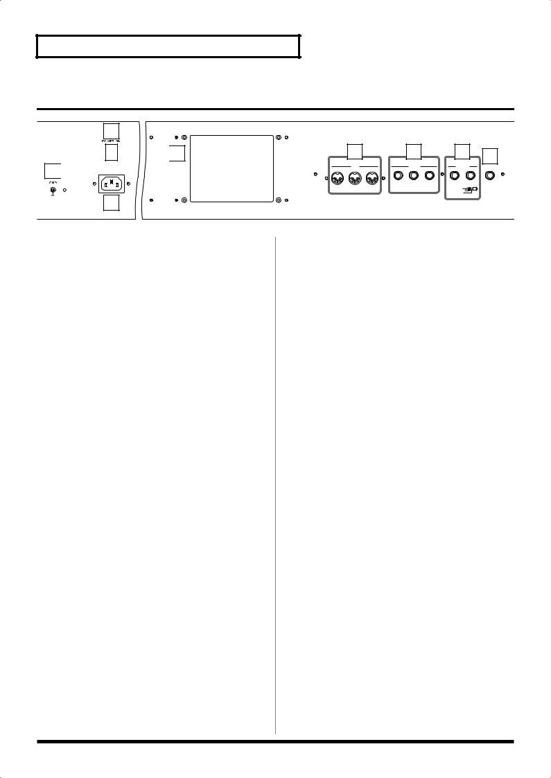
Rear Panel
2

 4 1
4 1 


3
1 GND Terminal
Connect using a grounded cable (optional) as conditions require.
In some cases, depending on the environment in which the unit is installed, the surface of the panel may sometimes feel rough and grainy. This is due to an infinitesimal electrical charge, which is absolutely harmless. However, if you are concerned about this, connect the ground terminal with an external ground. When the unit is grounded, a slight hum may occur, depending on the particulars of your installation. If you are unsure of the connection method, contact the nearest Roland Service Center, or an authorized Roland distributor, as listed on the “Information” page.
Unsuitable places for connection
-Water pipes (may result in shock or electrocution)
-Gas pipes (may result in fire or explosion)
-Telephone-line ground or lightning rod (may be dangerous in the event of lightning)
2 [POWER] Switch
Switch turns the power on/off (p. 24).
3 AC Inlet
Connect the included power cable to this inlet. (p. 22).
4Wave Expansion Board Installation Slot
Remove the cover for installation of optional wave expansion boards (SRX Series) (p. 15).
5 MIDI Connectors (IN, OUT, THRU)
Used for connecting external MIDI devices and for transmission of MIDI messages (p. 22, p. 59, p. 95).
|
5 |
|
|
6 |
|
|
7 |
8 |
|
MIDI |
|
|
PEDAL |
|
|
OUTPUT |
|
|
|
|
|
|
|
|||
THRU |
OUT |
IN |
DAMPER |
FC 1 |
FC 2 |
R |
L(MONO) |
PHONES |
|
|
|
|
|
|
BALANCED |
|
|
|
|
|
|
|
|
TIP |
HOT |
|
|
|
|
|
|
|
RING |
COLD |
|
|
|
|
|
|
|
SLEEVE |
GND |
|
6 PEDAL Jacks (DAMPER, FC1, FC2)
Connecting the pedal switch (DP-6) provided with the RD700 to the DAMPER jack allows you to use the switch as a damper pedal.
With an optional expression pedal (such as the EV-5 or other model) connected to the FC-1 or FC-2 jack, you can then assign a variety of functions to the pedal (p. 23, p. 73).
7 OUTPUT R/L (MONO) Connectors
Provide output of the audio signals. These are connected to an amp or other device. For monaural output use the L/ MONO jack (p. 22).
These also feature balanced output.
8 PHONES Jack
A set of headphones can be connected to this jack (p. 22).
Even when headphones are connected, sound will still be output from the output jacks.
14
Getting Ready
Installing the Wave Expansion Board
Up to two optional Wave Expansion Boards (SRX Series) can be installed in the RD-700.
Wave Expansion Boards store Wave data, Patches, and Rhythm Sets, and by equipping the RD-700 with these boards, you can greatly expand your sound palette.
Cautions When Installing an Wave Expansion Board
●To avoid the risk of damage to internal components that can be caused by static electricity, please carefully observe the following whenever you handle the board.
•Before you touch the board, always first grasp a metal object (such as a water pipe), so you are sure that any static electricity you might have been carrying has been discharged.
•When handling the board, grasp it only by its edges. Avoid touching any of the electronic components or connectors.
•Save the bag in which the board was originally shipped, and put the board back into it whenever you need to store or transport it.
●Use a Philips screwdriver that is suitable for the size of the screw (a number 2 screwdriver). If an unsuitable screwdriver is used, the head of the screw may be stripped.
●To remove a screw, rotate the screwdriver
counter-clockwise. To tighten a screw, rotate |
loosen |
tighten |
the screwdriver clockwise. |
|
|
●Be careful that the screws you remove do not drop into the interior of the RD-700.
●Do not leave the rear panel cover removed. After installation of the Wave Expansion Boards is complete, be sure to replace the cover.
●Do not touch any of the printed circuit pathways or connection terminals.
●Be careful not to cut your hand on the edge of the installation bay.
●Never use excessive force when installing a circuit board. If it doesn’t fit properly on the first attempt, remove the board and try again.
●When circuit board installation is complete, double-check your work.
●Always turn the unit off and unplug the power cord before attempting installation of the circuit board.
●Install only the specified circuit board(s) (SRX Series). Remove only the specified screws.
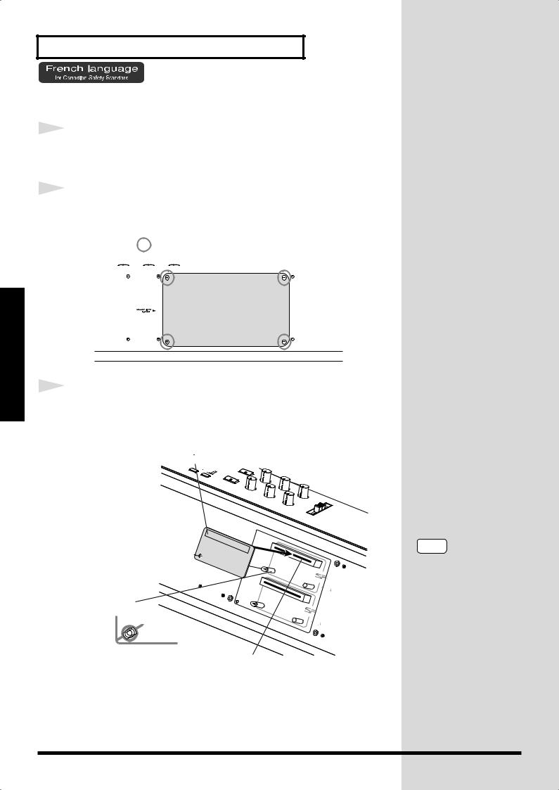
Install the Wave Expansion Boards after removing the rear panel cover. There are two slots (A and B) into which a board can be installed. Specify which slot's board is to be used by pressing EXPANSION [A] or [B] on the front panel when using waves, tones, or Rhythm Sets from the wave expansion boards.
Ready Getting
15
Getting Ready
Getting Ready
Installing SRX Series Boards
1 |
Before installing any Wave Expansion Board, turn off the |
||
|
|||
|
power on the RD-700 and all devices connected to it. |
||
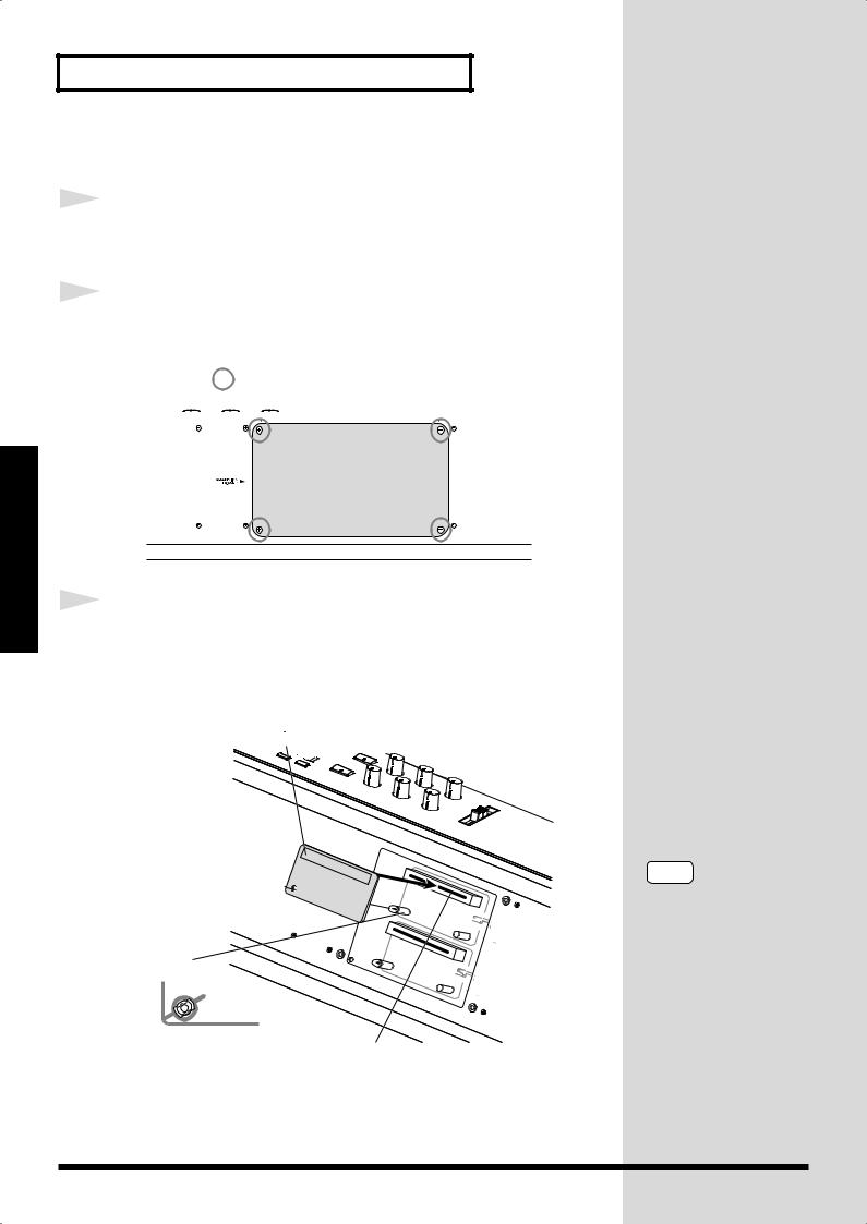
2 |
Refer to the following illustration of the RD-700’s rear panel, |
||
|
|||
|
and remove the screws indicated. Then, remove the cover. |
||
|
fig.Q-02.e |
||
|
|
Screws to be removed |
|
|
|
|
|
|
|
|
|
3 |
Insert the Wave Expansion Board connector into a connector |
|
|
|
for an SRX Series slot (SRX A or SRX B), while simultaneously |
|
inserting the board holders into the holes in the Wave |
|
Expansion Board. |
|
fig.Q-05.e |
|
Wave Expansion Board (SRX series) |
Board holder
Position them as shown |
Connector |
before you install the board. |
NOTE
If the same type of Wave Expansion Board is installed in the SRX A slot and the SRX B slot, it will only be possible to select data from the Wave Expansion Board that was installed in the SRX A slot.
16
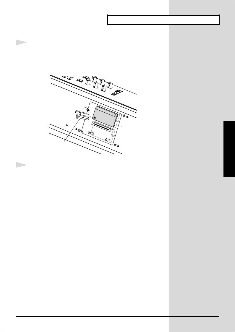
4 |
Use the Installation Tool supplied with the Wave Expansion |
|
|
|
Board to turn the holders in the LOCK direction, so the board |
|
will be fastened in place. |
|
fig.Q-06.e |
LOCK
Installation tool
5 |
Use the screws that you removed in step 2 to fasten the cover |
|
|
|
back in place. |
Getting Ready
Ready Getting
17
Getting Ready
Getting Ready
Checking the Installed Wave Expansion Boards
After installation of the Wave Expansion Boards has been completed, check
to confirm that the installed boards are being recognized correctly.
For instructions on
selecting Wave Expansion
Board Tones, refer to
“Selecting Wave
Expansion Board Tones”
fig.panel
CONTROL
2
1
2
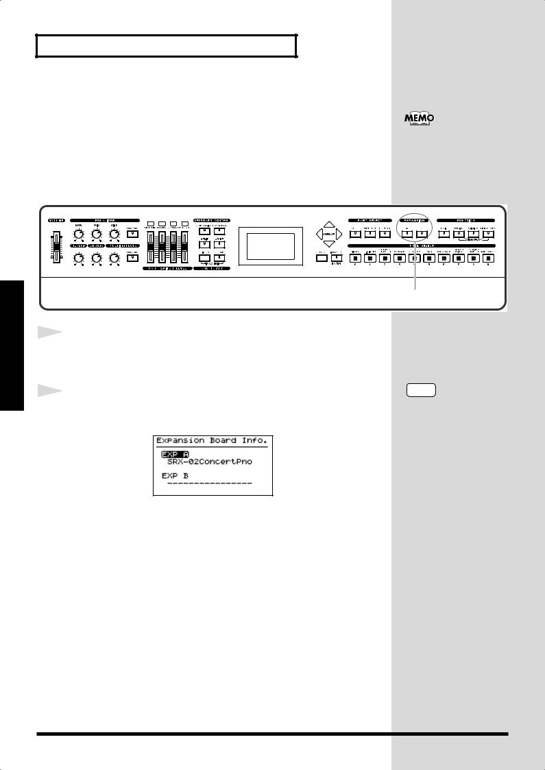
Turn on the power, as described in “Turning On the Power”
(p. 24).
Hold down EXPANSION [A] or [B] for several seconds.
The name of the installed wave expansion board appears in the display.
fig.LCD
The example here depicts what you would see if the SRX-02 “Concert Piano” Wave Expansion Board were installed in the SRX A slot.
By releasing the button, you go back to the previous screen.
NOTE
If “—————-” appears next to the name of the slot in which the board was installed, it may be that the wave expansion board is not being recognized properly. Use the procedure in “Turning Off the Power” (p. 25) to turn the power off, then reinstall the wave expansion board correctly.
18
Installation de la carte d’extension Wave
(French language for Canadian Safety Standard)
Vous pouvez installer jusqu’à 2 cartes d’extension optionnelles dans le RD700.
Ces cartes d’extension mémorisant des données Wave, des morceaux et des ensembles rythmiques, elles vous permettront d’augmenter considérablement le timbre.
Precautions lors de l’installation de la carte d’extension Wave
●Veuillez suivre attentivement les instructions suivantes quand vous manipulez la carte afin d’éviter tout risque d’endommagement des pièces internes par l’électricité statique.
•Toujours toucher un objet métallique relié à la terre (comme un tuyau par exemple) avant de manipuler la carte pour vous décharger de l’électricité statique que vous auriez pu accumuler.
•Lorsque vous manipulez la carte, la tenir par les côtés. Évitez de toucher aux composants ou aux connecteurs.
•Conservez le sachet d’origine dans lequel était la carte lors de l’envoi et remettez la carte dedans si vous devez la ranger ou la transporter.
●Utiliser un tournevis cruciforme correspondant à la taille de la vis (un tournevis numéro 2). En cas d’utilisation d’un tournevis inapproprié, la tête de la vis pourrait être endommagée.
●Pour enlever les vis, tourner le tournevis
dans le sens contraire des aiguilles d’une |
desserrer |
resserrer |
montre. Pour resserrer, tourner dans le |
|
|
sens des aiguilles d’une montre. |
|
|
|
|
●Veillez à ne pas laisser tomber de vis dans le châssis du RD-700.
●Ne pas laisser la plaque arrière détachée. Après avoir installé la ou les carte(s) d’extension, bien remettre la plaque en place.
●Ne pas toucher aux circuits imprimés ou aux connecteurs.
●Veillez à ne pas vous couper les doitgs sur le bord de l’ouverture d’installation.
●Ne jamais forcer lors de l’installation de la carte de circuits imprimés. Si la carte s’ajuste mal au premier essai, enlevez la carte et recommencez l’installation.
●Quand l’installation de la carte de circuits imprimés est terminée, revérifiez si tout est bien installé.
●Toujours éteindre et débrancher l’appareil avant de commencer l’installation de la carte.
●N’installez que les cartes de circuits imprimes spécifiées (SRX Series). Enlevez seulement les vis indiquées.
Installer les cartes d’extension après avoir enlevé la plaque arrière.
Getting Ready
Ready Getting
19
Getting Ready
Getting Ready
Installer les cartes de série SRX
1 |
Avant d’installer une carte d’extension Wave, éteindre tous les |
||
|
|||
|
appareils reliés au RD-700. |
||
2 |
Détacher la plaque arrière en enlevant les vis indiquées sur le |
||
|
|||
|
schéma suivant. |
||
|
fig.Q-02.f |
||
|
|
Vis à enlever |
|
|
|
|
|
|
|
|
|
3 |
Insérer le connecteur de la carte dans un des créneaux pour la |
|
|
|
série SRX (SRX A, SRX B) tout en enfonçant les supports à |
|
carte dans les trous de celle-ci. |
|
fig.Q-05.f |
|
Carte d'extension Wave (serie SRX) |
Support à carte
Avant l’installation, orienter les supports |
Connecteur |
à carte tel qu’indiqué sur le schéma. |
NOTE
Si la même sorte de carte d’extension Wave est installée dans les créneaux SRX A et SRX B, il ne sera possible de sélectionner que les données de la carte d’extension Wave installée dans le créneau SRX A.
20

Getting Ready
4 |
Pour tourner les supports en position LOCK (verrouillé), |
|
|
|
utilisez l’outil d’installation de la carte d’extension fournie à |
|
cet effet. De cette façon, la carte sera bien fixée à sa place. |
|
fig.Q-06.f |
|
LOCK |
Outil d'installation
5 |
Reposez le couvercle en remettant les vis enlevées (comme |
|
|
|
spécifié) à l’étape 2. |
Vérification des cartes d’extension audio aprés installation
Lorsque l’installation des cartes d’extension audio est terminée, procéder à une vérification pour s’assurer que l’ordinateur les identifie correctement.
fig.Q-07
CONTROL
2
1 |
Mettre sous tension de la façon décrite sous “Turning On the |
||||
|
|||||
|
Power” (p. 24). |
||||
2 |
Tenez EXPANSION [A] ou [B] enfoncé pendant plusieurs |
||||
|
|||||
|
secondes. |
||||
|
fig.LCD |
||||
|
|
|
|
|
|
|
|
|
|
|
|
|
|
|
|
|
|
L’exemple montre ce qui serait affiché si la carte d’extension audio SRX-02 “Concert Piano“était installée dans la fente SRX A.
Lorsque vous le relâcherez, vous serez ramené à l'écran précédent.
NOTE
Si “----------------“ est affiché à côté du nom de la fente dans laquelle la carte est installée, il est possible que la carte d’extension audio installée ne soit pas reconnue correctement. Mettre hors tension de la façon décrite sous
“Turning Off the Power”
(p. 25) et réinstaller
correctement la carte
d’extension audio.
Ready Getting
21
Getting Ready
Getting Ready
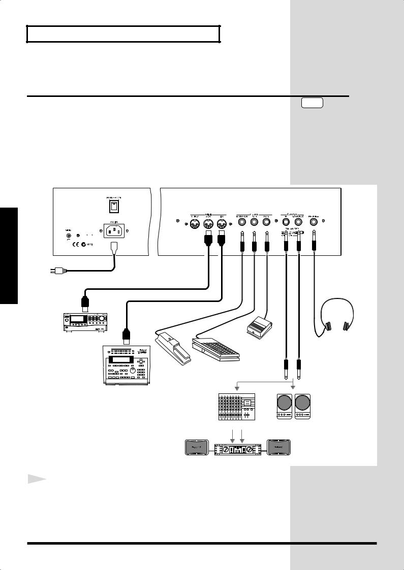
Connecting the RD-700 to External Equipment
The RD-700 is not equipped with an amplifier or speakers. In order to produce sound, you need to hook up audio equipment such as a monitor speaker or a stereo set, or use headphones.
*Audio cables, MIDI cables, headphones, and expression pedals are not included. Consult your Roland dealer if you need to purchase accessories such as these.
fig.00-05.e
to Power outlet
MIDI IN
MIDI sound module etc.
MIDI OUT |
Pedal switch |
|
(DP-2, DP-6 etc.) |
Expression pedal (EV-5) or Pedal switch
NOTE
To prevent malfunction and/or damage to speakers or other devices, always turn down the volume, and turn off the power on all devices before making any connections.
Stereo headphones
MIDI sequencer etc.
Mixer etc. Monitor speakers (powered)
Power amp.
1 |
Before you begin making connections, confirm the following. |
|
Is the volume level of the RD-700 or connected amp turned all the way down?
Is the power to the RD-700 or connected amp turned off?
22
Getting Ready
2 |
NOTE |
|
Connect supplied AC power cable to the RD-700, and plug the |
|
Use Stereo headphones. |
|
other end into an AC power outlet. |
|
NOTE |
3 |
Connect the RD-700 and the external device. |
|
Use audio cables to connect audio equipment, such as an amp or speakers. Use MIDI cables to connect MIDI devices.
If you are using headphones, plug them into the PHONES jack.
Connect pedal switches or expression pedals as necessary.
Use only the specified expression pedal (EV-5; sold separately). By connecting any other expression pedal, you risk causing malfunction and/ or damage to the unit.
Connecting Pedals
Connect the pedal included with the RD-700 to one of the Pedal jacks.
When connected to the Damper jack, the pedal can be used as a damper pedal.
Connecting the pedal to the FC-1 or FC-2 jack allows you to assign a variety of functions to the pedal (p. 73).
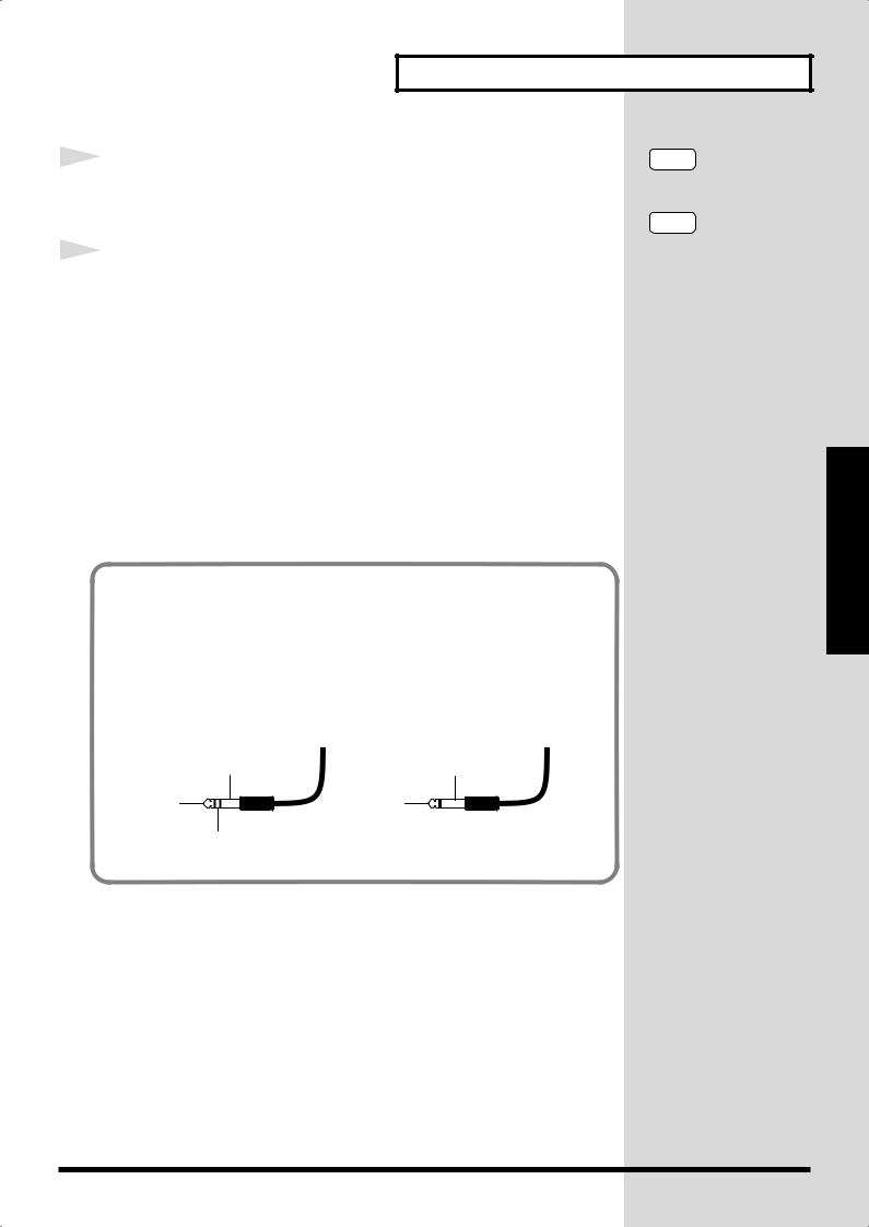
About the Output Jacks
The RD-700’s output jacks are capable of use with either balanced or unbalanced output.
To use balanced output, use a cable with a balanced (TRS type) phone plug. To use unbalance output, use a cable with an unbalanced (TS type) phone plug.
fig.TRS
TRS |
TS |
SLEEVE (Ground) |
SLEEVE (Ground) |
TIP (Hot) |
TIP (Hot) |
RING (Cold) |
|
Ready Getting
23
Getting Ready
Turning the Power On and Off
Once the connections have been completed, turn on power to your various devices in the order specified. By turning on devices in the wrong order, you risk causing malfunction and/or damage to speakers and other devices.
Turning On the Power
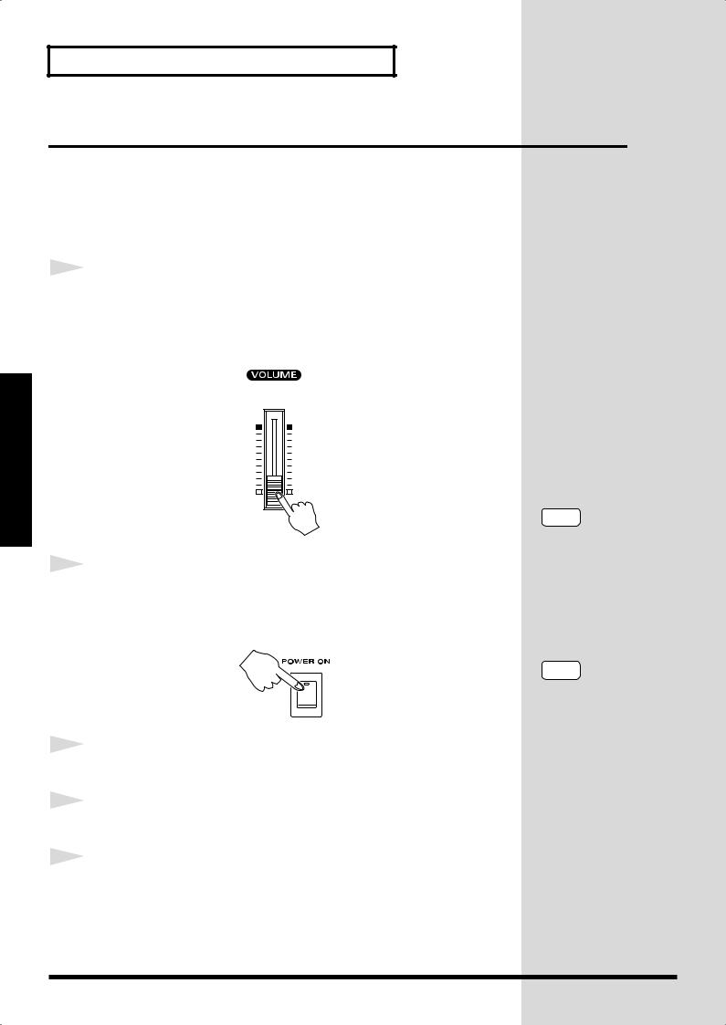
1 |
Before you switch on the power, turn the volume down all the |
|
way by rotating the VOLUME Slider.
Also completely turn down the volume of any connected audio device and other equipment.
fig.00-06
Getting Ready
2 |
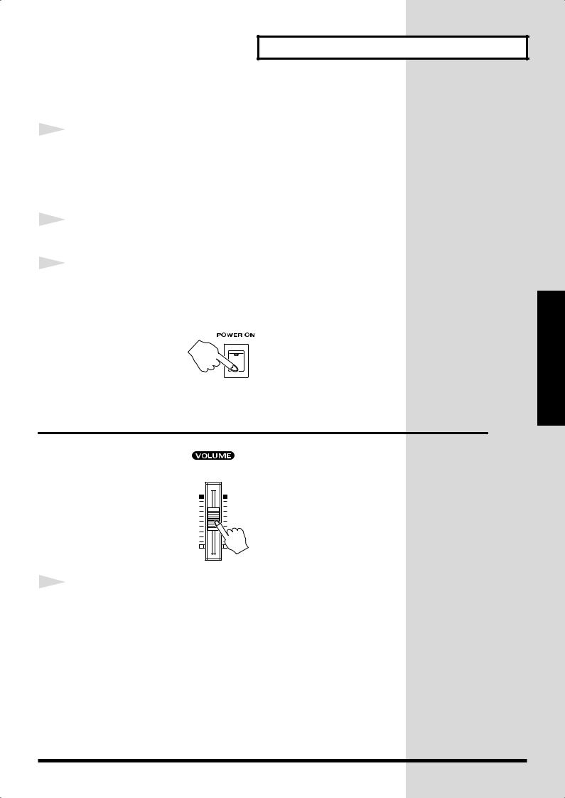
Press the upper portion of the [POWER] switch to turn on the |
|
|
|
power. |
|
The unit is powered up, and the display's backlighting comes on. |
|
fig.00-07 |
3 |
Turn on the power to connected external devices. |
|
|
4 |
Adjust the volume of the connected external device. |
|
|
5 |
Adjust the RD-700’s volume to obtain the proper volume level. |
|
NOTE
To prevent incorrect functioning of the Pitch Bend Lever (p. 48), refrain from touching the lever while the power to the RD700 is turned on.
NOTE
This unit is equipped with a protection circuit. A brief interval (a few seconds) after power up is required before the unit will operate normally.
24
Turning Off the Power
1 |
Before you switch on the power, turn the volume down all the |
|
way by rotating the VOLUME Slider.
Also completely turn down the volume of any connected audio device and other equipment.
2 |
Turn off the power to connected external devices. |
|
|
3 |
Press the lower portion of the [POWER] switch on the back of |
|
|
|
the RD-700. |
|
The power is switched off. |
|
fig.00-07 |
Adjusting the Volume
fig.00-08
1 |
Adjust the volume using the VOLUME slider. |
|
Move the slider up to increase the volume, or down to lower it.
Also adjust the volume of the connected device to an appropriate level.
Getting Ready
Ready Getting
25
Getting Ready
Getting Ready
Restoring the Factory Settings
(Factory Reset)
When using the RD-700 for the first time, start by returning the settings to their factory defaults so that the RD-700 operates as described in the procedures in the owner’s manual.
Notes
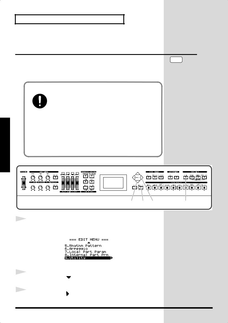
Never turn off the power during Factory Reset (while “Now, Executing” appears in the display).
Turning off the power while Factory Reset is in progress may result in corrupted internal data and may prevent the power from being turned on again. If you have confirmed that the internal data has been lost, or if a similar problem exists, consult the retailer from whom you purchased the instrument, or the nearest Roland Service Center. Note, however, that Roland assumes no liability, including compensation, for consequences arising from any loss of data.
NOTE
Executing this operation deletes the Setup settings (p. 54). If you want to keep any internally stored content, use the “Bulk Dump (Bulk Dump SETUP)” procedure to save the data to an external sequencer (p. 92).
fig.panel
CONTROL
2,4 |
6,7 |
3,5 |
1 |
1 |
Press [EDIT], getting the indicator to light. |
||
|
|||
|
The Edit Menu screen appears. |
||
|
fig.Editmenu2.eps_150 |
||
|
|
|
|
|
|
|
|
2 |
Press CURSOR [ |
] to select “9.Utility.” |
|
||
3 |
Press CURSOR [ |
] to display the Edit screen. |
|
26
4
5
6
7
Getting Ready
fig.utility1.eps_150
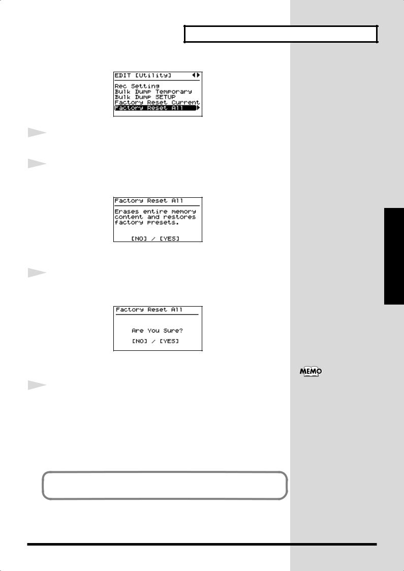
Press CURSOR [  ] to select “Factory Reset All.”
Press CURSOR [  ].
].
A screen like the one shown below appears.
fig.utility1.eps_150
To cancel the Factory Reset, press [DEC/NO].
Press [INC/YES].
The confirmation message appears.
fig.LCD_150
To cancel the Factory Reset, press [DEC/NO].
Press [INC/YES] once again to start the Factory Reset
operation.
During the execution, “Now, Executing” appears in the display.
After the Factory Reset operation is finished, the display will indicate “COMPLETED” and the Tone screen will appear.
After performing a Factory Reset, you may need to readjust the display contrast. When this occur, adjust depth of the display (p. 28).
You can also restore only part of the setting to their factory status. Refer to
“Restoring the settings to the factory condition (Factory Reset)” (p. 94).
Ready Getting
27

Getting Ready
Getting Ready
Adjusting the Display Contrast
(LCD Contrast)
The characters in the display may be difficult to view immediately after turning on the power or after extended use; this may also be because of where and how the display is situated. Follow the steps below to adjust the display’s contrast.
fig.panel
The LCD CONTRAST setting affects the RD-700 as a whole (i.e., is a system setting). This setting remains stored in memory even while the power is off.
CONTROL
2,4 |
5 |
3 |
1,6 |
1 |
Press [EDIT], getting the indicator to light. |
||
|
|||
|
The Edit Menu screen appears. |
||
|
fig.Editmenu1.eps_150 |
||
|
|
|
|
|
|
|
|
2 |
Press CURSOR [ |
] to select “0.System.” |
|
||
3 |
Press CURSOR [ |
] to display the Edit screen. |
|
fig.system1.eps_150
4 |
Press CURSOR [ ] or [ ] to move the cursor to the “LCD |
|
|
|
Contrast” parameter. |
5 |
Press [INC/YES] or [DEC/NO] to select the value (1–10). |
|
The brightness of the display changes as the value is changed. Adjust the contrast so that the display is easy to view.
28
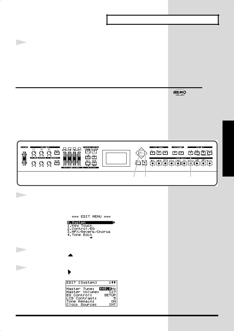
Getting Ready
6 |
Press [EDIT] to make the indicator go dark. |
|
You are returned to the Tone screen.
Tuning to Other Instruments’ Pitches (Master Tune)
For a cleaner ensemble sound while performing with one or more other instruments, ensure that each instrument’s basic pitch is in tune with that of the other instruments. In general, the tuning of an instrument is indicated by the pitch in Hertz (Hz) of the middle “A” note.
This matching of other instruments’ basic reference pitches is called “tuning.”
The Master Tune setting is a system setting that is applied to the entire RD700 (i.e., is a system setting), This setting remains stored in memory even while the power is off.
fig.panel
CONTROL
2 |
3 |
1 |
1 |
Press [EDIT], getting the indicator to light. |
||
|
|||
|
The Edit Menu screen appears. |
||
|
fig.Editmenu1.eps_150 |
||
|
|
|
|
|
|
|
|
2 |
Press CURSOR [ |
] to select “0.System.” |
|
||
3 |
Press CURSOR [ |
] to display the Edit screen. |
|
fig.system1.eps_150
Ready Getting
29

Getting Ready
Getting Ready
CONTROL
4
5
6
4 5
Press CURSOR [  ] to move the cursor to the “Master Tune” parameter.
Press [INC/YES] or [DEC/NO] to select the value (415.3– 440.0–466.2).
Press [EDIT] to make the indicator go dark.
You are returned to the Tone screen.
6
For faster value increases, keep [INC/YES] pressed down and press [DEC/ NO]. For decreasing value faster, keep [DEC/NO] pressed down and press [INC/YES].
30
Loading...