


Hardware Reference, Installation, and Troubleshooting Manual D2-3340-1
GV3000 AC Power Modules
Version 5.0
Important User Information
Solid-state equipment has operational characteristics differing from those of electromechanical equipment. Safety Guidelines for the Application, Installation and Maintenance of Solid State Controls (publication SGI-1.1 available from your local Rockwell Automation sales office or online at http://www.rockwellautomation.com/literature/) describes some important differences between solid-state equipment and hard-wired electromechanical devices. Because of this difference, and also because of the wide variety of uses for solid-state equipment, all persons responsible for applying this equipment must satisfy themselves that each intended application of this equipment is acceptable.
In no event will Rockwell Automation, Inc. be responsible or liable for indirect or consequential damages resulting from the use or application of this equipment.
The examples and diagrams in this manual are included solely for illustrative purposes. Because of the many variables and requirements associated with any particular installation, Rockwell Automation, Inc. cannot assume responsibility or liability for actual use based on the examples and diagrams.
No patent liability is assumed by Rockwell Automation, Inc. with respect to use of information, circuits, equipment, or software described in this manual.
Reproduction of the contents of this manual, in whole or in part, without written permission of Rockwell Automation, Inc., is prohibited.
Throughout this manual, when necessary, we use notes to make you aware of safety considerations.
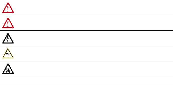
WARNING: Identifies information about practices or circumstances that can cause an explosion in a hazardous environment, which may lead to personal injury or death, property damage, or economic loss.
ATTENTION: Identifies information about practices or circumstances that can lead to personal injury or death, property damage, or economic loss. Attentions help you identify a hazard, avoid a hazard, and recognize the consequence.
SHOCK HAZARD: Labels may be on or inside the equipment, for example, a drive or motor, to alert people that dangerous voltage may be present.
BURN HAZARD: Labels may be on or inside the equipment, for example, a drive or motor, to alert people that surfaces may reach dangerous temperatures.
ARC FLASH HAZARD: Labels may be on or inside the equipment, for example, a motor control center, to alert people to potential Arc Flash. Arc Flash will cause severe injury or death. Wear proper Personal Protective Equipment (PPE). Follow ALL Regulatory requirements for safe work practices and for Personal Protective Equipment (PPE).
IMPORTANT Identifies information that is critical for successful application and understanding of the product.
Allen-Bradley, Rockwell Software, Rockwell Automation, and TechConnect are trademarks of Rockwell Automation, Inc.
Trademarks not belonging to Rockwell Automation are property of their respective companies.

Document Update
Document Update
Electronic Motor Overload
Protection
This product does not offer speed-sensitive overload protection, thermal memory retention or provisions to act upon motor over-temperature sensing in motors. If such protection is needed in the end-use product, it needs to be provided by additional means.
1

Document Update
Notes:
2

Summary of Changes
The information below summarizes the changes made to this manual since its last release (December 1995).
Description of Changes |
Page |
|
|
Added Document Update. |
After manual |
|
front cover |
|
|
Deleted the following statement: ‘The Motor Overload Enable parameter (P.040) can |
6-1 |
be used in place of the electronic thermal overload relays in single motor |
|
applications’. |
|
|
|

soc-ii Summary of Changes
Notes:

Manufacturer's Declaration
Manufacturer:
Reliance Electric Industrial Co.
24701 Euclid Avenue
Cleveland, Ohio 44117 - USA
declares that the product:
GV3000, A'C Speed Controller for Electric Motors
is intended to be incorporated into machinery or to be assembled with other machinery to constitute machinery covered by Directive 89/392/EEC, as amended;
and that
the following harmonized standards have been applied:
EN 60204'1: Electrical equipment of industrial machines - Part 1: General Requirements
and furthermore declares that the product covered by this Declaration must not be put into service until the machinery into which it is to be incorporated or of which it is a component has been found and declared to be in conformity with the provisions of Directive 89/392/EEC and with national implementing legislation, i.e., as a whole, including the product referred to in this Declaration.
Authorized Representative of the Company:
Place: Reliance Electric Industrial Co., Cleveland, Ohio 44117, USA
Date: December 1, 1995
Signature:
Name: Charles Janki
Position: Product Development Safety Engineer
Table of Contents
1.0 Becoming Familiar with the Manual . . . . . . . . . . . . . . . . . . . . . . . . . . . . . . . . . . . . . . . . . . . . . . . . . . 1 1
1.1 Finding Information . . . . . . . . . . . . . . . . . . . . . . . . . . . . . . . . . . . . . . . . . . . . . . . . . . . . . . . . . . . . . . . 1 1 1.2 Assumptions About the Audience . . . . . . . . . . . . . . . . . . . . . . . . . . . . . . . . . . . . . . . . . . . . . . . . . . 1 2 1.3 Taking Safety Precautions . . . . . . . . . . . . . . . . . . . . . . . . . . . . . . . . . . . . . . . . . . . . . . . . . . . . . . . . . 1 2 1.4 Understanding Terms Used in this Manual . . . . . . . . . . . . . . . . . . . . . . . . . . . . . . . . . . . . . . . . . . 1 2 1.5 If You Want to Know More . . . . . . . . . . . . . . . . . . . . . . . . . . . . . . . . . . . . . . . . . . . . . . . . . . . . . . . . . 1 2 1.6 Getting Assistance from Reliance Electric . . . . . . . . . . . . . . . . . . . . . . . . . . . . . . . . . . . . . . . . . . . 1 2
2.0 About the Drive . . . . . . . . . . . . . . . . . . . . . . . . . . . . . . . . . . . . . . . . . . . . . . . . . . . . . . . . . . . . . . . . . . . . . 2 1
2.1 Identifying the Drive by Model Number . . . . . . . . . . . . . . . . . . . . . . . . . . . . . . . . . . . . . . . . . . . . . 2 1 2.2 NEMA Enclosures . . . . . . . . . . . . . . . . . . . . . . . . . . . . . . . . . . . . . . . . . . . . . . . . . . . . . . . . . . . . . . . . 2 2 2.3 1 25 HP GV3000 Drive Components and Locations . . . . . . . . . . . . . . . . . . . . . . . . . . . . . . . . . . . 2 3 2.4 25 60 HP GV3000 Drive Components and Locations . . . . . . . . . . . . . . . . . . . . . . . . . . . . . . . . . 2 6 2.5 60 100 HP GV3000 Drive Components and Locations . . . . . . . . . . . . . . . . . . . . . . . . . . . . . . . . 2 7 2.6 100 150 HP GV3000 Drive Components and Locations . . . . . . . . . . . . . . . . . . . . . . . . . . . . . . . 2 8 2.7 Regulator Board Description . . . . . . . . . . . . . . . . . . . . . . . . . . . . . . . . . . . . . . . . . . . . . . . . . . . . . . 2 9
2.7.1 Jumper Locations and Settings . . . . . . . . . . . . . . . . . . . . . . . . . . . . . . . . . . . . . . . . . . . . . . . 2 12 2.7.1.1 Analog Input Speed Reference Jumper . . . . . . . . . . . . . . . . . . . . . . . . . . . . . . . . 2 12 2.7.1.2 Analog Output Jumper . . . . . . . . . . . . . . . . . . . . . . . . . . . . . . . . . . . . . . . . . . . . . . . 2 13 2.7.2 Wiring the Terminal Strip . . . . . . . . . . . . . . . . . . . . . . . . . . . . . . . . . . . . . . . . . . . . . . . . . . . . . 2 14
2.7.3 RS 232 Communication Port . . . . . . . . . . . . . . . . . . . . . . . . . . . . . . . . . . . . . . . . . . . . . . . . . 2 15 2.7.4 Option Board Connector . . . . . . . . . . . . . . . . . . . . . . . . . . . . . . . . . . . . . . . . . . . . . . . . . . . . . 2 15 2.7.5 Operator Interface Module Connector . . . . . . . . . . . . . . . . . . . . . . . . . . . . . . . . . . . . . . . . . 2 15 2.7.6 Keypad/Display . . . . . . . . . . . . . . . . . . . . . . . . . . . . . . . . . . . . . . . . . . . . . . . . . . . . . . . . . . . . . 2 15 2.8 Drive Kit Options . . . . . . . . . . . . . . . . . . . . . . . . . . . . . . . . . . . . . . . . . . . . . . . . . . . . . . . . . . . . . . . . . 2 16
3.0 Planning Before Installing . . . . . . . . . . . . . . . . . . . . . . . . . . . . . . . . . . . . . . . . . . . . . . . . . . . . . . . . . . . 3 1
3.1 Requirements for the Installation Site . . . . . . . . . . . . . . . . . . . . . . . . . . . . . . . . . . . . . . . . . . . . . . . 3 1 3.1.1 Making Sure Environmental Conditions are Met . . . . . . . . . . . . . . . . . . . . . . . . . . . . . . . . 3 1 3.1.2 Determining Total Area Required Based on Drive Dimensions . . . . . . . . . . . . . . . . . . . . 3 2 3.1.3 Verifying the Site Provides for Recommended Air Flow Clearances . . . . . . . . . . . . . . . . 3 4 3.1.4 Verifying Power Module Input Ratings Match Supplied Power . . . . . . . . . . . . . . . . . . . . 3 5
3.2 Wiring Requirements for the Drive . . . . . . . . . . . . . . . . . . . . . . . . . . . . . . . . . . . . . . . . . . . . . . . . . . 3 5 3.2.1 Meeting Terminal Strip Input and Output Specifications . . . . . . . . . . . . . . . . . . . . . . . . . . 3 5 3.2.2 Determining Wire Size Requirements . . . . . . . . . . . . . . . . . . . . . . . . . . . . . . . . . . . . . . . . . . 3 5 3.2.2.1 Conduit Entry Opening Sizes . . . . . . . . . . . . . . . . . . . . . . . . . . . . . . . . . . . . . . . . . . 3 5 3.2.2.2 Recommended Power Wire Sizes . . . . . . . . . . . . . . . . . . . . . . . . . . . . . . . . . . . . . 3 5 3.2.2.3 Recommended Control and Signal Wire Sizes . . . . . . . . . . . . . . . . . . . . . . . . . . 3 6 3.2.2.4 Recommended Motor Lead Lengths . . . . . . . . . . . . . . . . . . . . . . . . . . . . . . . . . . . 3 6 3.2.2.5 Recommended Serial Communication Cable Lengths . . . . . . . . . . . . . . . . . . . . 3 7 3.2.3 Selecting Input Line Branch Circuit Fuses . . . . . . . . . . . . . . . . . . . . . . . . . . . . . . . . . . . . . . 3 7
3.2.4 Meeting Pulse Tachometer Specifications (Vector Regulation Only) . . . . . . . . . . . . . . . . 3 8 3.2.5 Verifying Power Module Output Current Rating is Greater Than Motor Full
Load Amps . . . . . . . . . . . . . . . . . . . . . . . . . . . . . . . . . . . . . . . . . . . . . . . . . . . . . . . . . . . . . . . . 3 8
I
4.0 Mounting the Drive, Grounding, and Finding Wire Routing Locations . . . . . . . . . . . . . . . . . . . 4 1
4.1 Mounting the Drive . . . . . . . . . . . . . . . . . . . . . . . . . . . . . . . . . . . . . . . . . . . . . . . . . . . . . . . . . . . . . . . 4 1 4.1.1 Verifying the Drive's Watts Loss Rating . . . . . . . . . . . . . . . . . . . . . . . . . . . . . . . . . . . . . . . . 4 1 4.2 Routing Input, Motor Output, Ground, and Control Wiring for the Drive . . . . . . . . . . . . . . . . . 4 1 4.3 Grounding the Drive . . . . . . . . . . . . . . . . . . . . . . . . . . . . . . . . . . . . . . . . . . . . . . . . . . . . . . . . . . . . . . 4 8
5.0 Installing Input Power Wiring . . . . . . . . . . . . . . . . . . . . . . . . . . . . . . . . . . . . . . . . . . . . . . . . . . . . . . . . 5 1
5.1 Installing Transformers and Reactors (Optional) . . . . . . . . . . . . . . . . . . . . . . . . . . . . . . . . . . . . . . 5 1 5.2 Installing Fuses for Branch Circuit Protection . . . . . . . . . . . . . . . . . . . . . . . . . . . . . . . . . . . . . . . . 5 1 5.3 Installing a Required External/Separate Input Disconnect . . . . . . . . . . . . . . . . . . . . . . . . . . . . . 5 4 5.4 Installing Power Wiring from the A C Input Line to the Drive's Power Terminals . . . . . . . . . . . 5 4 5.5 Installing Power Wiring from an External D C Bus to the Drive's Internal D C Bus
Terminals . . . . . . . . . . . . . . . . . . . . . . . . . . . . . . . . . . . . . . . . . . . . . . . . . . . . . . . . . . . . . . . . . . . . . . . 5 5
6.0 Installing Output Power Wiring . . . . . . . . . . . . . . . . . . . . . . . . . . . . . . . . . . . . . . . . . . . . . . . . . . . . . . |
6 1 |
6.1 Installing Output Contactors (Optional) . . . . . . . . . . . . . . . . . . . . . . . . . . . . . . . . . . . . . . . . . . . . . 6 1 6.2 Installing Mechanical Motor Overload Protection (Optional) . . . . . . . . . . . . . . . . . . . . . . . . . . . . 6 1 6.3 Installing Output Wiring from the Drive Output Terminals to the Motor . . . . . . . . . . . . . . . . . . . 6 1
7.0 Wiring the Regulator Board Terminal Strip . . . . . . . . . . . . . . . . . . . . . . . . . . . . . . . . . . . . . . . . . . . . 7 1
7.1 Stopping the Drive . . . . . . . . . . . . . . . . . . . . . . . . . . . . . . . . . . . . . . . . . . . . . . . . . . . . . . . . . . . . . . . 7 5 7.1.1 Compliance with EN 60204 1: 1992 . . . . . . . . . . . . . . . . . . . . . . . . . . . . . . . . . . . . . . . . . . . 7 5 7.2 Wiring the Speed Feedback Device (Vector Regulation Only) . . . . . . . . . . . . . . . . . . . . . . . . . . 7 5 7.3 Wiring the Signal and Control I/O . . . . . . . . . . . . . . . . . . . . . . . . . . . . . . . . . . . . . . . . . . . . . . . . . . 7 7
8.0 Completing the Installation . . . . . . . . . . . . . . . . . . . . . . . . . . . . . . . . . . . . . . . . . . . . . . . . . . . . . . . . . . 8 1
8.1 Checking the Installation . . . . . . . . . . . . . . . . . . . . . . . . . . . . . . . . . . . . . . . . . . . . . . . . . . . . . . . . . . 8 1 8.2 Installing the Cover for NEMA 4X/12 Drives . . . . . . . . . . . . . . . . . . . . . . . . . . . . . . . . . . . . . . . . . . 8 2 8.3 Powering Up After Installation is Complete . . . . . . . . . . . . . . . . . . . . . . . . . . . . . . . . . . . . . . . . . . 8 2
9.0 Troubleshooting the Drive . . . . . . . . . . . . . . . . . . . . . . . . . . . . . . . . . . . . . . . . . . . . . . . . . . . . . . . . . . . 9 1
9.1 Test Equipment Needed to Troubleshoot . . . . . . . . . . . . . . . . . . . . . . . . . . . . . . . . . . . . . . . . . . . . 9 1 9.2 Drive Alarms and Faults . . . . . . . . . . . . . . . . . . . . . . . . . . . . . . . . . . . . . . . . . . . . . . . . . . . . . . . . . . . 9 1 9.3 Verifying That D C Bus Capacitors are Discharged . . . . . . . . . . . . . . . . . . . . . . . . . . . . . . . . . . . 9 1 9.4 Checking Out the Power Modules with Input Power Off . . . . . . . . . . . . . . . . . . . . . . . . . . . . . . . 9 6 9.5 Replacement Parts . . . . . . . . . . . . . . . . . . . . . . . . . . . . . . . . . . . . . . . . . . . . . . . . . . . . . . . . . . . . . . . 9 8
II
Appendices
Appendix A
Technical Specifications . . . . . . . . . . . . . . . . . . . . . . . . . . . . . . . . . . . . . . . . . . . . . . . . . . . . . . . . . . . . . . . . A 1
Appendix B
Drive Regulation Overview . . . . . . . . . . . . . . . . . . . . . . . . . . . . . . . . . . . . . . . . . . . . . . . . . . . . . . . . . . . . . . B 1
Appendix C
Compliance with EN 60204 1: 1992 . . . . . . . . . . . . . . . . . . . . . . . . . . . . . . . . . . . . . . . . . . . . . . . . . . . . . . C 1
Index . . . . . . . . . . . . . . . . . . . . . . . . . . . . . . . . . . . . . . . . . . . . . . . . . . . . . . . . . . . . . . . . . . . . . . . . . . . . . . . . . . Index 1
III
List of Figures
Figure 2.1 Identifying the Drive Model Number . . . . . . . . . . . . . . . . . . . . . . . . . . . . . . . . . . . . . . . . . . . . . . . . 2 1 Figure 2.2 1 5 HP Drive Components and Locations . . . . . . . . . . . . . . . . . . . . . . . . . . . . . . . . . . . . . . . . . . . 2 3 Figure 2.3 7.5 10 HP Drive Components and Locations . . . . . . . . . . . . . . . . . . . . . . . . . . . . . . . . . . . . . . . . 2 4 Figure 2.4 15 25 HP Drive Components and Locations . . . . . . . . . . . . . . . . . . . . . . . . . . . . . . . . . . . . . . . . . 2 5 Figure 2.5 25 60 HP Drive Components and Locations . . . . . . . . . . . . . . . . . . . . . . . . . . . . . . . . . . . . . . . . . 2 6 Figure 2.6 60 100 HP Drive Components and Locations . . . . . . . . . . . . . . . . . . . . . . . . . . . . . . . . . . . . . . . . 2 7 Figure 2.7 100 150 HP Drive Components and Locations . . . . . . . . . . . . . . . . . . . . . . . . . . . . . . . . . . . . . . 2 8 Figure 2.8 1 60 HP Regulator Board Components and Locations . . . . . . . . . . . . . . . . . . . . . . . . . . . . . . . . 2 10 Figure 2.9 60 150 HP Regulator Board Components and Locations . . . . . . . . . . . . . . . . . . . . . . . . . . . . . 2 11 Figure 2.10 Jumper J4 Settings for Analog Input Speed Reference . . . . . . . . . . . . . . . . . . . . . . . . . . . . . . 2 12 Figure 2.11 Jumper J17 Settings for Analog Outputs . . . . . . . . . . . . . . . . . . . . . . . . . . . . . . . . . . . . . . . . . . 2 13 Figure 2.12 Typical Terminal Strip Connections . . . . . . . . . . . . . . . . . . . . . . . . . . . . . . . . . . . . . . . . . . . . . . . 2 14 Figure 2.13 Keypad/Display . . . . . . . . . . . . . . . . . . . . . . . . . . . . . . . . . . . . . . . . . . . . . . . . . . . . . . . . . . . . . . . . 2 15
Figure 3.1 Drive Dimensions . . . . . . . . . . . . . . . . . . . . . . . . . . . . . . . . . . . . . . . . . . . . . . . . . . . . . . . . . . . . . . . . 3 3 Figure 3.2 Recommended Air Flow Clearances . . . . . . . . . . . . . . . . . . . . . . . . . . . . . . . . . . . . . . . . . . . . . . . 3 4 Figure 3.3 Single and Multiple Motor Lead Lengths . . . . . . . . . . . . . . . . . . . . . . . . . . . . . . . . . . . . . . . . . . . . 3 7
Figure 4.1 Wire Routing Locations for 1 5 HP Drives . . . . . . . . . . . . . . . . . . . . . . . . . . . . . . . . . . . . . . . . . . . 4 2 Figure 4.2 Wire Routing Locations for 7.5 10 HP Drives . . . . . . . . . . . . . . . . . . . . . . . . . . . . . . . . . . . . . . . . 4 3 Figure 4.3 Wire Routing Locations for 15 25 HP Drives . . . . . . . . . . . . . . . . . . . . . . . . . . . . . . . . . . . . . . . . . 4 4 Figure 4.4 Wire Routing Locations for 25 60 HP Drives . . . . . . . . . . . . . . . . . . . . . . . . . . . . . . . . . . . . . . . . . 4 5 Figure 4.5 Wire Routing Locations for 60 100 HP Drives . . . . . . . . . . . . . . . . . . . . . . . . . . . . . . . . . . . . . . . . 4 6 Figure 4.6 Wire Routing Locations for 100 150 HP Drives . . . . . . . . . . . . . . . . . . . . . . . . . . . . . . . . . . . . . . . 4 7
Figure 5.1 Typical A C Input Electrical Connections . . . . . . . . . . . . . . . . . . . . . . . . . . . . . . . . . . . . . . . . . . . . 5 2 Figure 5.2 Typical D C Bus Electrical Connections . . . . . . . . . . . . . . . . . . . . . . . . . . . . . . . . . . . . . . . . . . . . . 5 3
Figure 7.1 Two Wire Start/Stop Sample Control Wiring . . . . . . . . . . . . . . . . . . . . . . . . . . . . . . . . . . . . . . . . . 7 3 Figure 7.2 Three Wire Start/Stop Sample Control Wiring . . . . . . . . . . . . . . . . . . . . . . . . . . . . . . . . . . . . . . . 7 4 Figure 7.3 Wiring Connections for the Speed Feedback Device . . . . . . . . . . . . . . . . . . . . . . . . . . . . . . . . . 7 6
Figure 9.1 D C Bus Voltage Terminals (1 25 HP Drives) . . . . . . . . . . . . . . . . . . . . . . . . . . . . . . . . . . . . . . . . 9 2 Figure 9.2 D C Bus Voltage Terminals (25 60 HP Drives) . . . . . . . . . . . . . . . . . . . . . . . . . . . . . . . . . . . . . . . 9 3 Figure 9.3 D C Bus Voltage Terminals (60 100 HP Drives) . . . . . . . . . . . . . . . . . . . . . . . . . . . . . . . . . . . . . . 9 4 Figure 9.4 D C Bus Voltage Terminals (100 150 HP Drives) . . . . . . . . . . . . . . . . . . . . . . . . . . . . . . . . . . . . . 9 5
Figure B.1 Volts/Hertz Regulation Block Diagram . . . . . . . . . . . . . . . . . . . . . . . . . . . . . . . . . . . . . . . . . . . . . . B 2 Figure B.2 Vector Regulation Block Diagram . . . . . . . . . . . . . . . . . . . . . . . . . . . . . . . . . . . . . . . . . . . . . . . . . . B 3
IV
List of Tables
Table 2.1 |
Power and NEMA Enclosure Ratings . . . . . . . . . . . . . . . . . . . . . . . . . . . . . . . . . . . . . . . . . . . . . . . |
2 2 |
Table 2.2 |
Available Kits and Options . . . . . . . . . . . . . . . . . . . . . . . . . . . . . . . . . . . . . . . . . . . . . . . . . . . . . . . . . |
2 16 |
Table 3.1 |
Ambient Conditions . . . . . . . . . . . . . . . . . . . . . . . . . . . . . . . . . . . . . . . . . . . . . . . . . . . . . . . . . . . . . . |
3 1 |
Table 3.2 |
Drive Dimensions and Weights . . . . . . . . . . . . . . . . . . . . . . . . . . . . . . . . . . . . . . . . . . . . . . . . . . . . . |
3 2 |
Table 3.3 |
Recommended Power Wire Sizes for 1 10 HP Drives . . . . . . . . . . . . . . . . . . . . . . . . . . . . . . . . . . |
3 5 |
Table 3.4 |
Recommended Power Wire Sizes for 15 25 HP Drives . . . . . . . . . . . . . . . . . . . . . . . . . . . . . . . . |
3 5 |
Table 3.5 |
Recommended Power Wire Sizes for 25 60 HP Drives . . . . . . . . . . . . . . . . . . . . . . . . . . . . . . . . |
3 6 |
Table 3.6 |
Recommended Power Wire Sizes for 60 100 HP Drives . . . . . . . . . . . . . . . . . . . . . . . . . . . . . . . |
3 6 |
Table 3.7 |
Recommended Power Wire Sizes for 100 150 HP Drives . . . . . . . . . . . . . . . . . . . . . . . . . . . . . . |
3 6 |
Table 3.8 |
Recommended Terminal Strip Wire Sizes . . . . . . . . . . . . . . . . . . . . . . . . . . . . . . . . . . . . . . . . . . . . |
3 6 |
Table 3.9 |
A C Input Line Fuse Selection Values . . . . . . . . . . . . . . . . . . . . . . . . . . . . . . . . . . . . . . . . . . . . . . . |
3 8 |
Table 5.1 Terminal Tightening Torques . . . . . . . . . . . . . . . . . . . . . . . . . . . . . . . . . . . . . . . . . . . . . . . . . . . . . . . |
5 4 |
|
Table 7.1 |
Wiring Signal and Control I/O to the Terminal Strip . . . . . . . . . . . . . . . . . . . . . . . . . . . . . . . . . . . |
7 7 |
Table 9.1 |
Resistance Checks . . . . . . . . . . . . . . . . . . . . . . . . . . . . . . . . . . . . . . . . . . . . . . . . . . . . . . . . . . . . . . . |
9 6 |
Table 9.2 |
1 5 HP Drive Replacement Parts . . . . . . . . . . . . . . . . . . . . . . . . . . . . . . . . . . . . . . . . . . . . . . . . . . . |
9 8 |
Table 9.3 |
7.5 10 HP Drive Replacement Parts . . . . . . . . . . . . . . . . . . . . . . . . . . . . . . . . . . . . . . . . . . . . . . . . . |
9 8 |
Table 9.4 |
15 25 HP Drive Replacement Parts . . . . . . . . . . . . . . . . . . . . . . . . . . . . . . . . . . . . . . . . . . . . . . . . . |
9 9 |
Table 9.5 |
25 60 HP Drive Replacement Parts . . . . . . . . . . . . . . . . . . . . . . . . . . . . . . . . . . . . . . . . . . . . . . . . . |
9 10 |
Table 9.6 |
60 100 HP Drive Replacement Parts . . . . . . . . . . . . . . . . . . . . . . . . . . . . . . . . . . . . . . . . . . . . . . . . |
9 11 |
Table 9.7 |
100 150 HP Drive Replacement Parts . . . . . . . . . . . . . . . . . . . . . . . . . . . . . . . . . . . . . . . . . . . . . . . |
9 12 |
Table A.1 Service Conditions . . . . . . . . . . . . . . . . . . . . . . . . . . . . . . . . . . . . . . . . . . . . . . . . . . . . . . . . . . . . . . . |
A 1 |
|
Table A.2 |
Ambient Conditions . . . . . . . . . . . . . . . . . . . . . . . . . . . . . . . . . . . . . . . . . . . . . . . . . . . . . . . . . . . . . . . |
A 1 |
Table A.3 |
Terminal Strip Input Specifications . . . . . . . . . . . . . . . . . . . . . . . . . . . . . . . . . . . . . . . . . . . . . . . . . . |
A 2 |
Table A.4 |
Terminal Strip Output Specifications . . . . . . . . . . . . . . . . . . . . . . . . . . . . . . . . . . . . . . . . . . . . . . . . |
A 2 |
Table A.5 |
RS 232 Specifications . . . . . . . . . . . . . . . . . . . . . . . . . . . . . . . . . . . . . . . . . . . . . . . . . . . . . . . . . . . . . |
A 2 |
Table A.6 |
Speed Feedback Device Specifications (Vector Regulation Only) . . . . . . . . . . . . . . . . . . . . . . . |
A 2 |
Table A.7 |
Input Signal Response Times (Worst Case) . . . . . . . . . . . . . . . . . . . . . . . . . . . . . . . . . . . . . . . . . . |
A 3 |
V
1.0 BECOMING FAMILIAR WITH THE MANUAL
This chapter provides help in finding information in the manual and describes the intended audience. Also included are references to other related publications and instructions on receiving assistance from Reliance Electric.
1.1Finding Information
This instruction manual describes the GV3000 drive's Power Module and regulator hardware. It does not cover the GV3000 software. For additional software information, refer to the GV3000 A C General Purpose (V/Hz) and Vector Duty Drive Software Start Up and Reference Manual (D2 3339).
As an aid in finding information in this manual, each chapter is briefly described below:
D Chapter 1 Becoming Familiar with the Manual
Provides information on how the manual is organized and where to find additional information.
D Chapter 2 About the Drive
Identifies drive components and shows their locations.
D Chapter 3 Planning Before Installing
Presents information that must be considered when planning a drive installation.
D Chapter 4 Mounting the Drive, Grounding, and Finding Wire Routing Locations
Describes how to mount the drive and properly ground it.
D Chapter 5 Installing Input Power Wiring
Describes incoming A C and D C line components and how to properly connect them.
D Chapter 6 Installing A C Output Power Wiring
Describes output A C line components and how to properly connect them to the motor.
D Chapter 7 Wiring the Regulator Board Terminal Strip
Provides information on the I/O wiring that connects to the terminal strip on the
Regulator board.
D Chapter 8 Completing the Installation
Provides instructions on how to perform a final check of the installation before power is applied.
D Chapter 9 Troubleshooting the Drive
Describes the equipment that is needed to troubleshoot the drive and how to measure D C bus voltage. Replacement part lists are also provided.
D Appendix A Technical Specifications
Lists drive specifications in table form.
D Appendix B Drive Regulation Overview
Briefly describes volts/hertz and vector regulation.
D Appendix C Compliance with EN 60204 1: 1992
Lists the sections of standard EN 60204 1: 1992 that the GV3000 drive complies with.
1 1

1.2Assumptions About the Audience
This manual is intended for qualified electrical personnel. It is task oriented and is organized according to a logical progression of steps to be followed to install and troubleshoot the drive.
1.3Taking Safety Precautions
Dangers, warnings, and cautions are used in this manual to point out potential problem areas. All three types of precautions are enclosed in a box to call attention to them.
DANGER
A DANGER ALERTS A PERSON OF A CONDITION WHICH COULD RESULT IN SEVERE BODILY INJURY OR LOSS OF LIFE.
WARNING
A WARNING ALERTS A PERSON OF A CONDITION WHICH COULD RESULT IN POTENTIAL BODILY INJURY IF PROCEDURES ARE NOT FOLLOWED.
CAUTION: A caution alerts a person of a condition which could result in damage to, or destruction of the equipment.
1.4Understanding Terms Used in this Manual
The following terms are defined according to the way they are used in this manual:
DGV3000 drives will typically be referenced by horsepower. If additional clarity is required, drive model numbers will also be included.
DParameters will be referenced either as parameter (P.030) or Elapsed Time Meter Reset (P.030).
1.5If You Want to Know More
Refer to the following related publications as necessary for more information:
D D2 3339 GV3000 A C General Purpose (V/Hz) and Vector Duty Drive Software Start Up and Reference Manual
DD2 3291 Snubber Resistor Braking Kit
DD2 3305 Motor Encoder Cable Kit
DD2 3308 AutoMax Network Communication Board
DD2 3348 Control and Configuration Software (CS3000)
DD2 3341 Remote Meter Interface
DD2 3342 Operator Interface Module
1.6Getting Assistance from Reliance Electric
If you have any questions or problems with the products described in this instruction manual, contact your local Reliance Electric sales office. For technical assistance, call 1 800 RELIANCE.
1 2
2.0 ABOUT THE DRIVE
This chapter describes how to identify the drive using the model number matrix and illustrates the differences between the NEMA enclosures. Major components of each drive group are also shown.
The GV3000 A C drive is a PWM drive that provides vector and general purpose (volts/hertz or V/Hz) regulation for a wide range of applications.
Using vector regulation, the drive can provide high dynamic response, maintain full rated motor torque to zero speed, and precisely control motor speed in both directions using pulse tachometer feedback.
Using general purpose (volts/hertz) regulation, the drive is suited for a broad range of applications requiring adjustable speed control of motors.
2.1Identifying the Drive by Model Number
Each GV3000 A C drive can be identified by its model number. See figure 2.1. This number appears on the shipping label and on the drive's nameplate. The drive's model number includes the Power Module and the regulator. Drive power ratings are provided in table 2.1.
NNN A N N NN
Horsepower Ratings
V = v 50 HP
GV3000 R = u 50 HP
G = V/Hz Only
Voltage
2 = 200*230V
4 = 380*460V
Enclosure
1 = NEMA 1
2 = NEMA 12 Only
4 = NEMA 4X (Indoor Only) or NEMA 12
Regulator Version
5.0 = Vector and V/Hz Regulator
Figure 2.1 Identifying the Drive Model Number
2 1
Table 2.1 Power and NEMA Enclosure Ratings
|
Selected |
Input |
|
|
|
Output |
Power |
Model |
Regulation* and |
Voltage |
NEMA |
Input |
Input |
Amps |
Loss Watts |
Number |
Horsepower Rating |
(+/- 10%) |
Rating |
KVA |
Amps |
at 8 kHz |
(Full Load) |
|
|
|
|
|
|
|
|
1V4150 |
V/Hz or Vector |
380-460 VAC |
1 |
2.0 |
2.5 |
2.1 |
60 |
1V4450 |
(1 HP) |
|
4X/12 |
|
|
|
|
|
|
|
|
|
|
|
|
2V4150 |
V/Hz or Vector |
380-460 VAC |
1 |
3.3 |
4.2 |
3.4 |
100 |
2V4450 |
(2 HP) |
|
4X/12 |
|
|
|
|
|
|
|
|
|
|
|
|
3V4150 |
V/Hz or Vector |
380-460 VAC |
1 |
5.1 |
6.4 |
5.3 |
140 |
3V4450 |
(3 HP) |
|
4X/12 |
|
|
|
|
5V4150 |
V/Hz or Vector |
380-460 VAC |
1 |
7.9 |
9.9 |
8.2 |
180 |
5V4450 |
(5 HP) |
|
4X/12 |
|
|
|
|
|
|
|
|
|
|
|
|
7V4150 |
V/Hz or Vector |
380-460 VAC |
1 |
10.7 |
13.4 |
11.1 |
210 |
7V4250 |
(7.5 HP) |
|
12 |
|
|
|
|
|
|
|
|
|
|
|
|
10V4150 |
V/Hz or Vector |
380-460 VAC |
1 |
13.4 |
16.8 |
14.2 |
250 |
10V4250 |
(10 HP) |
|
12 |
|
|
|
|
|
|
|
|
|
|
|
|
15V4150 |
V/Hz or Vector |
380-460 VAC |
1 |
20.2 |
25.4 |
21.0 |
375 |
15V4250 |
(15 HP) |
|
12 |
|
|
|
|
|
|
|
|
|
|
|
|
20V4150 |
V/Hz or Vector |
380-460 VAC |
1 |
26.1 |
32.7 |
27.0 |
600 |
20V4250 |
(20 HP) |
|
12 |
|
|
|
|
25G4150 |
V/Hz |
380-460 VAC |
1 |
29.5 |
37.0 |
30.4 |
600 |
25G4250 |
(25 HP) |
|
12 |
|
|
|
|
|
|
|
|
|
|
|
|
25V4150 |
V/Hz or Vector |
380-460 VAC |
1 |
30.2 |
38.0 |
34.5 |
750 |
25V4250 |
(25 HP) |
|
12 |
|
|
|
|
|
|
|
|
|
|
|
|
30V4150 |
V/Hz or Vector |
380-460 VAC |
1 |
35.0 |
44.0 |
39.0 |
800 |
30V4250 |
(30 HP) |
|
12 |
|
|
|
|
|
|
|
|
|
|
|
|
40V4150 |
V/Hz or Vector |
380-460 VAC |
1 |
46.2 |
58.0 |
54.0 |
960 |
40V4250 |
(40 HP) |
|
12 |
|
|
|
|
50V4150 |
V/Hz or Vector |
380-460 VAC |
1 |
57.3 |
72.0 |
67.0 |
1200 |
50V4250 |
(50 HP) |
|
12 |
|
|
|
|
|
|
|
|
|
|
|
|
50R4150 |
Vector (50 HP) |
380-460 VAC |
1 |
65.0 |
81.0 |
70.0** |
1420 |
|
V/Hz (75 HP) |
|
|
81.0 |
102 |
90.0** |
|
|
|
|
|
|
|
|
|
60G4150 |
V/Hz |
380-460 VAC |
1 |
71.7 |
90.0 |
78.0 |
1200 |
60G4250 |
(60 HP) |
|
12 |
|
|
|
|
75R4150 |
Vector (60-75 HP) |
380-460 VAC |
1 |
80.0 |
101 |
89.0** |
1400 |
|
V/Hz (100 HP) |
|
|
100 |
126 |
116** |
1780 |
|
|
|
|
|
|
|
|
125R4150 |
Vector (100-125 HP) |
380-460 VAC |
1 |
127 |
159 |
152** |
2410 |
|
V/Hz (125-150 HP) |
|
|
170 |
213 |
210** |
3200 |
I*With V/Hz regulation, 110% continuous output current capability. With vector regulation, 150% output current capability for one minute.
**At 2 kHz. For 4 kHz operation, derate by 20%. For 8 kHz operation, derate by 40%.
2.2NEMA Enclosures
Each of the GV3000 Power Modules have one of following NEMA ratings:
D NEMA 1: Vented. Contains a communication access door that allows access to the communication port without removing the cover. Intended for general purpose indoor applications.
D NEMA 4X/12: Not vented. Supplied with base and keypad gaskets. Intended for use in indoor environments that require a water tight/dust tight enclosure. An enclosure with this NEMA rating encompasses both ratings (4X and 12).
D NEMA 12: Intended for use in indoor environments that require a dust tight/drip tight enclosure.
See table 2.1 for a listing of the Power Modules and their individual NEMA ratings.
2 2
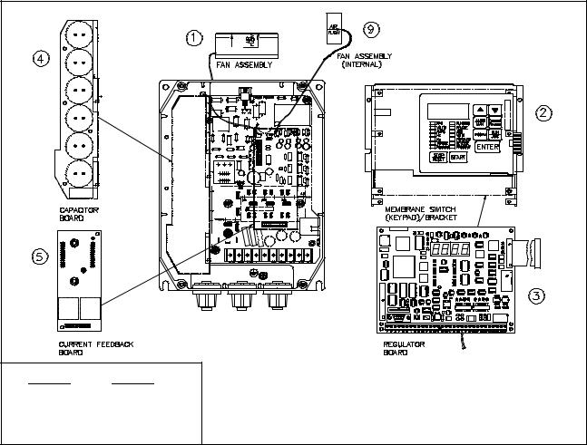
2.31 25 HP GV3000 Drive Components and Locations
The 1 25 HP GV3000 drives have the following main components. The identification numbers provided correspond to the numbers used in figures 2.2 to 2.4. Replacement parts are listed in chapter 9.
I1. Fan/Fan Assembly
I2. Membrane Switch (Keypad/Bracket)
I3. Regulator Printed Circuit Board (PCB)
I4. Capacitor PCB/Input Capacitors
I5. Current Feedback PCB
I6. Power PCB (15 25 HP drives only)
I7. Power Supply PCB (15 25 HP drives only)
I8. Gate Driver PCB (15 25 HP drives only)
I9. Internal Fan Assembly
10.IGBT Module
11.Diode Bridge
12.Fan Wire Harness
M/N |
M/N |
1V4150 |
3V4150 |
1V4450 |
3V4450 |
2V4150 |
5V4150 |
2V4450 |
5V4450 |
Figure 2.2 1 5 HP Drive Components and Locations
2 3
M/N |
7V4150 |
7V4250 |
10V4150 |
10V4250 |
Figure 2.3 7.5 10 HP Drive Components and Locations
2 4
M/N |
M/N |
15V4150 |
25G4150 |
15V4250 |
25G4250 |
20V4150 |
|
20V4250 |
|
Figure 2.4 15 25 HP Drive Components and Locations
2 5

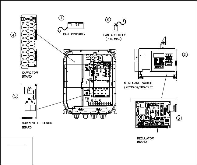
2.425 60 HP GV3000 Drive Components and Locations
The 25 60 HP drives have the following main components. The identification numbers provided correspond to the numbers used in figure 2.5. Replacement parts are listed in chapter 9.
1. Fan |
7. Power Supply Board |
|||
2. |
Membrane Switch (Keypad/Bracket) |
8. |
Gate Driver Board |
|
3. |
Regulator Board |
9. |
Internal Fan Assembly |
|
4. |
Bus Capacitors |
10. |
IGBT Module |
|
5. |
Not Used |
11. |
Diode Bridge |
|
6. |
Power Board |
12. |
Wire Harness |
|
M/N |
M/N |
M/N |
25V4150 |
40V4150 |
60G4150 |
25V4250 |
40V4250 |
60G4250 |
30V4150 |
50V4150 |
|
30V4250 |
50V4250 |
|
Figure 2.5 25 60 HP Drive Components and Locations
2 6
2.560 100 HP GV3000 Drive Components and Locations
The 60 100 HP drives have the following main components. The identification numbers provided correspond to the numbers used in figure 2.6. Replacement parts are listed in chapter 9.
1. |
Regulator Printed Circuit Board (PCB) |
9. Precharge Contactor |
|
2. |
Power Module Interface PCB |
10. |
Current Transformer |
3. |
Gate Driver PCB |
11. |
Ground Fault Transformer |
4. |
Bus Clamp PCB Right |
12. |
Output Reactor |
5. |
Bus Clamp PCB Left |
13. |
Precharge Resistor |
6. |
Intelligent Power Module PCB |
14. |
Bus Discharge Resistor |
7. Diode Bridge |
15. |
24 VDC Fan |
|
8. D C Bus Fuse |
16. |
Keypad |
|
|
14 |
14 |
|
7 |
|
12 |
|
16 |
|
10 |
10 |
6
1 |
|
|
5 |
4 |
|
|
||
3 |
|
|
2 |
|
|
11 |
10 |
|
9 |
||
|
||
|
8 |
13
15
M/N
50R4150
75R4150
Figure 2.6 60 100 HP Drive Components and Locations
2 7
2.6100 150 HP GV3000 Drive Components and Locations
The 100 150 HP drive has the following main components. The identification numbers provided correspond to the numbers used in figure 2.7. Replacement parts are listed in chapter 9.
1. |
Regulator Printed Circuit Board (PCB) |
10. |
Current Transformer |
|
2. |
Power Module Interface PCB |
11. |
Ground Fault Transformer |
|
3. |
Gate Driver PCB |
12. |
Output Reactor |
|
|
|
|||
4. Bus Clamp PCB Right |
13. |
Not Used |
||
5. Bus Clamp PCB Left |
||||
14. |
Bus Discharge Resistor |
|||
6. |
Intelligent Power Module PCB |
|||
|
|
|||
7. |
Thyristor Precharge Module |
15. |
24 VDC Fan |
|
|
|
|||
8. D C Bus Fuse |
16. |
Keypad |
||
9. |
Not Used |
17. |
Thyristor Firing Pulse PCB |
|
14
7
11
3
12
17
6
5
3
2 |
5 |
16
1
8
2
10
15
M/N
125R4150
Figure 2.7 100 150 HP Drive Components and Locations
2 8
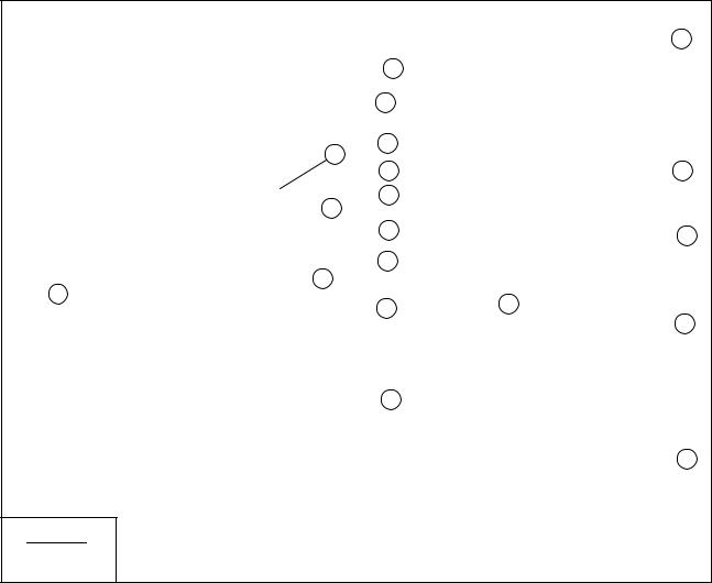
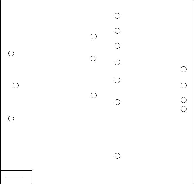
2.7Regulator Board Description
GV3000 drive regulation is performed by a microprocessor on the Regulator board. See figures 2.8 and 2.9. Drive operation is adjusted by the parameters entered through the keypad. The Regulator board accepts power circuit feedback signals, an external speed reference signal, and internal heat sensor feedback, as well as data from a pulse tachometer that is attached to the motor when set up for vector regulation. The Regulator board provides:
DPWM gating signals to the IGBT power devices
Based on the output of the control loop, the regulator sends PWM gating signals through the Current Feedback board to isolated drivers on the Gate Driver board. These drivers switch the Insulated Gate Bi polar Transistors (IGBTs), producing a Pulse Width Modulated (PWM) waveform that corresponds to the speed (vector regulation) or frequency (volts/hertz regulation) reference. The IGBTs can be switched at either a 2, 4 or 8 kHz carrier frequency.
DForm A and B contacts for drive status indicators
The Form A and B contacts are under control of the user via programmable parameters. A Form A or B transition can indicate drive status. The contacts are rated for 5 Amps resistive load at 250 VAC/ 30 VDC and are made available through the terminal strip.
DDisplay data for a four character display and fourteen indicator LEDs
The four character display is used to indicate drive parameters, parameter values, and fault codes. The fourteen single LEDs indicate drive status and mode, as well as identifying drive outputs whose values are displayed on the four character display.
DAn analog output
The analog output is a scaled voltage (0 10 VDC) or current (4 20 mA) signal proportional to either motor speed (RPM) or motor torque or current (%TORQUE). The current selection (via jumper J17) requires a power supply for operation. The power can be sourced from the pulse tachometer terminals (4 and 9) or from an external 15V power supply. See table 7.1, terminals 10 and 11, for more information. The analog output signal is available through the terminal strip.
DA snubber resistor braking signal
The 1 60 HP regulator provides a signal for use by an optional snubber resistor braking kit. The signal goes through an isolating driver, made available through the terminal strip.
Two Regulator boards are used on the GV3000 drives: 1 60 HP Regulator boards are used with
1 60 HP drives; 60 150 HP Regulator boards are used with 60 150 HP drives. As shown in figures 2.8 and 2.9, the Regulator boards are similar but have different Power Module interface connectors.
2 9
|
|
USER DISPLAY |
J5 |
|
|
|
|
|
|
|
Cable Ribbon Pin-26 |
J3 |
|
|
|
Cable |
|
|
|
Ribbon |
J7 |
|
J9 |
|
|
||
34-Pin |
|
|
|
J8 |
|
|
|
|
J17 |
J4 |
USER I/O TERMINAL STRIP |
J3 |
Option Board Connector |
J8 |
RS232C Port |
J4 |
Analog Input Jumper |
J9 |
Keypad/Display Connector |
J5 |
Power Module Feedback Cable |
J17 Analog Output Jumper |
|
J7 |
OIM (Optional) Connector |
|
|
Figure 2.8 1 60 HP Regulator Board Components and Locations
2 10
|
|
J16 |
60 Pin Ribbon Cable |
|
|
|
USER DISPLAY |
J3 |
|
|
|
Cable |
|
|
J9 |
Ribbon |
|
|
|
J7 |
|
|
|
Pin34 |
|
J17 |
J4 |
|
J8 |
|
|
|
|
|
USER I/O TERMINAL STRIP |
|
J3 |
Option Board Connector |
J9 Keypad/Display Connector |
|
J4 |
Analog Input Jumper |
J16 Power Module Feedback Cable |
|
J7 |
OIM (Optional) Connector |
J17 Analog Output Jumper |
|
J8 |
RS232C Port |
|
Figure 2.9 60 150 HP Regulator Board Components and Locations
2 11

2.7.1 Jumper Locations and Settings
Jumpers J4 and J17 on the Regulator board are factory set for voltage in and voltage out signals. Refer to figures 2.8 and 2.9 for their locations on the Regulator boards. If you need to change the jumpers' settings, use the following procedures.
CAUTION: Do not alter the setting of any jumper not described in this instruction manual. Failure to observe this precaution could result in damage to or destruction of the equipment.
2.7.1.1Analog Input Speed Reference Jumper
Jumper J4 is the analog speed/torque (U.000) reference jumper. This jumper selects either
+/- 10 VDC or 0 20 mA input. Parameters P.009, P.010, and P.011 are used in conjunction with the jumper. Note that if the position of jumper J4 is changed after the parameters are programmed, the software will not recognize that the input reference or polarity has been changed. Be sure to verify that parameters P.009, P.010, and P.011 are correct before starting the drive. Refer to instruction manual D2 3339 for more information.
Use the following procedure to set jumper J4:
DANGER
D C BUS CAPACITORS RETAIN HAZARDOUS VOLTAGES AFTER INPUT POWER HAS BEEN DISCONNECTED. AFTER DISCONNECTING INPUT POWER, WAIT FIVE (5) MINUTES FOR THE D C BUS CAPACITORS TO DISCHARGE AND THEN CHECK THE VOLTAGE WITH A VOLTMETER TO ENSURE THE D C BUS CAPACITORS ARE DISCHARGED BEFORE TOUCHING ANY INTERNAL COMPONENTS. FAILURE TO OBSERVE THIS PRECAUTION COULD RESULT IN SEVERE BODILY INJURY OR LOSS OF LIFE.
Step 1. Turn off input power to the drive and wait five minutes.
Step 2. Remove the cover from the drive by unscrewing the four attaching screws.
Step 3. Verify that the D C bus voltage is zero by following the procedure in section 9.3.
Step 4. Locate jumper J4 on the Regulator board. Refer to figures 2.8 and 2.9.
Step 5. Locate pin 1 on jumper J4. Move the jumper to the desired setting as shown in figure 2.10.
Step 6. Re attach the cover.
Step 7. Re apply input power.
Step 8. Verify that Terminal Strip Analog Input Offset (P.009), Terminal Strip Analog Input Gain (P.010), and Terminal Strip Analog Input Invert (P.011) are correctly set. Refer to instruction manual D2 3339 for more information.
Voltage Input Option |
Current Input Option |
||||
Pins 2 3 |
Pins 1 2 |
||||
+10 VDC |
0 20 mA |
||||
|
|
|
|
|
|
|
|
|
|
|
|
|
|
|
|
|
|
|
|
|
|
|
|
J4 |
J4 |
(default)
Figure 2.10 Jumper J4 Settings for Analog Input Speed Reference
2 12

2.7.1.2Analog Output Jumper
Jumper J17 is the analog output jumper. This jumper selects either a 0 10 VDC or 4 20 mA scaled signal output that is programmable for either speed or torque, parameter P.012. The jumper only selects a 0 10 VDC source voltage or 4 20 mA sink current to represent speed or torque. Note that the 4 20 mA current selection requires a power supply for operation as shown in table 7.1, terminals 10 and 11.
Use the following procedure to set jumper J17:
DANGER
D C BUS CAPACITORS RETAIN HAZARDOUS VOLTAGES AFTER INPUT POWER HAS BEEN DISCONNECTED. AFTER DISCONNECTING INPUT POWER, WAIT FIVE (5) MINUTES FOR THE D C BUS CAPACITORS TO DISCHARGE AND THEN CHECK THE VOLTAGE WITH A VOLTMETER TO ENSURE THE D C BUS CAPACITORS ARE DISCHARGED BEFORE TOUCHING ANY INTERNAL COMPONENTS. FAILURE TO OBSERVE THIS PRECAUTION COULD RESULT IN SEVERE BODILY INJURY OR LOSS OF LIFE.
Step 1. Turn off input power to the drive and wait five minutes.
Step 2. Remove the cover from the drive by unscrewing the four attaching screws.
Step 3. Verify that the D C bus voltage is zero by following the procedure in section 9.3.
Step 4. Locate jumper J17 on the Regulator board. Refer to figures 2.8 and 2.9.
Step 5. Locate pin 1 on jumper J17. Move the jumper to the desired setting as shown in figure 2.11.
Step 6. Re attach the cover.
Step 7. Re apply input power.
Step 8. Verify that parameter P.012 is set correctly for either speed or current.
Voltage Output Option |
Current Output Option |
||||
Pins 2 3 |
Pins 1 2 |
||||
+10 VDC |
0 20 mA |
||||
|
|
|
|
|
|
|
|
|
|
|
|
|
|
|
|
|
|
|
|
|
|
|
|
J17 |
J17 |
(default)
Figure 2.11 Jumper J17 Settings for Analog Outputs
2 13
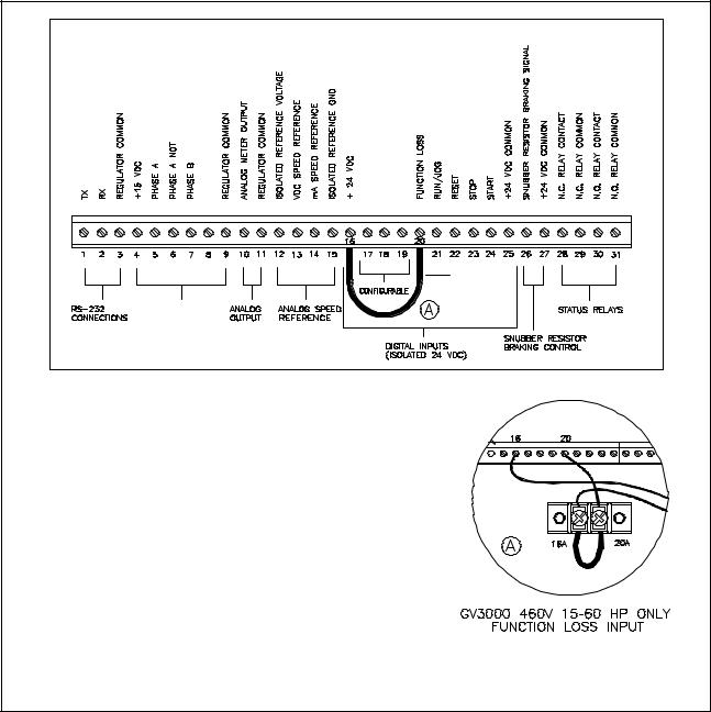
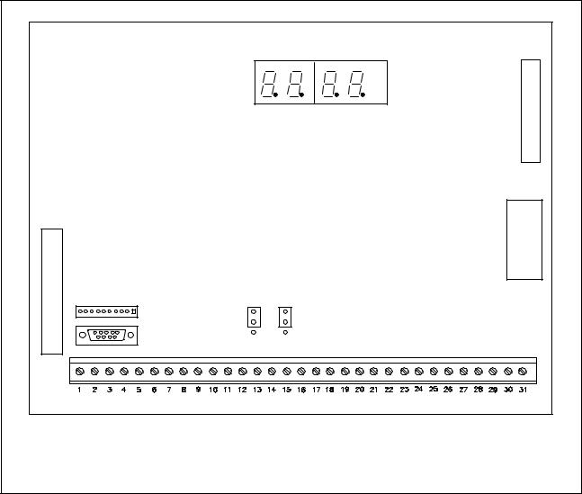
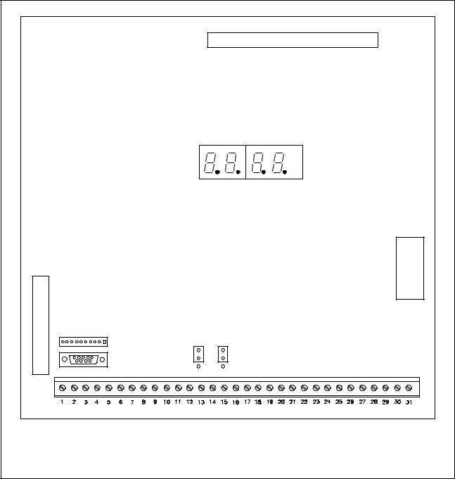
2.7.2 Wiring the Terminal Strip
The terminal strip on the Regulator board provides terminals for connecting customer I/O devices. See figures 2.8, 2.9, and 2.12. The following terminals are provided:
DTerminals 1 3: RS 232 connections
DTerminals 4 9: pulse tachometer connections
DTerminals 10 11: analog output connections
DTerminals 12 15: analog speed/torque reference connections
DTerminals 16 25: 24V D C digital input connections (1 60 HP Regulator boards only)
DTerminals 26 27: snubber resistor braking control connections (1 60 HP Regulator boards only)
DTerminals 28 31: status relay connections
PHASE B NOT |
DIGITAL INPUT 8 (REMOTE/LOCAL) |
DIGITAL INPUT 7 (RAMP1/RAMP2) |
DIGITAL INPUT 6 (FORWARD/REVERSE) |
|
|
|
FACTORY |
|
|
|
INSTALLED |
PULSE TACHOMETER |
|
|
|
CONNECTIONS |
|
|
|
|
|
|
WIRES BETWEEN TERMINALS 16+16A AND |
|
|
|
20 + 20A ARE NECESSARY FOR PROPER |
|
|
|
OPERATION OF THE FUNCTION LOSS |
|
|
|
INPUT. THEY SHOULD NOT BE REMOVED. |
Figure 2.12 Typical Terminal Strip Connections
2 14
 Loading...