


AADvance Controller

AADvance Controller
Demo Unit User Manual
ISSUE 1.2
DOCUMENT: 553850
SSB Technology

Demo Unit User Manual (AADvance Controller)
Notice
The content of this document is confidential to Rockwell Automation companies and
their partners. It may not be given away, lent, resold, hired out or made available to a
third party for any purpose without the written consent of Rockwell Automation.
This document contains proprietary information that is protected by copyright. All
rights are reserved.
The information contained in this document is subject to change without notice and
does not represent a commitment on the part of Rockwell Automation. The reader
should, in all cases, consult Rockwell Automation to determine whether any such
changes have been made. From time to time, amendments to this document will be
made as necessary and will be distributed by Rockwell Automation.
No part of this documentation may be reproduced or transmitted in any form or by
any means, electronic or mechanical, including photocopying and recording, for any
purpose, without the express written permission of Rockwell Automation.
All trademarks are acknowledged.
Disclaimer
It is not intended that the information in this publication covers every possible detail
about the construction, operation, or maintenance of a control system installation. You
should refer to your own (or supplied) system safety manual, installation instructions
and operator/maintenance manuals.
Revision and Updating Policy
This document is based on information available at the time of its publication; however,
the document contents are subject to change from time to time. You should contact
Rockwell Automation Technical Support by e-mail — support@icstriplex.com to
check if you have the latest version of this publication.
Your delivery document will state the software release level of your demo kit.
ii
Document: 553850 Issue 1.2: March 2011


Demo Unit User Manual (AADvance Controller)
Contents
Chapter 1 Introduction - Demo Unit....................................................................... 1-1
Demo Unit........................................................................................................................................................... 1-1
Dimensions and Weight................................................................................................................................... 1-2
Dimensions.................................................................................................................................................... 1-2
Weight............................................................................................................................................................ 1-3
Display Panel and Power Connectors .......................................................................................................... 1-3
Overview ............................................................................................................................................................. 1-4
Hardware Configuration ............................................................................................................................ 1-4
T9110 Processor Module........................................................................................................................... 1-5
Processor Module Specification ............................................................................................................... 1-6
T9100 Processor Base Unit....................................................................................................................... 1-7
T9300 I/O Base Unit (3 way) .................................................................................................................... 1-8
T9401/2 Digital Input Module, 24V dc, 8/16 channel........................................................................ 1-10
T9401/2 Digital Input Module Specification......................................................................................... 1-11
T9451 Digital Output Module, 24V dc, 8 channel .............................................................................1-12
T9451 Digital Output Module Specification ........................................................................................ 1-13
T9431/2 Analogue Input Module, 8/16 Channel................................................................................. 1-14
T9431/2 Analogue Input Module Specification ................................................................................... 1-15
Chapter 2 Setting Up the Demo Unit ..................................................................... 2-1
Create a New Project ...................................................................................................................................... 2-1
Changing the Properties of a Resource........................................................................................................ 2-2
Allocate IP Addresses for Network Communications ............................................................................. 2-3
Configure the IP Address of the Target Controller.................................................................................. 2-4
Downloading the Application to the Controller........................................................................................ 3-1
Setting Up the Controller for AADvance Workbench Communications ..................................... 3-1
Chapter 3 Configuring the Controller Processor Modules ................................... 4-1
About The Configuration Process................................................................................................................. 4-1
About the 9110 Module Editor ...................................................................................................................... 4-2
Configure the Top-level Process Safety Time (PST)................................................................................. 4-3
Configure the Processor Battery Alarm ...................................................................................................... 4-4
Configure the Serial Ports ............................................................................................................................... 4-4
Serial Port Protocols................................................................................................................................... 4-5
Serial Port Parameters................................................................................................................................ 4-5
Configure the Controller as an SNTP Client ............................................................................................. 4-6
Configure the Controller as an SNTP Server............................................................................................. 4-7
Using the Controller as a Modbus Slave...................................................................................................... 4-8
Support for Modbus Slave Exceptions.................................................................................................... 4-9
Configure the Controller Modbus Slaves ............................................................................................ 4-10
iv
Document: 553850 Issue 1.2: March 2011

v
Modbus Slave Communication Parameters ......................................................................................... 4-11
About T9110 Processor Variables...............................................................................................................4-12
Wire Processor Variables........................................................................................................................ 4-12
Unwire Processor Variables.................................................................................................................... 4-13
Status Integers ............................................................................................................................................ 4-13
Control Integers......................................................................................................................................... 4-15
Status Booleans .......................................................................................................................................... 4-15
Control Booleans....................................................................................................................................... 4-22
RTC Status Variables ................................................................................................................................ 4-23
RTC Program Variables............................................................................................................................4-25
RTC Control Variables.............................................................................................................................4-27
Chapter 4 Configuring the Controller I/O .............................................................. 5-1
About Configuring I/O Modules..................................................................................................................... 5-1
Defining the I/O Hardware Architecture............................................................................................... 5-2
Example Controller Configuration .......................................................................................................... 5-3
Assign I/O Modules to I/O Bus Slots ...................................................................................................... 5-4
Configure the I/O Module Process Safety Time................................................................................... 5-6
Wire Status Variables to I/O Modules.................................................................................................... 5-7
T9K_TA_GROUP_STATUS (I/O Module Status Information)........................................................ 5-8
About Configuring I/O Channels ................................................................................................................... 5-9
Wire Variables to Digital Input Channels ............................................................................................5-10
Wire Variables to Analogue Input Channels.......................................................................................5-11
Wire Variables to Digital Output Channels ........................................................................................5-12
Configuring Digital Inputs .............................................................................................................................. 5-12
TK9_DI_COMPACT and TK9_DI_FULL (Digital Inputs)............................................................... 5-13
Faulted State for Digital Inputs ...............................................................................................................5-14
About Threshold Values for Digital Inputs.......................................................................................... 5-14
Configuring Analogue Inputs......................................................................................................................... 5-18
TK9_AI_COMPACT and TK9_AI_FULL (Analogue Inputs).......................................................... 5-18
Faulted State for Analogue Inputs..........................................................................................................5-19
About HART............................................................................................................................................... 5-20
About Threshold Values for Analogue Inputs..................................................................................... 5-22
Configuring Digital Outputs ..........................................................................................................................5-26
TK9_DO_COMPACT and TK9_DO_FULL (Digital Outputs) ..................................................... 5-26
The State Variable for Digital Outputs................................................................................................. 5-27
Overcurrent Protection for Digital Outputs ......................................................................................5-28
Faulted State for Digital Outputs........................................................................................................... 5-29
Configure Advanced Channel Settings for Digital Outputs............................................................. 5-29
About Status Variables for Digital Output Modules................................................................................ 5-31
Wire Status Variables to a Digital Output Module............................................................................ 5-31
Unwire Status Variables from a Digital Output Module ..................................................................5-31
Status Booleans .......................................................................................................................................... 5-32
Field Power Status Integers..................................................................................................................... 5-33
Document: 553850 Issue 1.2: March 2011

Demo Unit User Manual (AADvance Controller)
This page intentionally left blank
vi
Document: 553850 Issue 1.2: March 2011
Introduction - Demo Unit
This chapter presents an overview of the demo unit.
In This Chapter
Demo Unit ........................................................................................................... 1-1
Dimensions and Weight.................................................................................... 1-2
Display Panel and Power Connectors ........................................................... 1-3
Overview ..............................................................................................................1-4
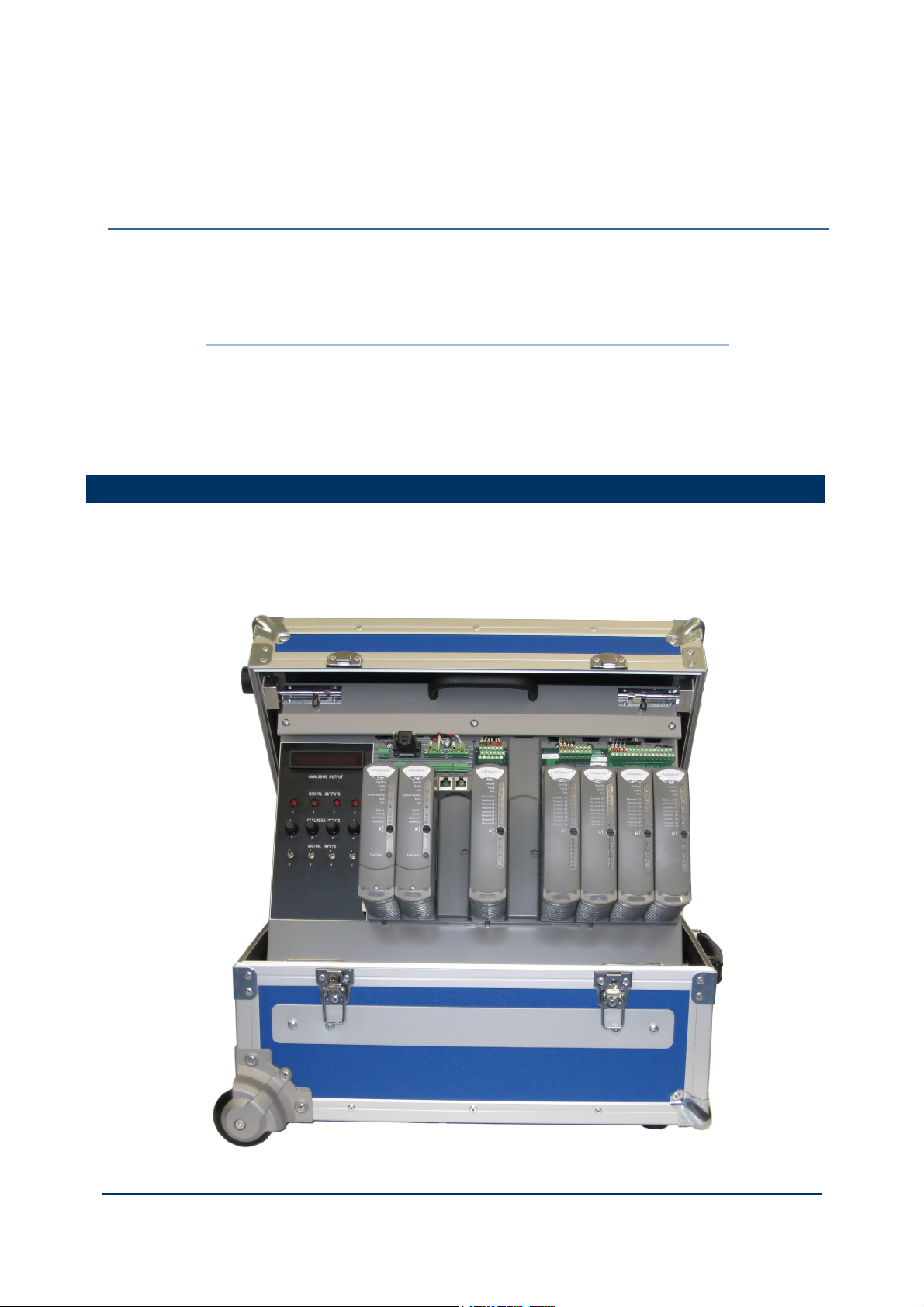
Demo Unit
The unit is mounted inside a secure protective box. The box is portable and when it is
placed on a flat surface the lid can be lifted and secured in the open position with two
bolts. It fully self contained and comes supplied with a set of modules and internal
wiring to a display and control panel.
Chapter 1
Document: 553850 Issue 1.2: March 2011
1-1
Demo Unit User Manual (AADvance Controller)
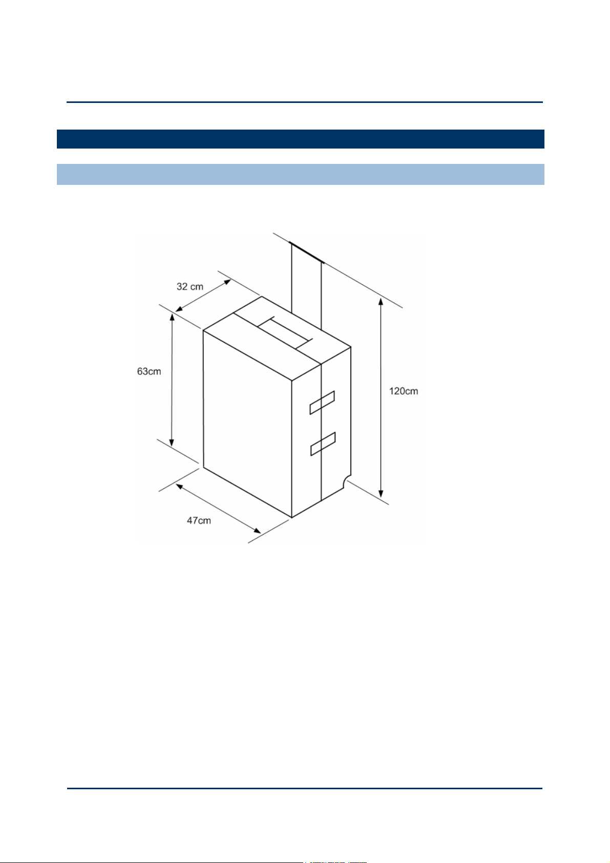
Dimensions and Weight
Dimensions
The portable unit has the following dimensions:
1-2
Document: 553850 Issue 1.2: March 2011
Weight
The unit weighs approximately 18 Kgms.
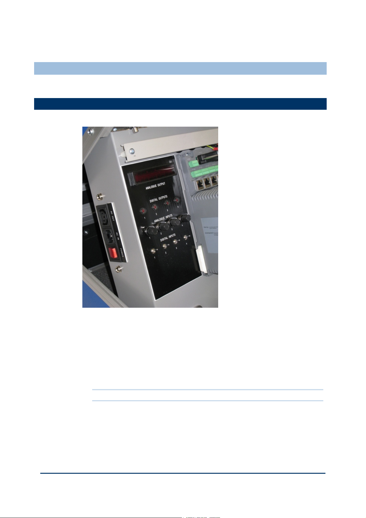
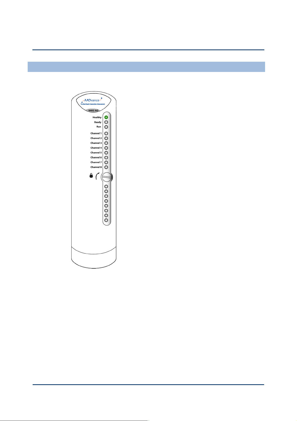
Display Panel and Power Connectors
The display panel provides a visual indication from the analogue and digital output
modules; it also has switches to drive digital inputs and potentiometers for analogue
inputs signals.The four switches are connected to channels 1 to 4 of the 9401 digital
input modul. The four analogue potentiometers are connected to channels 1 to 4 of
the dual 9431 analogue input modules. The LED indicators are connected to channels 1
to 4 of the dual digital output modules.
Two power sockets are located on the side of the display panel - one is for the input
mains power and the other output socket can provide power for external equipment.
The unit can be powered by 240V ac or 110V ac.
Note: The analogue out display is currently not used.
Document: 553850 Issue 1.2: March 2011
1-3
Demo Unit User Manual (AADvance Controller)
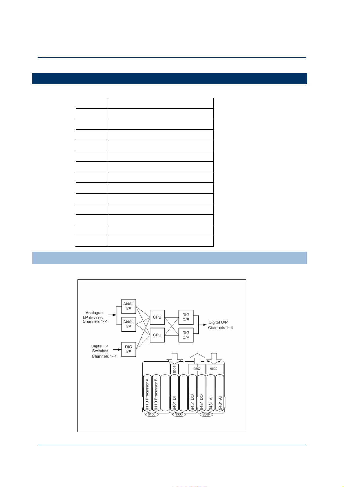
Overview
The Demo Unit is supplied with the following modules and termination assemblies:
Part No: Title
T9141 AADvance Demo Unit
T9110 Processor Module
T9110 Processor Module
T9000 Processor Base Unit
T9300 I/O Base unit (3-way)
T9401 Digital Input Module, 24V dc, 8 channel
T9801 Digital Input TA, 16 channel, simplex
T9451 Digital Output Module, 24V dc, 8 channel
T9451 Digital Output Module, 24V dc, 8 channel
T9852 Digital Output TA, 16 channel, Dual
T9431 Analogue Input Module, 8 channel
T9431 Analogue Input Module, 8 channel
T9832 Analogue Input TA, 16 channel, Dual
Hardware Configuration
The controller is configured as follows:
1-4
Document: 553850 Issue 1.2: March 2011
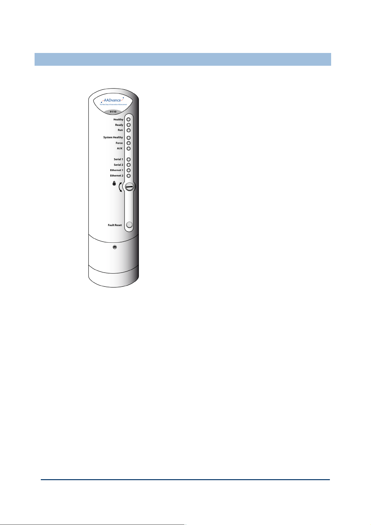
T9110 Processor Module
The T9110 processor module is the central processing unit of an
AADvance controller. The processor module carries out the
following critical process and safety controller tasks:
Execution of the AADvance Safety Kernel to solve
application logic
Interfacing with the controller I/O modules, reading and
processing input data and writing output data
Communication with other processor modules, both locally
and across the control network
Initiation of periodic diagnostics for the controller
Communication with other systems such as HMIs
Message encapsulation and verification for secure channel
communication to other nodes
The processor module is galvanically isolated from external
power supplies and data links so that any faults developed in the
field cannot cause the module to fail. The module will continue
to operate in the event of failure of one of its dual redundant
24V dc power supplies. The module incorporates under- and
over-voltage protection for its internal power supplies, which
provide a 'power valid' signal to the modules own diagnostics
microprocessor.
A processor module has two functionally independent,
electrically isolated Ethernet ports. Each port is separately
configurable for multiple protocols such as Modbus RTU, Open
Modbus/TCP and proprietary AADvance protocols, and its data
is available to every processor in the controller.
Two serial communications ports per processor are provided for Modbus RTU slave
communications. These ports are also functionally and electrically isolated from each
other. They support RS-485 (4– and 2–wire) communications and can be configured to
support asynchronous data rates from 1,200 to 115,200 baud.
The processor periodically initiates internal diagnostic tests which, together with a
watchdog circuit, monitor the processor internal performance. If the tests detect a
serious fault, the processor module will shut down. A controller can use one, two or
three processor modules. Using two or three processor modules provides a fault
tolerant processor architecture.
If a controller uses two or three processor modules, and one processor module
develops a fault, plant maintenance personnel can fit a new processor module while the
controller is on-line. The new processor module automatically carries out selfeducation and synchronizes with the other processors. Fault detection and fail-over in
redundant processor configurations is automatic and has no impact on controller
operation.
Document: 553850 Issue 1.2: March 2011
1-5

Demo Unit User Manual (AADvance Controller)
Processor Module Specification
Table 1: Processor Module Specification
Attribute Value
Functional Characteristics
Degradation 1oo1D, 1oo2D and 2oo3D
Processor clock 400MHz
Memory
Boot flash 512kB
SRAM 512kB
Bulk flash 64MB
SDRAM 32MB
Sequence of Events
Event Resolution Application Scan
Time-stamp Accuracy 5ms
Performance Characteristics
Safety Integrity Level (SIL) One module — non-safety applications, SIL1
and/or SIL2 safety applications
Two modules — SIL3 applications
Three modules — SIL3 fault tolerant and TMR
applications
Electrical Characteristics
Supply Voltage Redundant + 24V dc nominal; 18V dc to 32V
dc range
Power consumption (from 24V dc supply
6W
to controller)
Heat dissipation 6W
Maximum Surface Temperature of Module 43°C ± 2°C
Mechanical Specification
Dimensions (height × width × depth) 166mm × 42mm × 118mm
(6-½ in. × 1-5/8 in. × 4-5/8 in.)
Weight 430g (15 oz.)
Casing Plastic, non-flammable
1-6
Document: 553850 Issue 1.2: March 2011
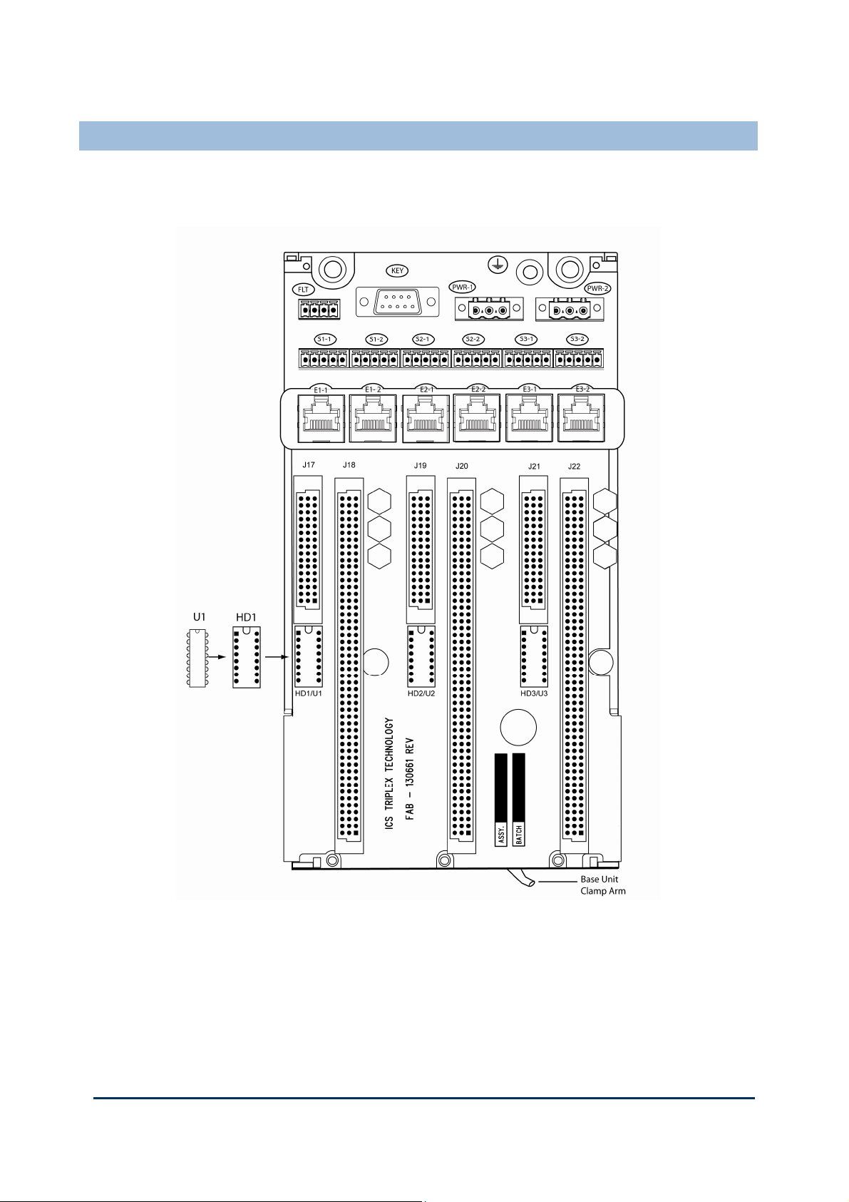
T9100 Processor Base Unit
Every AADvance controller has one T9100 processor base unit. A processor base unit
supports one, two or three modules depending on the architecture chosen for the
application.
Document: 553850 Issue 1.2: March 2011
1-7

Demo Unit User Manual (AADvance Controller)
The processor base unit provides the electrical connections between the T9110
processor modules, and the rest of the controller modules and has the following
connections:
Command and response bus connections for up to 48 I/O modules
Inter-processor links
Two Ethernet 100 BaseT connectors per processor
Two serial data connections per processor
Dual +24v System power
Ground stud
Program enable key
The processor base unit holds the IP address of each processor module separately in a
BUSP. This means that you can remove a defective processor module and install a new
one without needing to set up the IP address of the new module.
T9300 I/O Base Unit (3 way)
The AADvance controller has T9300 I/O base units for the I/O modules. An I/O base
unit supports up to three I/O modules (of any type), and their associated termination
assemblies.
It contains a passive backplane that provides the electrical connections between the
I/O modules and the T9100 processor base unit; i.e. the command and response buses
and the system power.
1-8
Document: 553850 Issue 1.2: March 2011
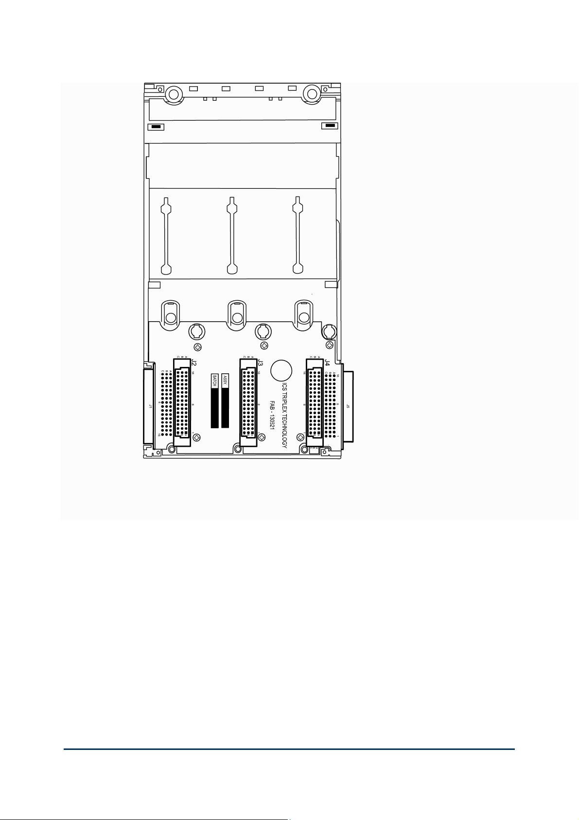
The bus and power connections from the processor base unit enter the backplane at
the left connector and are routed direct to the module connectors. The backplane
provides a connector at the right for the next I/O backplane. The connection to the
left of the backplane can connect to a processor base unit or another I/O base unit.
Adjacent base units clip together and are held in position by a plastic retaining clip.
Alternatively rows of I/O base units can be connected together using a T9310
expansion cable assembly.
Document: 553850 Issue 1.2: March 2011
1-9
Demo Unit User Manual (AADvance Controller)
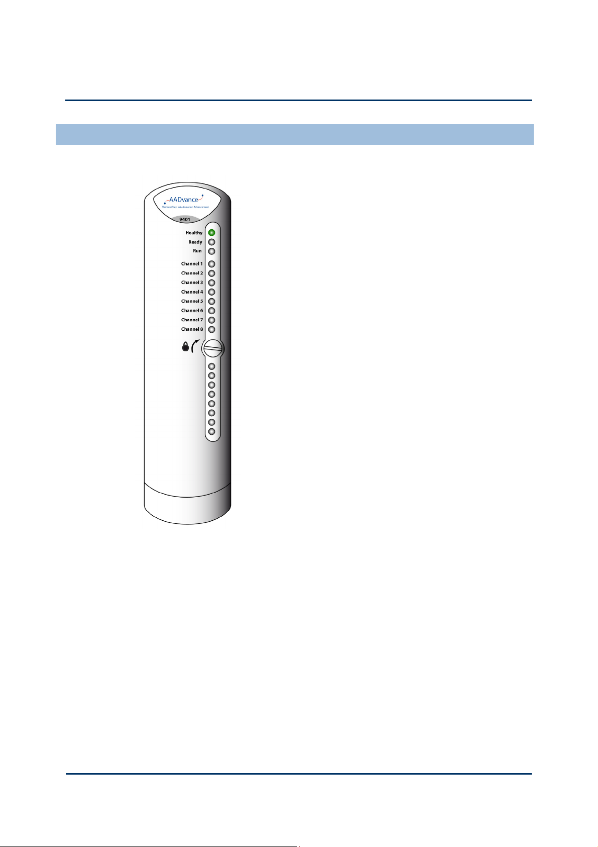
T9401/2 Digital Input Module, 24V dc, 8/16 channel
The T9401/2 digital input module monitors eight (T9401) or
sixteen (T9402) isolated digital input channels and notifies the
processor module of each field device state and channel
condition. Each channel provides both digital state and analogue
voltage data to the processor module for field device state, line
monitoring and field fault detection.
The input module provides local module and channel status
indications through its front panel LEDs, the same indications
can be connected to application variables and viewed at the
Workbench. Comprehensive diagnostics at both system and
module levels generate clear fault indications which help rapid
maintenance and repair.
The module incorporates signal and power isolation circuits,
which separate each input channel from the rest of the system,
protecting the controller from field faults. An independent
watchdog arrangement monitors the module operation and
provides additional fault containment by a shutdown mechanism
should a fault occur.
Digital Input Line Monitoring
Each digital input module parameters is set up through the AADvance Workbench
configuration tools. Switching levels for each digital input channel are configurable at
the module and the channel level. Each input has five configurable voltage bands (there
are eight distinct switching thresholds to allow hysteresis), each of which can be
adjusted through the AADvance Workbench to provide line monitoring, field loop
monitoring and additional field device diagnostics.
When a controller uses a digital input module in a dual or TMR
configuration, plant maintenance personnel can fit a new input
module without interrupting the input signals.
1-10
Document: 553850 Issue 1.2: March 2011

T9401/2 Digital Input Module Specification
Table 2: T9401/2 Digital Input Module Specification
Attribute Value
Functional Characteristics
Input Channels T9401: 8
Degradation 1oo1D, 1oo2D,2oo3D
Performance Characteristics
Safety Integrity Level IEC 61508 SIL3
Safety Accuracy Limit 1%
Sample Update interval (no filter) 5ms
Self Test Interval Not Applicable
Sequence of Events
Event Resolution
Time-stamp Accuracy
T9402: 16
1ms
5ms
Electrical Characteristics
Supply Voltage Redundant + 24Vdc nominal; 18V to
32V dc range
Data Input voltage +24V dc
Input Voltage Measurement Accuracy ± 0.5V
Module Power Consumption T9402: 1.5W
T9402: 2.2W
Module Heat Dissipation T9401: 1.5W
T9402: 2.2W
Channel Power connsumption 0.11W
Channel Isolation (channel to channel and channel
to chassis)
Maximum withstand
± 1.5KV dc
Mechanical Specification
Dimensions 166mm x 42mm x 118mm
(6½ in. × 1 21/32 in. × 4 21/32 in.)
Weight T9401: 280g (10 oz.)
T9402: 340g (12 oz.)
Casing Plastic, non-flammable
Document: 553850 Issue 1.2: March 2011
1-11

Demo Unit User Manual (AADvance Controller)
T9451 Digital Output Module, 24V dc, 8 channel
The T9451 digital output module interfaces up to eight final
elements and can switch 1A at 32V dc for each device. It
features voltage and load current monitoring on each channel,
reverse current protection and short and open circuit line
monitoring. It is designed to always be able to switch off an
output when demanded. No single failure within the module can
cause a stuck-on failure.The module supports dual redundant
power feeds for field devices without the need for external
diodes.
The output module isolates the processor module from the
output channel control and data management circuits, thus
protecting the processor module from potential faults in the
output control circuits and field connections.
The output channel protection activates when the channel load
exceeds a safe limit. The reverse voltage protection circuit in
each output channel ensures that externally applied voltages do
not generate current flow into the module outputs.
The module has self-checking functionality. Short circuit and
open circuit line monitoring is provided on all outputs. Internal
diagnostics carry out ongoing functionality checks ensuring that
the output channel command data is correctly transferred to the
output. In addition, the processor module initiates a test
sequence on each output channel, checking for 'stuck-on' and
'stuck-off' conditions on the output switch pairs.
Front panel LEDs provide module, channel
and field connection status indications.
These status indications can be connected
to application variables and viewed at the
AADvance.
When a controller uses a pair of digital output modules in a dual configuration, the two
fail-safe output switches on each channel are combined in a parallel arrangement so
that they automatically form a fault-tolerant output configuration.
1-12
Document: 553850 Issue 1.2: March 2011

T9451 Digital Output Module Specification
Table 3: T9451 Digital Output Module Specification
Attribute Value
Functional Characteristics
Number of output channels 8 per module
Degradation 1oo1D, 1oo2D
Performance Characteristics
Safety integrity level IEC 61508 SIL3
Self-test interval <30 mins (30s per module)
Electrical Characteristics
Supply Voltage Redundant +24V dc nominal;
Output characteristics:
Operating field supply voltage 0V to +50V dc
18V dc to 32V dc range
Maximum voltage without damage –1V to +60V dc
Nominal output voltage + 24V dc
Range + 18V to 32V dc
Output current 1A continuous per channel
Voltage Drop at Maximum Current < 1volt (approximately 0.9V)
Max output current before shutdown 6 A @ 60°C for all channels
Output overload protection
Surge 10A for up to 50ms
Continuous 1.5A
Power consumption
Module power (from controller 24V supply) 2W
Channel Field power (from source of field power) 24W (up to 192W per module)
Total maximum power consumption 198W (all 8 channels 'on' at maximum
current)
Heat dissipation 6W per module
Mechanical Specification
Dimensions (height × width × depth) 166mm × 42mm × 118mm
(6-½ in. × 1-21/32 in. × 4-21/32 in.)
Weight 340g (12 oz.)
Casing Plastic, non flammable
Document: 553850 Issue 1.2: March 2011
1-13
Demo Unit User Manual (AADvance Controller)
T9431/2 Analogue Input Module, 8/16 Channel
The T9431/2 analogue input module monitors eight (T9431) or
sixteen (T9432) isolated analogue input channels and notifies the
processor module of the field device value and channel
condition. Each channel provides digital state and analogue
process value data to the processor for process monitoring, line
monitoring and field fault detection.
The input module provides local module and channel status
indications through its front panel LEDs, the same indications
can be connected to application variables and viewed at the
Workbench. Comprehensive diagnostics at both system and
module levels provide clear indications which help rapid
maintenance and repair.
The module incorporates signal and power isolation circuits,
which separate each input channel from the rest of the system,
protecting the controller from field faults. An independent
watchdog arrangement monitors the module operation and
provides additional fault containment by a shutdown mechanism
should a fault occur.
Analogue Input Line Monitoring
Each analogue input module is set up through the AADvance Workbench. Monitoring
levels for each analogue input channel are configurable at the module and the channel
level. The default parameters are
Fault: 0 to 3.8mA
Normal: 3.8 to 22.0mA
Fault: > 22.0mA
Each input has five configurable voltage bands (there are eight distinct switching
thresholds to allow hysteresis), each of which can be adjusted to provide line
monitoring and field device diagnostics.
When a controller uses an analogue input module in a dual or
TMR configuration, plant operations personnel can fit a new
input module without interrupting the input signals.
1-14
Document: 553850 Issue 1.2: March 2011

T9431/2 Analogue Input Module Specification
Table 4: T9 Analogue Input Module Specification
Attribute Value
Functional Characteristics
Number of Field connections 16
Modules Supported: T9431: 8 channels
Degradation 1oo1D, 1oo2D and 2oo3D
Performance Characteristics
Safety integrity level IEC 61508 SIL3
Self test interval Not Applicable
Safety Accuracy 1%
Electrical Characteristics
Supply Voltage Redundant +24V dc nominal,
T9432: 16 channels
18V dc to 32V dc
Input Current
Nominal 4 to 20mA dc
Maximum range 0 to 24mA dc
Resolution 0.0039mA (12 bits over 4 to 20mA range)
Measurement accuracy at 25°C ± 0.05mA
Channel field power (from source of field
power)
75mW (based on a 25mA analogue loop
terminated by 120Ω)
Module power consumption T9431: 1.5W
T9432: 2.2W
Module Heat dissipation T9431: 1.5W
T9432: 2.2W
Channel Heat dissipation 0.06W
Channel Isolation (channel to channel and
channel to chassis)
Maximum withstanding ± 1.5kV dc
Mechanical Specification
Dimensions (height × width × depth) 166mm × 42mm × 118mm
(6-½ in. × 1-21/32 in. × 4-21/32 in.)
Weight T9431: 280g (10 oz.)
T9432: 340g (12 oz.)
Casing Plastic, non-flammable
Document: 553850 Issue 1.2: March 2011
1-15

Demo Unit User Manual (AADvance Controller)
This page intentionally left blank
1-16
Document: 553850 Issue 1.2: March 2011
Setting Up the Demo Unit
This chapter will describe the process to set up the Demo Unit ready for configuring
the processor and I/O modules.
In This Chapter
Create a New Project ....................................................................................... 2-1
Changing the Properties of a Resource ........................................................ 2-2
Allocate IP Addresses for Network Communications .............................. 2-3
Configure the IP Address of the Target Controller .................................. 2-4
Downloading the Application to the Controller......................................... 3-1
Create a New Project
The configuration process starts by creating a new AADvance project. To create a
new project do the following:
Chapter 2
1) Start the AADvance AADvance Workbench.
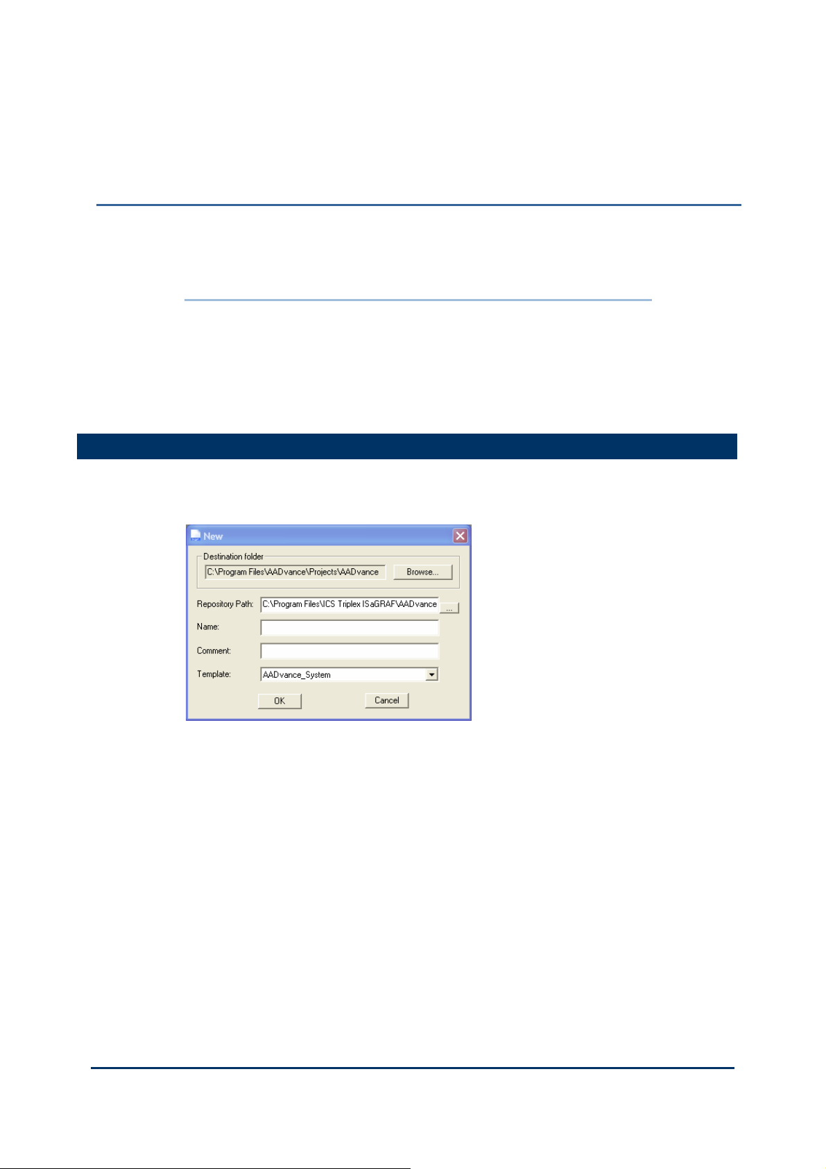
2) Select File then New Project/Library (<ctrl>+N).
The New dialog box opens.
3) Enter a project name (maximum of 128 characters) and add a comment line.
4) Choose the AADvance_System template from the drop down list, click OK.
The AADvance Workbench creates a project.
Document: 553850 Issue 1.2: March 2011
2-1

Demo Unit User Manual (AADvance Controller)
Changing the Properties of a Resource
Note: This procedure is only for Release 1.1 versions of the Controller.
If you change any properties of a Resource (see illustration), you have to clean the
project/library before you recompile the project. Do the following:
1) Select the Network tab on the Resources-dialog.
2) Click on each field in turn and delete the current value (using the delete or
backspace key).
3) Enter the following default values (or your own values).
Connect TimeOut = 10000
BindResp Timeout = 1000
MaxAge = 2500
BindingReq Timeout = 10000
Update Timeout = 60000
4) On the Resource - Properties dialog, click OK to save your changes.
5) On the main menu of the AADvance Workbench, select Project → Clean
Project/Library.
6) You can now choose to recompile your project.
2-2
Document: 553850 Issue 1.2: March 2011

Allocate IP Addresses for Network Communications
The AADvance system uses Internet Protocol (IP) for all communications between the
controller and the AADvance Workbench. This includes downloading the application
to the controller and real-time monitoring of the system in operation.
For many systems, the administrator of the local area network will allocate the address
for the controller. If this is not the case, choose an address from the ranges allocated
to private networks:
10.0.0.0 to 10.255.255.255 (10/8 prefix)
172.16.0.0 to 172.31.255.255 (172.16/12 prefix)
192.168.0.0 to 192.168.255.255 (192.168/16 prefix)
Each controller on a particular local area network must have a unique IP address.
Note: You must ensure that the two Ethernet ports on each T9110 processor
module are on different subnets.
Example
As an example you can use subnet masks to ensure that the two ports on a processor
module are on different subnets:
Ethernet port E1-1 Address: 10.10.1.1
Subnet Mask: 255.255.255.0
Ethernet port E1-2 Address: 10.10.2.1
Subnet Mask: 255.255.255.0
The subnet mask defines the first three digits of the IP address, in this case 10.10.1 and
10.10.2.
Document: 553850 Issue 1.2: March 2011
2-3
Demo Unit User Manual (AADvance Controller)
Configure the IP Address of the Target Controller
To connect the AADvance Workbench project to the target controller you have to
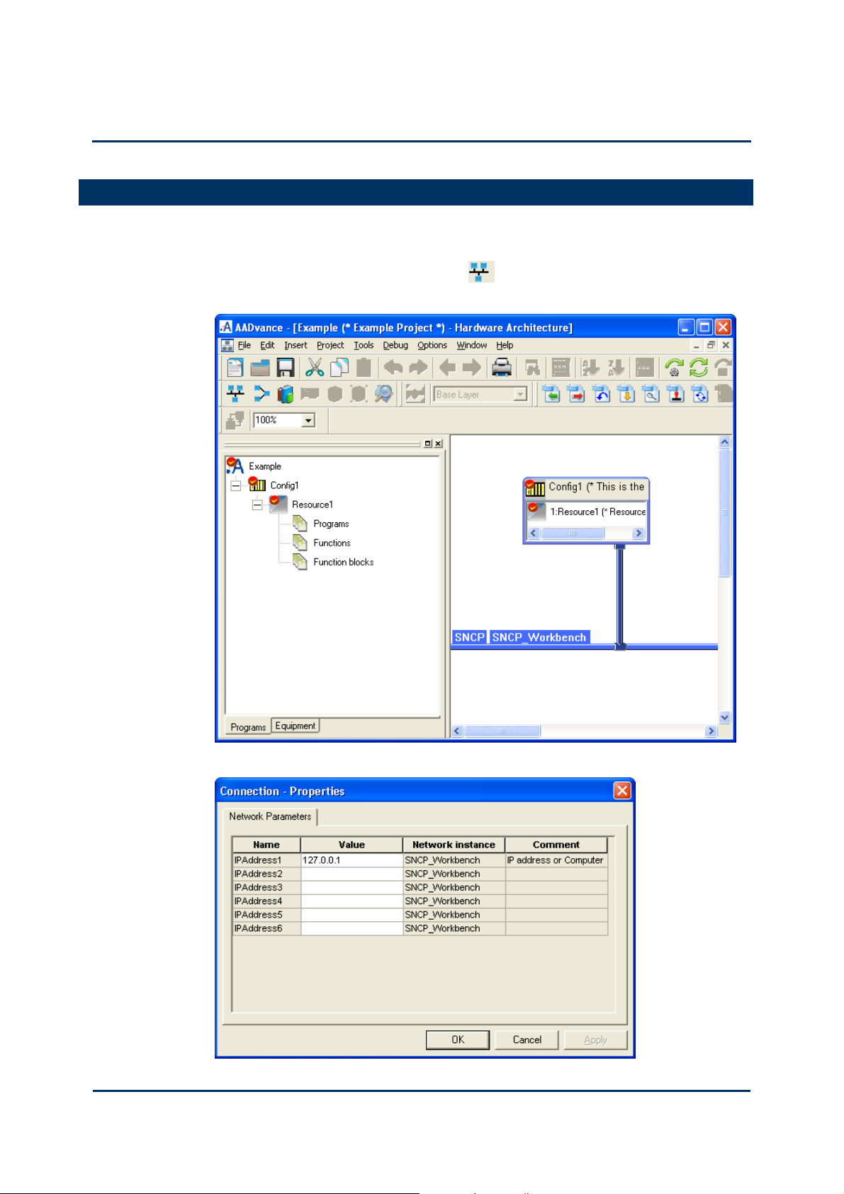
tell the project the IP addresses allocated to the controller. Do the following:
1) Select the Hardware Architecture view
connection between the SNCP network line and the configuration.
then double-click on the vertical
2) The Connection - Properties dialog box opens.
2-4
Document: 553850 Issue 1.2: March 2011

3) Enter the IP Addresses in the Value field for each of the required Ethernet
network. Press Enter after typing each IP address.
Note: The value shown above is a default value. Enter a value that you require.
4) Click OK.
You have now configured the IP addresses of the configuration to match the
controller.
Document: 553850 Issue 1.2: March 2011
2-5

Chapter 3
Downloading the Application to the Controller
This chapter describes the procedures for connecting the AADvance Workbench to
the controller so that the application can be downloaded.
In This Chapter
Setting Up the Controller for AADvance Workbench Communications3-1
Setting Up the Controller for AADvance Workbench Communications
The AADvance controller stores a resource number and IP address information.
These details have to match those defined in the AADvance Workbench for the
application. After you have configured these details the AADvance Workbench can
communicate with the controller. You use the AADvDiscover utility to set up the
controller for AADvance Workbench communications.
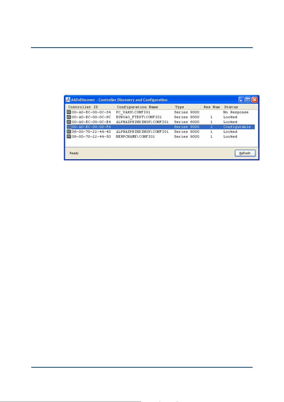
Controller Discovery and Configuration
The AADvDiscover Utilility uses a discovery and configuration protocol (proprietary
to Rockwell Automation) to set the controller IP address within the AADvance
Workbench and to scan the broadcast domain for other AADvance controllers. The
utility locates each controller by its unique MAC Address. Having located a particular
controller to be configured, the utility lets you configure the resource number and IP
Address to be stored in the controller; after you have done this, the AADvance
About the AADvDiscover Utility
Workbench can communicate with the other controller.
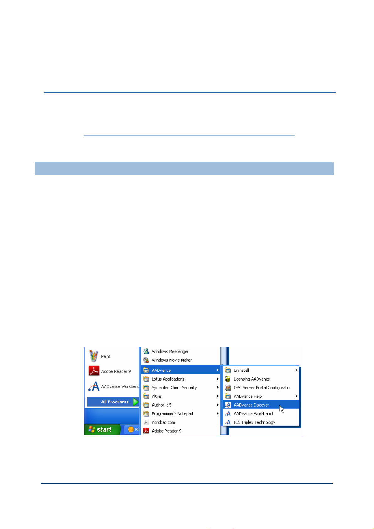
The AADvDiscover utility is installed when you install the AADvance Workbench, and
appears on the Start menu of the computer. Click on AADvance Discover to start
the AADvDiscover utility.
Document: 553850 Issue 1.2: March 2011
3-1
Demo Unit User Manual (AADvance Controller)
The AADvDiscover utility displays a list of the AADvance controllers on the
broadcast network, and reports a status for each one:
Configurable
Locked
No response
Double-clicking on an entry in the list lets you inspect the resource and IP address
settings for a controller. There is also a Refresh button, which makes a scan of the
network and creates a new list.
A controller is configurable when the program enable key is present (this plugs into
the KEY connector on the processor base unit) and either no application is loaded or
an application is loaded but not running. The status will be locked if the controller
reports that one or more of these criteria has not been met.
If the AADvDiscover utility reports a status of 'no response' for a controller, either
the controller has been turned off or the communications between the computer
running the utility and the controller have failed. Check the power to the controller
and check the connection, and click the Refresh button.
The AADvDiscover utilty also reports a status of 'in progress' and 'Pending
restart'. 'In progress' appears while the controller accepts new settings. 'Pending
restart' means the controller is waiting for manual intervention from you; cycle the
power to the controller.
Configure the Controller Resource Number
When you build a new AADvance controller, or install a new 9100 processor base
unit, you have to configure the resource number stored in the controller. This is a kind
of device address, and it must also be configured in the application.
The procedure to configure the resource number uses the AADvDiscover utility. To
set the resource number do the following:
1) Make a note of the controller's MAC address (Controller ID); this is shown on
a label on the processor base unit. Install at least one 9110 processor module into
the processor base unit.
2) Make sure the program enable key is inserted in the KEY connector on the
processor base unit.
3) Start the AADvDiscover tool from the Start menu:
3-2
Document: 553850 Issue 1.2: March 2011
 Loading...