


AADvance Controller

AADvance
The Next Step in Automation
AADvance Controller
Configuration Guide
Issue: 07
DOCUMENT: 553633
ICSTT-RM405F-EN-P

ii
Document: 553633
ICSTT-RM405f-EN-P
Issue: 07
Configuration Guide (AADvance Controller)
This page intentionally left blank

Document: 553633
ICSTT-RM405f-EN-P
Issue :07
iii
Notice
In no event will Rockwell Automation be responsible or liable for indirect or
consequential damages resulting from the use or application of this equipment. The
examples given in this manual are included solely for illustrative purposes. Because of
the many variables and requirements associated with any particular installation,
Rockwell Automation does not assume responsibility or reliability for actual use based
on the examples and diagrams.
No patent liability is assumed by Rockwell Automation, with respect to use of
information, circuits, equipment, or software described in this manual.
Reproduction of this manual in whole or in part, without written permission of
Rockwell Automation is prohibited.
All trademarks are acknowledged.
Disclaimer
It is not intended that the information in this publication covers every possible detail
about the construction, operation, or maintenance of a control system installation. You
should refer to your own (or supplied) system safety manual, installation instructions
and operator/maintenance manuals.
Revision and Updating Policy
This document is based on information available at the time of its publication; however,
the document contents are subject to change from time to time. You should contact
Rockwell Automation Technical Support by e-mail — icstsupport@ra.rockwell.com to
check if you have the latest version of this publication.
© Copyright Notice, Rockwell Automation 2012
This document contains proprietary information that is protected by copyright. All
rights are reserved.
Documentation Feedback
Your comments will help us to serve your documentation needs better. If you
discover any errors or have any suggestions on how to improve this publication send
your comments to our product support group: icstsupport@ra.rockwell.com
This Configuration Guide applies to Release 1.3.

iv
Document: 553633
ICSTT-RM405f-EN-P
Issue: 07
Configuration Guide (AADvance Controller)
Issue Record
Issue
Date
Comments
01
Jan 2009
First Issue
01A
Aug 2009
Release 1.1 Issue
01B
Aug 2009
Updated issue for per review comments
02
Nov 2009
Release 1.1.1
03
July 2010
Update for CRs
04*
Oct 2011
Release 1.2
05
Apr 2012
Updated Release 1.2 version with Analogue Output Module
information added.
06
June 2012
Release 1.3 & 1.3.1
07
June 2013
Update to Add information to on-line update topics
was originally designated Issue: Release 1.2
Document: 553633
ICSTT-RM405f-EN-P
Issue :07
v
Notes and Symbols used in this manual
This symbol calls attention to items which "must" be considered and implemented
when designing and building an AADvance controller for use in a Safety
Instrumented Function (SIF). It appears extensively in the AADvance Safety Manual.
Note: Notes are used extensively to provide important information about the
product.
Standard Warnings and Cautions
WARNING
ELECTRICAL ARCS AND EXPLOSION RISK IN HAZARDOUS
AREAS
If you connect or disconnect wiring, modules or communications cabling while
power is applied, an electrical arc can occur. This could cause an explosion in
hazardous location installations. Do not remove wiring, fuses, modules or
communications cabling while circuit is energized unless area is known to be
non hazardous.
Failure to follow these instructions may result in personal injury.
WARNING
MAINTENANCE
Maintenance must be carried out by people who are experienced in working on
electronic equipment and in particular safety related systems.They should have
knowledge and experience of local operating and safety standards. Failure to
follow these recommendations may result in situations that can lead system
damage and even personal injury.
CAUTION
RADIO FREQUENCY INTERFERENCE
Most electronic equipment is influenced by Radio Frequency Interference.
Caution should be exercised with regard to the use of portable communications
equipment around such equipment. Signs should be posted in the vicinity of the
equipment cautioning against the use of portable communications equipment.
CAUTION
HEAT DISSIPATION AND ENCLOSURE POSITION
System and field power consumption by modules and termination assemblies is
dissipated as heat. You should consider this heat dissipation on the design and
positioning of your enclosure; e.g. enclosures exposed to continuous sunlight
will have a higher internal temperature that could affect the operating
temperature of the modules. Modules operating at the extremes of the
temperature band for a continuous period can have a reduced reliability.

vi
Document: 553633
ICSTT-RM405f-EN-P
Issue: 07
Configuration Guide (AADvance Controller)
Forward
This manual defines how to configure an AADvance controller using the AADvance
Workbench to meet your SIF application requirements.
Who Should Use This Manual
This manual is intended primarily for System Integrators. The information contained in
this manual is aimed at engineers experienced in building and setting up safety-related
systems. It is expected that the users have been trained and have a thorough
understanding of the intended application.
Note: System Integrators are responsible for compliance to local, national and
international standards that apply for the application that AADvance is being used for.
System Integrators are responsible for resolving any conflicts between this document
and the applicable project codes and standards.
If AADvance is being used for any Safety Functions the System Integrators are
responsible for applying the requirements defined in the AADvance Safety Manual.


viii
Document: 553633
ICSTT-RM405f-EN-P
Issue 07:
Configuration Guide (AADvance Controller)
Contents
Chapter 1 Introduction ............................................................................................. 1-1
Purpose and Scope ............................................................................................................................................ 1-1
AADvance Workbench and Software Development Environment ....................................................... 1-1
About The Configuration Process ................................................................................................................. 1-3
Integrating the AADvance Controller with Other Systems .................................................................... 1-4
Application Scan Model .................................................................................................................................... 1-5
Scan Times ..................................................................................................................................................... 1-6
Chapter 2 Software Installation ............................................................................... 2-1
AADvance WorkbenchLicensing Options ................................................................................................... 2-1
Install the AADvance Workbench and Utilities ......................................................................................... 2-1
Add and Activate a New AADvance Workbench License ...................................................................... 2-5
Updating or Upgrading an Existing License ................................................................................................. 2-7
Update or Upgrade a Hardware/Software License Key ..................................................................... 2-7
Using a Floating License Server ................................................................................................................ 2-8
Set Up a Server for Hardware Floating Licenses ................................................................................. 2-9
Set Access to Floating Licenses .............................................................................................................. 2-10
Chapter 3 Connecting the Workbench to the Controller .................................... 3-1
Setting Up the Controller IP Address for AADvance Workbench Communications ...................... 3-1
Controller IP Address Setting ................................................................................................................... 3-1
AADvanceDiscover Utility ........................................................................................................................ 3-1
About Discover Communications ................................................................................................................. 3-2
Discover Communications Fault-Finding ..................................................................................................... 3-3
Configure the Controller Resource Number ............................................................................................. 3-3
Configure the IP Address in the Controller ............................................................................................... 3-5
Save and Load a Configuration ................................................................................................................. 3-7
Chapter 4 Configuring the Processor Modules ....................................................... 4-1
View Module Firmware Versions ................................................................................................................... 4-1
ControlFLASH Firmware Upgrades .............................................................................................................. 4-5
Stage 1: Installing the ControlFLASH Firmware ................................................................................... 4-6
Upgrade the Processor Module Recovery Mode Firmware .............................................................. 4-9
Stage 2: Installing the ControlFLASH Firmware Kit for OS, FPGA, LSP and BUSP .................. 4-14
Upgrade Processor OS, FPGAFPGA, LSP and BUSP Firmware ..................................................... 4-15
Configure Controller Type (Standard or Eurocard) ............................................................................... 4-19
Configure the Top-level Process Safety Time (PST) ............................................................................... 4-20
Configure the Processor Battery Alarm .................................................................................................... 4-21
Configure the Serial Ports ............................................................................................................................. 4-22
Serial Port Protocols ................................................................................................................................. 4-23

Document: 553633
ICSTT-RM405f-EN-P
Issue 07:
ix
Serial Port Parameters .............................................................................................................................. 4-23
Time Synchronization (SNTP) ...................................................................................................................... 4-24
Configure the Controller as an SNTP Client ...................................................................................... 4-24
Configure the Controller as an SNTP Server ..................................................................................... 4-25
Using the Controller as a Modbus Slave .................................................................................................... 4-27
Support for Modbus Slave Exceptions .................................................................................................. 4-27
Configure the Controller Modbus Slaves ............................................................................................ 4-28
Modbus Slave Communication Parameters ......................................................................................... 4-29
Transparent Communication Interface (TCI) ........................................................................................... 4-30
TCI Configuration ...................................................................................................................................... 4-30
DiffServ Configuration .................................................................................................................................... 4-32
Configure DiffServ ..................................................................................................................................... 4-32
Ethernet Forwarding ....................................................................................................................................... 4-34
Configure Ethernet Forwarding ............................................................................................................. 4-34
About T9110 Processor Variables ............................................................................................................... 4-36
Wire Processor Variables ........................................................................................................................ 4-36
Unwire Processor Variables .................................................................................................................... 4-37
Status Integers ............................................................................................................................................ 4-38
Control Integers ......................................................................................................................................... 4-40
Status Booleans .......................................................................................................................................... 4-40
Control Booleans ....................................................................................................................................... 4-47
RTC Status Variables ................................................................................................................................ 4-48
RTC Program Variables ............................................................................................................................ 4-50
RTC Control Variables ............................................................................................................................. 4-53
Set the Processor Clock ................................................................................................................................ 4-57
Chapter 5 Configuring the Controller I/O .............................................................. 5-1
About Configuring I/O Modules ..................................................................................................................... 5-1
Defining the I/O Hardware Architecture ............................................................................................... 5-2
Example Controller Configuration .......................................................................................................... 5-3
Assign I/O Modules to I/O Bus Slots....................................................................................................... 5-4
Enable or Disable the On-line Update Feature .................................................................................... 5-8
Perform an On-line Update ....................................................................................................................... 5-9
Configure the I/O Module Process Safety Time ................................................................................. 5-12
Wire Status Variables to I/O Modules .................................................................................................. 5-12
T9K_TA_GROUP_STATUS (I/O Module Status Information) ...................................................... 5-14
About Configuring I/O Channels ................................................................................................................. 5-16
Wire Variables to Digital Input Channels ............................................................................................ 5-16
Wire Variables to Analogue Input Channels ....................................................................................... 5-17
Wire Variables to Digital Output Channels ........................................................................................ 5-18
Wire Variables to Analogue Output Channels ................................................................................... 5-19
Configuring Digital Inputs .............................................................................................................................. 5-19
T9K_DI_COMPACT and T9K_DI_FULL (Digital Inputs) ............................................................... 5-20
Faulted State for Digital Inputs ............................................................................................................... 5-21
Threshold Values for Digital Inputs ....................................................................................................... 5-22

x
Document: 553633
ICSTT-RM405f-EN-P
Issue 07:
Configuration Guide (AADvance Controller)
Configuring Analogue Inputs ......................................................................................................................... 5-26
T9K_AI_COMPACT and T9K_AI_FULL (Analogue Inputs) .......................................................... 5-26
Faulted State for Analogue Inputs .......................................................................................................... 5-27
HART ............................................................................................................................................................ 5-28
About Threshold Values for Analogue Inputs ..................................................................................... 5-38
Configuring Digital Outputs .......................................................................................................................... 5-41
T9K_DO_COMPACT and T9K_DO_FULL (Digital Outputs) ..................................................... 5-41
The State Variable for Digital Outputs ................................................................................................. 5-43
Overcurrent Protection for Digital Outputs ...................................................................................... 5-44
Faulted State for Digital Outputs ........................................................................................................... 5-45
Configure Advanced Channel Settings for Digital Outputs ............................................................. 5-45
Status Variables for Digital Output Modules............................................................................................. 5-47
Wire Status Variables to a Digital Output Module............................................................................ 5-47
Unwire Status Variables from a Digital Output Module................................................................... 5-48
Status Booleans .......................................................................................................................................... 5-48
Field Power Status Integers ..................................................................................................................... 5-49
Configuring Analogue Outputs ..................................................................................................................... 5-51
The State Variable for Analogue Outputs ............................................................................................ 5-51
T9K_AO_COMPACT and T9K_AO_FULL (Analogue Outputs)................................................. 5-52
Faulted State for Analogue Outputs ...................................................................................................... 5-53
Configure Advanced Channel Settings for Analogue Output Channels ....................................... 5-53
Chapter 6 Setting Up ................................................................................................ 6-1
Create a New Project ...................................................................................................................................... 6-1
Compiler Verification Tool ............................................................................................................................. 6-2
Enable the Compiler Verification Tool (CVT) ...................................................................................... 6-2
Allocate IP Addresses for Network Communications ............................................................................. 6-4
Configure the IP Address of the Target Controller .................................................................................. 6-5
Chapter 7 Using the Dictionary ............................................................................... 7-1
About the Dictionary ........................................................................................................................................ 7-1
Properties for AADvance Variables .............................................................................................................. 7-1
Create or Modify Variables in the Dictionary ............................................................................................ 7-4
Edit the Contents of a Cell in the Dictionary ....................................................................................... 7-4
Edit the Contents of a Row in the Dictionary ...................................................................................... 7-6
SOE Service Parameters ............................................................................................................................. 7-7
Chapter 8 Using CIP over EtherNet/IP ................................................................... 8-1
CIP over EtherNet/IP ........................................................................................................................................ 8-1
Define a CIP Network ...................................................................................................................................... 8-2
Data Types for CIP over Ethernet/IP ............................................................................................................ 8-4
Using the Dictionary with CIP ........................................................................................................................ 8-4
CIP in the Dictionary View ........................................................................................................................ 8-4
Parameters for CIP Producer and Consumer Varaibles .................................................................... 8-5
Configure an AADvance Variable as a Producer ....................................................................................... 8-6

Document: 553633
ICSTT-RM405f-EN-P
Issue 07:
xi
Defining The AADvance Controller as a CIP Producer .......................................................................... 8-6
Configure an AADvance Variable as a Consumer ..................................................................................... 8-8
Obtaining the Connection Status for a Consumed Variable ................................................................. 8-10
CIP within the Application Scan Cycle ....................................................................................................... 8-11
About the RSLogix 5000 Configuration ..................................................................................................... 8-11
Rules for Counting Connections ................................................................................................................. 8-11
Set the RSLogix UNICAST Configuration ................................................................................................. 8-14
Further Information on CIP over Ethernet/IP .......................................................................................... 8-15
Chapter 9 Configuring Modbus Master ................................................................... 9-1
Modbus Master ................................................................................................................................................... 9-2
Modbus Standards ............................................................................................................................................. 9-2
Modbus Master Hardware and Physical Connections .............................................................................. 9-2
Modbus Master Command Set ....................................................................................................................... 9-4
Modbus Data Types and Addressing ............................................................................................................. 9-4
Modbus Message Scheduling ........................................................................................................................... 9-5
Handling Modbus Communication Errors ............................................................................................. 9-7
Modbus Statistics ............................................................................................................................................... 9-7
Modbus Service Parameters ............................................................................................................................ 9-8
Diagnosing Modbus Communications and Slave Devices ........................................................................ 9-8
Modbus Exception Responses ........................................................................................................................ 9-9
AADvance Objects for Modbus Master ....................................................................................................... 9-9
Modbus Master Capacities .............................................................................................................................. 9-9
Planning for Modbus Master .......................................................................................................................... 9-10
Physical Connections for Modbus RTU ..................................................................................................... 9-10
Connect a Slave Device, Full Duplex .................................................................................................... 9-11
Connect Multiple Slave Devices, Full Duplex...................................................................................... 9-12
Connect a Slave Device, Half Duplex ................................................................................................... 9-13
Connect Multiple Slave Devices, Half Duplex..................................................................................... 9-14
Configure the Serial Ports for Modbus Master ........................................................................................ 9-15
Serial Port Parameters .............................................................................................................................. 9-16
Physical Connections for Modbus TCP ...................................................................................................... 9-16
Setting up the Project for Modbus Master Operation ............................................................................ 9-16
About the Modbus Master Bus ............................................................................................................... 9-17
Insert the Modbus Master Bus ................................................................................................................ 9-17
Create a Modbus Master Object ................................................................................................................. 9-18
Modbus Master Communication and Control Settings .................................................................... 9-19
Configure a Modbus Master Object for Modbus RTU ..................................................................... 9-21
Configure a Modbus Master Object for Modbus TCP ..................................................................... 9-22
Controlling a Modbus Master Object ......................................................................................................... 9-25
Modbus Ping Mode, Interval and Address............................................................................................ 9-26
Configure Statistics for a Modbus Master Object ................................................................................... 9-32
Modbus Statistics Parameters ................................................................................................................. 9-32

xii
Document: 553633
ICSTT-RM405f-EN-P
Issue 07:
Configuration Guide (AADvance Controller)
Create Links to Modbus Slaves .................................................................................................................... 9-33
Modbus Slave Link Identification and Control Settings .................................................................... 9-34
Configure a Modbus Slave Link for Modbus RTU.............................................................................. 9-36
Configure a Modbus Slave Link for Modbus TCP .............................................................................. 9-37
Choosing Names for Modbus Objects ................................................................................................. 9-38
Modbus Slave ID......................................................................................................................................... 9-38
Modbus Slave Wait Interval ..................................................................................................................... 9-38
Modbus Ping Mode, Interval and Address............................................................................................ 9-38
Modbus Slave Commands .............................................................................................................................. 9-39
Serial Port .................................................................................................................................................... 9-39
Ethernet and Serial Port ........................................................................................................................... 9-39
Modbus Slave Link Control and Status Registers..................................................................................... 9-41
Modbus Slave Link Control Register ..................................................................................................... 9-41
Modbus Slave Link Status Register ........................................................................................................ 9-42
Add Messages for a Modbus Slave ............................................................................................................... 9-43
Modbus Slave Link Message Parameters .............................................................................................. 9-45
Controlling a Modbus Message ............................................................................................................... 9-46
Configure Statistics for a Modbus Slave Link ............................................................................................ 9-46
Modbus Statistics Parameters ................................................................................................................. 9-47
Remove a Slave Link ........................................................................................................................................ 9-47
Remove all Slave Links .................................................................................................................................... 9-48
Remove a Modbus Master Object ............................................................................................................... 9-48
Chapter 10 SNCP and Variable Bindings ................................................................ 10-1
SNCP Safety Networks .................................................................................................................................. 10-1
SNCP Networks ........................................................................................................................................ 10-2
Set Up Multiple SNCP Networks .......................................................................................................... 10-5
SNCP KVB Driver Timeout Values ....................................................................................................... 10-7
Configure Bindings ................................................................................................................................... 10-10
SNCP Binding Error Variables .............................................................................................................. 10-13
Chapter 11 Peer-to-Peer Network .......................................................................... 11-1
Peer to Peer Features ..................................................................................................................................... 11-1
Peer to Peer Configuration Process ........................................................................................................... 11-2
Create a Peer to Peer Network .................................................................................................................. 11-2
Peer-to-Peer Subnet Controller Configuration ....................................................................................... 11-3
Set up the Peer IP Addresses and Status Variable ............................................................................. 11-6
Peer to Peer Data Boards.............................................................................................................................. 11-6
Configure Input Boards .................................................................................................................................. 11-7
Configure Analogue Input Boards ............................................................................................................... 11-7
Configure Digital Input Boards ................................................................................................................... 11-10
Wire Digital Input Board Status Variables ......................................................................................... 11-11
Wire Digital Input Channel Data Variables ....................................................................................... 11-12
Configure Output Boards ............................................................................................................................ 11-13

Document: 553633
ICSTT-RM405f-EN-P
Issue 07:
xiii
Configure Analogue Output Boards ......................................................................................................... 11-14
Configure Digital Output Board................................................................................................................. 11-16
Peer to Peer Configuration Example 1 ..................................................................................................... 11-18
Peer-to-Peer Controller Setting Summary ........................................................................................ 11-19
Peer to Peer Data Summary ................................................................................................................. 11-24
Chapter 12 Glossary of Terms ................................................................................. 12-1
Chapter 13 Additional Resources ............................................................................ 13-1
Regional Offices ................................................................................................................................................ 13-2


Document: 553633
ICSTT-RM405f-EN-P
Issue 07
1-1
This chapter provides a brief overview of the AADvance Workbench and this manual.
In This Chapter
Purpose and Scope ............................................................................................. 1-1
AADvance Workbench and Software Development Environment ........ 1-1
About The Configuration Process .................................................................. 1-3
Integrating the AADvance Controller with Other Systems ..................... 1-4
Application Scan Model ..................................................................................... 1-5
Purpose and Scope
This technical manual defines the process you should follow to configure a new system
or re-configure an existing system. It includes background information and detailed
procedures for the following:
Setting the controller IP Address
Defining the processor configuration
Defining the variables in the Dictionary
Configuring the I/O modules and channels
setting up Modbus and CIP
The step-by-step instructions are based on using the AADvance Workbench
configuration tools.
Also included is reference information about module status parameters and I/O
variables to help you decide which variable types to use, and included is a brief
description of the data values provided by the I/O modules.
The instructions for installing the Workbench, choosing a licensing option and
connecting the application to the controller are also covered by this manual.
AADvance Workbench and Software Development Environment
The 9110 Processor Module runs the Workbench, it must have the following
specification:
Operating Systems:
Windows XP with Service Pack 3
Windows Vista, Windows 7 & Server 2003 in both 32-bit and 64-bit versions
Note: Network Licensing - Windows 64-bit version will only work with the USB
licsensing method.
Chapter 1
Introduction

1-2
Document: 553633
ICSTT-RM405f-EN-P
Issue 07
Configuration Guide (AADvance Controller)
CAUTION: Do not use XP Professional x64 edition
Network port (10/100 Base T Ethernet)
Access to a CD-ROM drive, for software installation
If the application adopts the dongle licensing option for the software, the processor
module will also require one free USB port.
The AADvance workstation uses software that enables you to design the complete
control strategy as one, then to target parts of the strategy at each controller.
Interaction between the resources is automatic, significantly reducing the complexity of
configuration in a multi-resource solution.
The workstation software, known as the Workbench is compliant with IEC61131
industrial standard and has the following powerful features:
the regulation of the flow of control decisions for an interacting distributed control
system
providing for the consistency of data
providing a means for synchronous operation between devices
eliminating the need to have separate synchronous schemes
easing the development and maintenance of robust systems
The Workbench is a complete software development environment for a controller.
It lets you create local and distributed control applications using the five languages of
IEC 61131-3. Engineers can choose one language or a combination of languages that
best suits their knowledge and programming style and the nature of the application.
It is a secure development environment that requires a hardware or software license
to run on a PC. There is also a Program Enable key (not applicable to a Euro
Controller) that must be plugged into the processor base unit to allow the user to
modify and download the application resource or access the AADvance Discovery tool
to set or change the controller IP address. The Program Enable key when it is
removed protects the application from unauthorized access.
The development environment includes:
tools for program development
program documentation
function block library management
application archiving
database configuration
import/export utilities
on-line monitoring
off-line simulation and controlled on-line changes.

Document: 553633
ICSTT-RM405f-EN-P
Issue 07
1-3
Programs can be simulated and tested and tested on the computer before downloading
to the controller hardware. Also provided is a set of configuration tools that enables
you to define the hardware architecture in the software; set up the processor
functionality; and connect application variables to the Workbench application
resource program that will monitor processor and I/O module status information and
report I/O channel data values to the Workbench. Resource Control applications can
be distributed across several hardware platforms, communicating with each other
through secure networks.
CAUTION
WORKBENCH FOR USE IN SAFETY APPLICATIONS
If the Workbench is used for safety related applications then you must follow
the safety application guidelines contained in the AADvance Safety Manual (Doc
No: 553630).
About The Configuration Process
The process begins by creating a project and allocating the IP addresses for its
communications to the AADvance controllers. You can then configure the network
communications parameters for the project.
You then define the hardware architecture. This assigns the I/O modules to empty slot
numbers on the processor buses. There are two IO Busses each can be assigned up to
24 I/O modules.
Note: If you change the physical arrangement of the hardware after you have
configured a controller using the AADvance Workbench, you must change the
AADvance Workbench configuration to match the changed hardware arrangement.
Important Note: For Release 1.3 you can change the I/O module configuration with
an on-line update without having to stop the running application. However, if you are
still using an earlier product release the I/O module configuration cannot be changed
with an on-line update.
You should now define your module status and the I/O channel variables and their
properties inthe Dictionary. The AADvance Workbench provides you with a wide
range of variables types to choose from including a set of structured variables. Set up
enough variables to cover all the I/O points and module status variables for your
controller architecture. If necessary, you can add new variables at any time during
configuration of a system and the AADvance Workbench or after reconfiguration.
You should now allocate tag names to the variables you want to use. If you chose
structured variables for I/O channels, the AADvance Workbench automatically
generates a set of additional variable elements with the same tag name for each
element type.
In the next stage of the process you define the T9110 processor module functionality
and set up connections to a group of processor module status parameters. Here you
will enter values for functions such as the serial port settings, process safety time, and
SNTP and Modbus services.

1-4
Document: 553633
ICSTT-RM405f-EN-P
Issue 07
Configuration Guide (AADvance Controller)
The AADvance Workbench provides pre-defined I/O module status parameters for
each module to which you assign application variables.
Finally you connect (wire) each I/O channel to structured variables. These structured
variables report input the channel status and define output data values.
You define hardware redundancy in the AADvance Workbench when you define the
hardware configuration. During the allocation of I/O modules to empty slots, you are
presented with the option to add two or three modules. When you choose the two or
three option the AADvance Workbench automatically allocates the modules to a
group of adjacent slots. The AADvance Workbench then only allows you to configure
one set of I/O channels to the group.
Note: You do not need to define redundancy for the processors. The AADvance
Workbench automatically connects to all three processors after their IP addresses
have been set up in the AADvance Workbench.
Integrating the AADvance Controller with Other Systems
The AADvance controller interfaces to existing control systems and plant monitoring
equipment. This enables, for example, a control system to read the state of sensors
connected to the controller.
The interfaces are through the controller network (Ethernet) ports and serial ports,
and support the following protocols:
CIP over Ethernet/IP
Modbus RTU
Open Modbus/TCP
OPC
Document: 553633
ICSTT-RM405f-EN-P
Issue 07
1-5
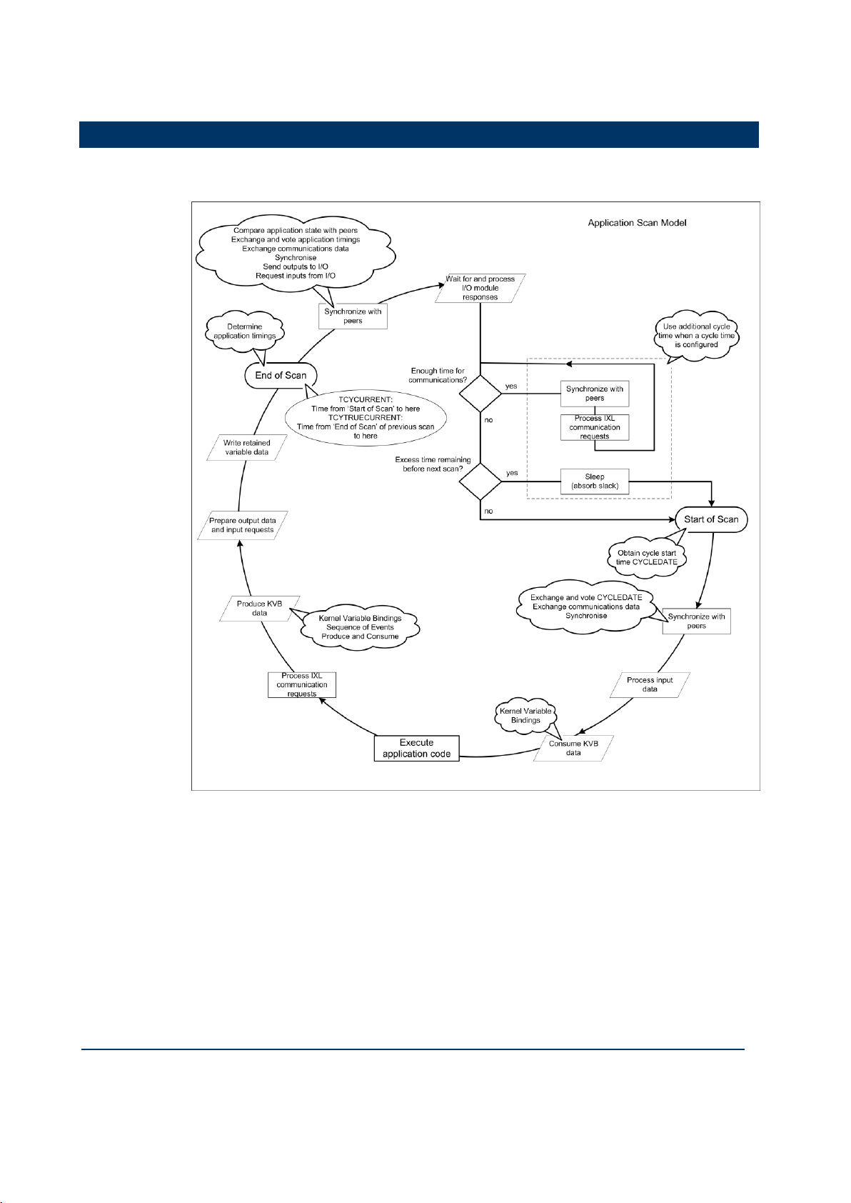
Application Scan Model
The application scan model for the AADvance controller is shown in the following
illustration:

1-6
Document: 553633
ICSTT-RM405f-EN-P
Issue 07
Configuration Guide (AADvance Controller)
Scan Times
The following scan times were taken from a test system consisting of production
modules.
Module
Scan Time
T9401 Digital input module, 24V dc, 8 channel
Single
Dual
Triple
1.23ms
1.73ms
2.08ms
T9431 Analogue input module 24V dc, 8 channel
Single
Dual
Triple
1.26ms
1.91ms
2.33ms
T9451 Digital output module, 24V dc, 8 channel
Single
Dual
1.43ms
2.44ms
AADvance Workbench Sleep Period
57.2ms
Scan overhead per module
0.09ms
The tests did not measure the effect of logic complexity and communications loading.
The scan time is:
(Number of module groups x scan time shown above) + Sleep Period + (Total
modules x scan overhead)
The scan time will vary by up to +/- 5ms (not including the effect of logic and
communications).
Throughput time is the time from input change to output action. Due to the discrete
nature of the scan, the throughput time will vary between one and two scans.
Note: The AADvance application scan time is limited to a minimum of 64ms to allow
all processes to run. Small applications will report a scan time of approximately 57 -
61ms. Large applications may have longer scan times but each scan time will be
consistent to within approximately 5ms.
An example configuration scan time:
T9431 Analogue input simplex modules x 30
T9451 Digital output simplex modules x 18
Total I/O modules = 48
Estimated scan time = (30 x 1.23ms) + (18 x 1.43ms) + 57.2ms + (48 x 0.09ms)
= 125.1ms

Document: 553633
ICSTT-RM405f-EN-P
Issue 07
1-7
Throughput time:
min = 125.1ms
Avg = 187.6ms
Max = 250.1ms


Document: 553633
ICSTT-RM405f-EN-P
Issue 07
2-1
This chapter provides the instructions to install and license the AADvance
Workbench.
In This Chapter
AADvance WorkbenchLicensing Options .................................................... 2-1
Install the AADvance Workbench and Utilities .......................................... 2-1
Add and Activate a New AADvance Workbench License ....................... 2-5
Updating or Upgrading an Existing License .................................................. 2-7
AADvance WorkbenchLicensing Options
You can use the AADvance Workbench for a trial period of 30 days with a
promotional license. To use a fully operational version you must purchase a license key
from Rockwell Automation. License keys come in two forms:
T9082/3U Single User Hardware License: a hardware license key is a dongle
that is delivered with the software. To activate the license you insert the dongle
into the USB port of your computer. This type of license allows the license to be
moved to other PC's, but only the PC with the USB Dongle installed will allow the
Workbench to be started.
T9082/3D Single User Software License: a software license key (hard disk
key) is obtained and activated through the AADvance License Manager. This
type of license establishes the license on a specific PC or another PC, but only the
PC with the software key activated will allow the Workbench to be started.
When you purchase a single user license you can choose from the following feature
sets:
T9082 Multiscan (PRS): Single user, single controller license.
T9083 Distributed (PRD): Single user, multiple controllers license.
Network licenses are also available:
T9084U Network User License: A network license (USB dongle) allows the
users to license copies of the AADvance Workbench on PC's so long as they have
a continuous network connection to a central license server.
Install the AADvance Workbench and Utilities
When Installing a single user license you do not need to install the License Manager
separately unless you are running a network installation; You just need to run the
License Manager to activate or enable a license.
Chapter 2
Software Installation
2-2
Document: 553633
ICSTT-RM405f-EN-P
Issue 07
Configuration Guide (AADvance Controller)
Installing Workbench Part Numbers: T9082U. T9082D, T9083U & T9083D
Notes:
You require "Admin" rights on the PC the Workbench is to be installed on.
The Install CD has an Autorun, so simply inserting the CD will launch the
AADvance Products Installer.
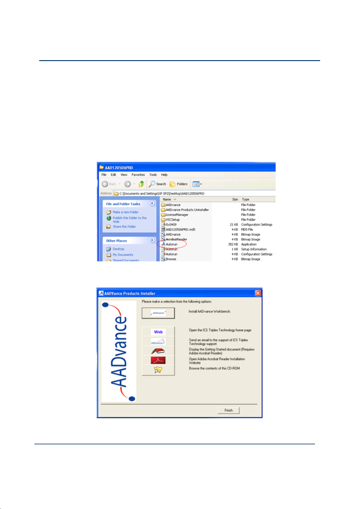
If however the Workbench is being installed using a downloaded CD image, to
launch the AADvance Products Installer you must run the Autorun
application from the following folder:
To install the Workbench and its Utilities do the following:
1) Click on the Install AADvance Workbench button.
Document: 553633
ICSTT-RM405f-EN-P
Issue 07
2-3
Accept the License Agreement and the installation will commence.
The default is to install both the Workbench and the License Manager
components; we recommend proceeding with the defaults.
When the install commences you will be given the option of changing the
location for the install, we recommend you accept the default settings.
During the install you will be asked if you want shortcuts placed on your
desktop, simply answer yes or no depending on your preference.
When the installation is complete you will be prompted to restart the
computer, this must be done prior to using the Workbench.
Install Part Number T9084U Network License
Notes:
You require "Admin" rights on the PC the Workbench is to be installed on.
The Install CD has an Autorun, so simply inserting the CD will launch the
AADvance Products Installer.
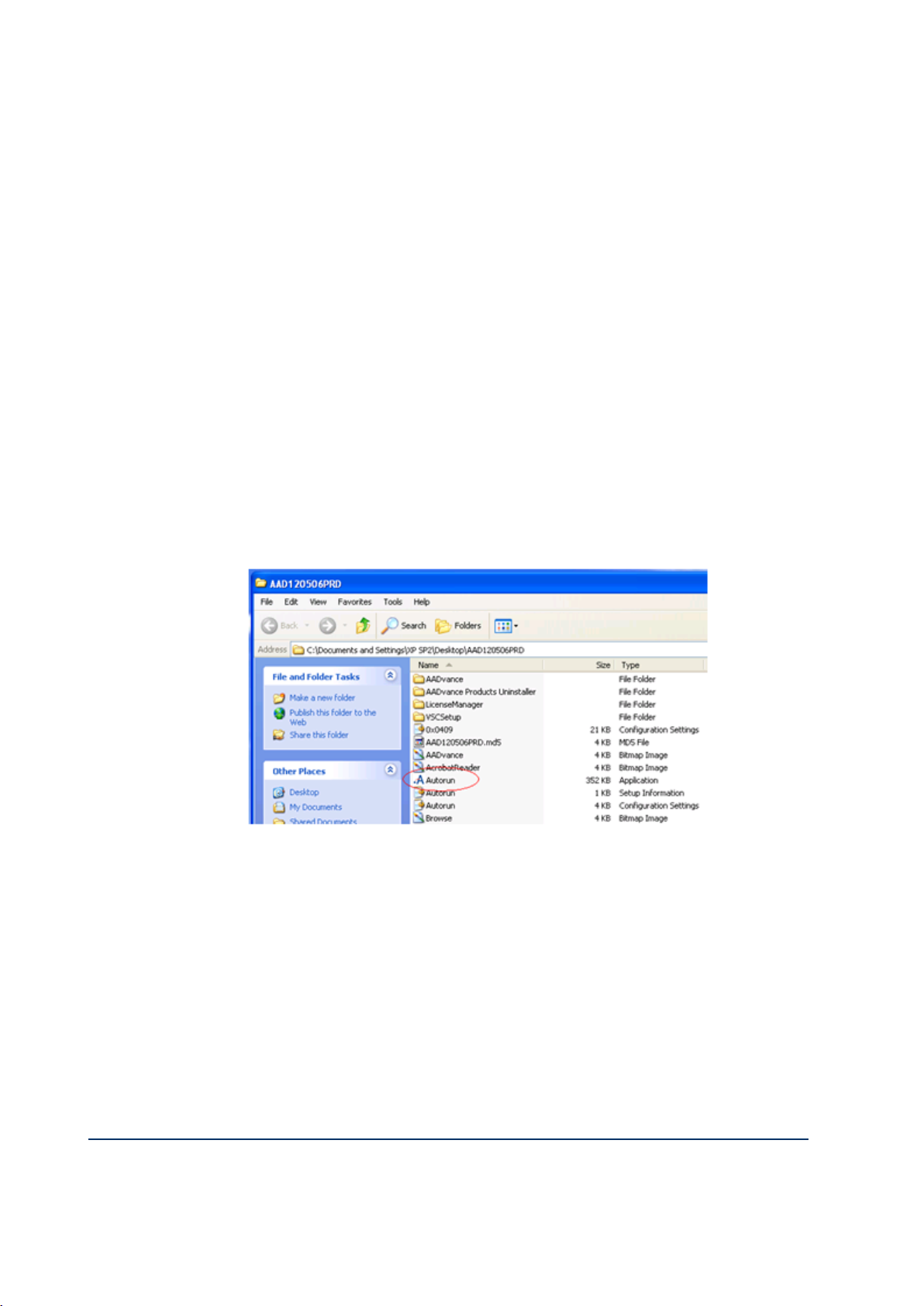
If however the Workbench is being installed using a downloaded CD image, to
launch the AADvance Products Installer you must run the Autorun
application from the following folder:
To use Network based licensing, you have to install the Workbench and the
License Manager on any PC’s you wish to run the Workbench on and you have to
install the License Manager on the PC or Server that will act as the network
License Server.
1) Click on the Install AADvance Workbench button.
You must accept the License Agreement before the installation will commence.
The default is to install both the Workbench and the License Manager
components; we recommend proceeding with the defaults.
When the install commences you will be given the option of changing the
location for the install, we recommend you accept the default settings.
During the install you will be asked if you want shortcuts placed on your
desktop, simply answer yes or no depending on your preference.

2-4
Document: 553633
ICSTT-RM405f-EN-P
Issue 07
Configuration Guide (AADvance Controller)
When the installation is complete you will be prompted to restart the
computer, this must be done prior to using the Workbench.
Install the License Manager on the Network License Server
1) Click on the Install AADvance Workbench button at the top of the list of the
AADvance Products Installer.
You must accept the License Agreement before the installation will commence.
2) Select the License Manager Only.
Note: The License Server can also function as a Workbench, if this is the intended
method of operation proceed with the defaults.
When the install commences you will be given the option of changing the
location for the install, we recommend you accept the default settings.
During the install you will be asked if you want shortcuts placed on your
desktop, simply answer yes or no depending on your preference.
When the installation is complete you will be prompted to restart the
computer, this must be done prior to using the Workbench.
Document: 553633
ICSTT-RM405f-EN-P
Issue 07
2-5
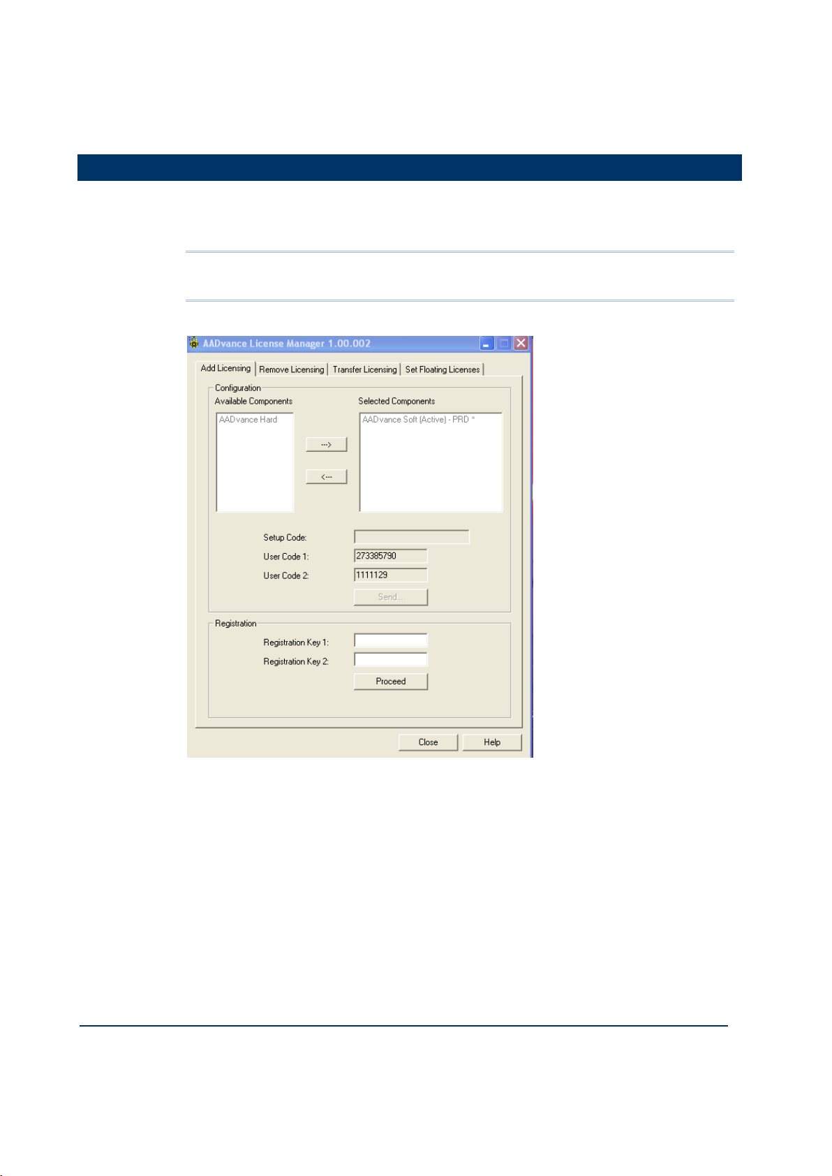
Add and Activate a New AADvance Workbench License
You use the following AADvance License Manager window to add and activate a new
Software (Disk Based) AADvance Workbench licenses. USB licenses are detected
automatically.
Note: You need only one set of user codes and registration keys to activate the
license key, irrespective of the feature set or number of licenses ordered.
To add a new license do the following:
1) From the Start menu select AADvance Licensing AADvance.
The AADvance License Manager dialog box opens.
2) Select the Add Licensing tab.
3) Select an AADvance Soft component from the Available Components, then
click the button to move the selection to the Selected Components
window.
2-6
Document: 553633
ICSTT-RM405f-EN-P
Issue 07
Configuration Guide (AADvance Controller)
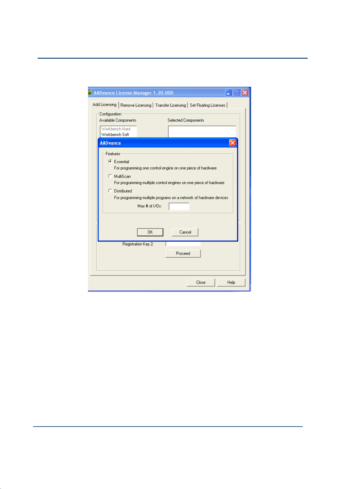
4) The AADvance license Features options appears.
5) Select the license feature and leave the Max#of I/Os blank. When you purchase a
single user license you can choose from the following feature sets:
T9082 Multiscan (PRS): Single user, single controller license.
T9083 Distributed (PRD): Single user, multiple controllers license.
6) A Setup Code and two User Codes appear in their respective fields.
7) Click Send.
A License Manager window opens telling you to register by email, click Yes.
8) At this point your email client may ask your permission to access an external email
address, click the Yes button
A pre-addressed email form opens containing the following:
- the selected components details
- setup code and both user codes
9) Enter the contact information and the purchase order number into the email form.
Document: 553633
ICSTT-RM405f-EN-P
Issue 07
2-7
10) Send the email.
Note: If the computer does not have an email client configured, copy the text and send
from another computer.
The original Setup Codes and User Codes together with the new
Registration Keys are returned to you in an email.
1) Check that the Setup Code and User Codes are the same as the original ones.
2) Enter the Registration Keys into their respective fields, click Proceed.
The selected components appear grey in the Selected Components list.
3) Restart AADvance.
Updating or Upgrading an Existing License
You can update your current license by moving to newer version, or upgrade your
license by changing your feature set.
If you are using a hardware or software license you can update or upgrade it using
the AADvance License Manager.
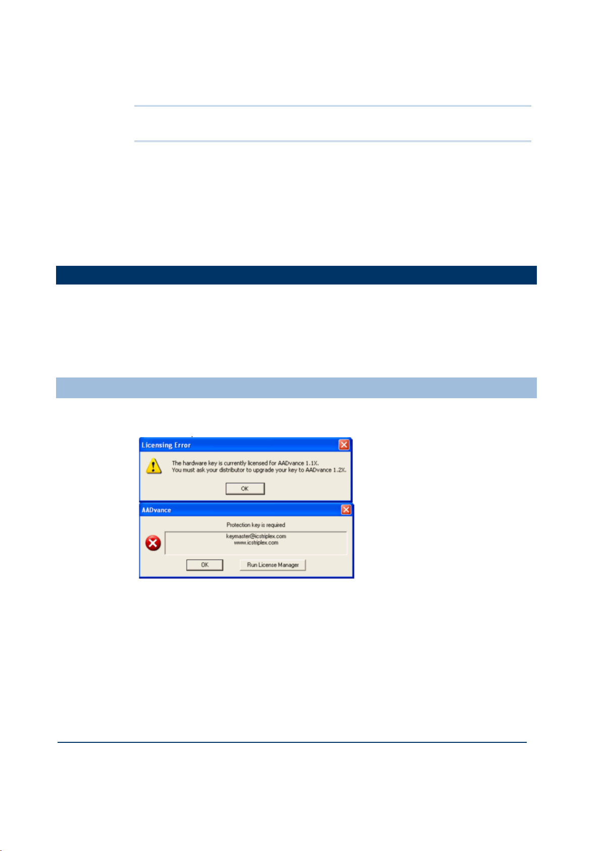
Update or Upgrade a Hardware/Software License Key
After upgrading the Workbench to Release 1.2 and opening it for the first time, a
message box will appear showing that the license needs to be upgraded.
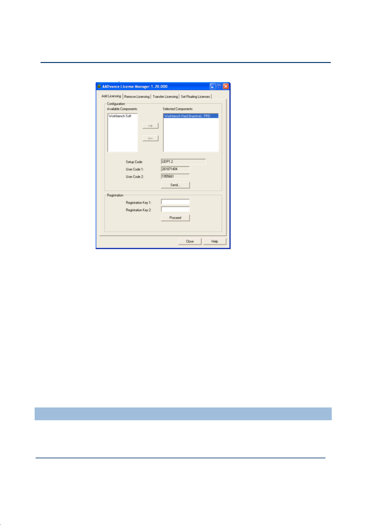
1) From the Start menu select AADvance Licensing AADvance.
The AADvance License Manager dialog box opens with the UPP1.2 Setup
Code for a software license and the UDP1.2 Setup Code for a Hardware
license and the User Codes 1 & 2.
2-8
Document: 553633
ICSTT-RM405f-EN-P
Issue 07
Configuration Guide (AADvance Controller)
2) Send the User Codes by email to keymaster@icstriplex.com.
3) If you are upgrading a hardware license key, leave it fitted.
You will be sent the Registration Keys 1 & 2.
4) Enter these keys in the two boxes and click Proceed.
Your license will be upgraded.
Multi-User Floating Hardware License
1. The Licensing Error message may not be automatically displayed, but you still need
to upgrade your license.
2. A 2-stage procedure must be followed:
first follow the above procedure to upgrade a license for a single user,
then send a second email to keymaster@icstriplex.com with the user codes
generated in the first step to create a multi-user license.
Using a Floating License Server
You can set up a networked PC as a server to provide floating AADvance licenses to
workstations on the same network. You can also set up a secondary server to provide
additional floating licenses or an alternative floating license source.
 Loading...