


RFX8210
RFX8220
RFX8230
RFX
SOURCE UNITS INSTALLATION & OPERATION

Dear Customer,
Congratulations on your purchase of the world’s finest brand of car audio source units. At Rockford Fosgate we are committed to musical reproduction at its best, and we are pleased you chose our product. Through years of engineering expertise, hand craftsmanship and critical testing procedures, we have created a wide range of products that reproduce music with all the clarity and richness you deserve.
For maximum performance we recommend you have your new Rockford Fosgate product installed by an Authorized Rockford Fosgate Dealer, as we provide specialized training through Rockford Technical Training Institute (RTTI). Please read your warranty and retain your receipt and original carton for possible future use.
To add the finishing touch to your new Rockford Fosgate image order your Rockford accessories, which include everything from T-shirts and jackets to hats and sunglasses.
To get a free brochure on Rockford Fosgate products and Rockford accessories, in the U.S. call 480-967-3565 or FAX 480-967-8132. For all other countries, call +001-480-967-3565 or FAX +001-480-967-8132.
PRACTICE SAFE SOUND™
Continuous exposure to sound pressure levels over 100dB may cause permanent hearing loss. High powered autosound systems may produce sound pressure levels well over 130dB. Use common sense and practice safe sound.
If, after reading your manual, you still have questions regarding this product, we recommend that you see your Rockford Fosgate dealer. If you need further assistance, you can call us direct at 1-800-669-9899. Be sure to have your serial number, model number and date of purchase available when you call.
The serial number can be found on the outside of the box. Please record it in the space provided below as your permanent record. This will serve as verification of your factory warranty and may become useful in recovering your source unit if it is ever stolen.
Serial Number: ______________________________
Model Number: _____________________________
SPECIFICATIONS
General
Operating Voltage
Standby Current
Operating Temperature
Dynamic Power Rating (IHF-202 Standard) per channel into a 4Ω load
RMS continuous power per channel, all channels driven into a 4Ω load from 20-20,000Hz with less than 0.1% Total Harmonic Distortion (THD)
Speaker Impedance Preamp Output Voltage
Sum Preamp Output Voltage* Preamp Output Impedance Equalization
IR Receiver Eye Range
Overall Dimensions (with trim-ring)
+10.8V – +16.0V DC 5mA Max
-30˚C to +70˚C (Receiver) -10˚C to +65˚C (CD Player)
40 watts x 4
(8210/8220/8230)
25 watts x 4
(8210/8220/8230)
4Ω – 8Ω
2.4VRMS @ 0.1% THD 2.4VRMS @ 0.1% THD <100Ω
Bass: ±10dB @ 60Hz Treble: ±8dB @ 15kHz
±45˚ off axis
2-9/32"(H) x 7-13/32"(W) x 7-1/4"(D) (58mm x 188mm x 183.7mm)
Nosepiece Dimensions (without trim-ring) 1-27/32"(H) x 6-3/4"(W) x 13/16"(D) (46.5mm x 171.5mm x 20.2mm)
Weight |
|
8210 |
3.13lbs (1.42kg) |
8220 |
3.18lbs (1.44kg) |
8230 |
3.20lbs (1.45kg) |
*Feature available on RFX8220 & RFX8230 only
– 1 –

FM Tuner
Tuning Range |
|
Americas |
87.5 ~ 107.9MHz (200kHz spacing) |
Eur/Aus |
87.5 ~ 108MHz (50kHz spacing) |
Frequency Response |
30Hz – 12kHz |
Usable Sensitivity |
10dB (S/N 30dB) |
IF Rejection |
90dB |
Image Rejection |
50dB |
Signal-to-Noise Ratio |
60dB |
Distortion |
< 0.5% |
Channel Separation |
≥ 25dB @ 1kHz |
Suppression |
35dB |
AM Tuner
Tuning Range |
|
|
Americas |
530 |
~ 1710kHz (10kHz spacing) |
Eur/Aus |
522 |
~ 1620kHz (9kHz spacing) |
Sensitivity |
20dBf max @ 10dB sensitivity |
|
-6dB Bandwidth |
5kHz min – 12kHz max |
|
CD Player
Compatible Discs |
5" or 3" |
Frequency Response |
20Hz – 20kHz (±3dB) |
Signal-to-Noise Ratio |
>90dB (preamp output |
|
w/ 22kHz LP filter) |
Distortion |
<0.5% |
Channel Separation |
86dB (preamp output |
|
w/ 22kHz LP filter) |
Dynamic Range |
100dB |
IR Remote
(optional with RFX8210)
Operation Voltage |
+3V DC |
Transmitting Range |
20 ft (variable in sunlight) |
Battery Replacement |
(1) CR2025 +3V Lithium |
Dimensions |
3-3/8"(H) x 2-1/8"(W) x 9/32"(D) |
|
(85.6mm x 54mm x 7mm) |
TABLE OF CONTENTS
Specifications . . . . . . . . . . . . . . . . . . . . . . . . . . . . . . . . . . . . . . . . . . . 1
Introduction . . . . . . . . . . . . . . . . . . . . . . . . . . . . . . . . . . . . . . . . . . . . 4
Accessory Pack . . . . . . . . . . . . . . . . . . . . . . . . . . . . . . . . . . . . . . . . . . 4
Precautions . . . . . . . . . . . . . . . . . . . . . . . . . . . . . . . . . . . . . . . . . . . . . 5
“Quick Look” Features Matrix . . . . . . . . . . . . . . . . . . . . . . . . . . . . . . . 7
Source Unit Design Features . . . . . . . . . . . . . . . . . . . . . . . . . . . . . . . . 9
IR Remote Design Features. . . . . . . . . . . . . . . . . . . . . . . . . . . . . . . . . 12
Installation Considerations . . . . . . . . . . . . . . . . . . . . . . . . . . . . . . . . . 14
Source Unit Mounting Locations . . . . . . . . . . . . . . . . . . . . . . . . . . . . 15
Wiring the System . . . . . . . . . . . . . . . . . . . . . . . . . . . . . . . . . . . . . . . 16
Installation . . . . . . . . . . . . . . . . . . . . . . . . . . . . . . . . . . . . . . . . . . . . 18
Basic Operation. . . . . . . . . . . . . . . . . . . . . . . . . . . . . . . . . . . . . . . . . 21
Tuner Operation . . . . . . . . . . . . . . . . . . . . . . . . . . . . . . . . . . . . . . . . 29
CD Player / CD Changer Operation . . . . . . . . . . . . . . . . . . . . . . . . . . 33
CD Changer Operation . . . . . . . . . . . . . . . . . . . . . . . . . . . . . . . . . . . 41
Auxilliary Audio Operation . . . . . . . . . . . . . . . . . . . . . . . . . . . . . . . . 45
IR Remote Operation . . . . . . . . . . . . . . . . . . . . . . . . . . . . . . . . . . . . . 46
Troubleshooting . . . . . . . . . . . . . . . . . . . . . . . . . . . . . . . . . . . . . . . . . 61
Warranty Information. . . . . . . . . . . . . . . . . . . . . . . . . . . . . . . . . . . . . 68
GETTING STARTED
Welcome to Rockford Fosgate! This manual is designed to provide information for the owner, salesperson and installer. For those of you who want quick information on how to install this product, please turn to the Installation Section of this manual. Other information can be located by using the Table of Contents. We, at Rockford Fosgate, have worked very hard to make sure all the information in this manual is current. But, as we are constantly finding new ways to improve our product, this information is subject to change without notice.
NOTE: This manual uses abbreviations for the following terms:
TUNER = AM/FM Radio Tuner
CDP = In-Dash CD Player
CDX = CD Changer (optional)
AUX = External Auxiliary Input (RFX8230 only)
– 2 – |
– 3 – |

INTRODUCTION
Rockford Fosgate optimizes vicious features in the RFX source units for use in high performance car audio systems. A great tuner, a high performance CD player, and controls pioneered by Rockford Fosgate give you total control of your audio system!
The following sections contain information on the features, installation, and operation for the 8210, 8220, & 8230 source units. For comparisons within the RFX line, refer to the “Quick Look” feature chart in this manual. For long term reliability of your new Rockford Fosgate source unit, please read the Precautions section on the next page.
ACCESSORY PACK
RFX8210 |
RFX8220 |
||
Installation & Operation Manual |
Installation & Operation Manual |
||
(1) |
Mounting Sleeve |
(1) |
Mounting Sleeve |
(1) |
Backstrap |
(1) |
Backstrap |
(2) |
Chassis Release Keys |
(2) |
Chassis Release Keys |
(1) |
Hardware Package |
(1) |
Hardware Package |
(1) |
8210/8220 16-pin Power |
(1) |
8810/8220 16-pin Power |
|
Harness |
|
Harness |
(1) |
Faceplate Case |
(1) |
Faceplate Case |
|
|
(1) |
IR Remote Control |
RFX8230
Installation & Operation Manual
(1)Mounting Sleeve
(1)Backstrap
(2)Chassis Release Keys
(1)Hardware Package
(1)RFX8230 16-pin Power/Aux-In Harness
(1)Faceplate Case
(1)IR Remote Control
PRECAUTIONS
Source Unit & Optional CD Changer
Operating Temperature
Be sure the temperature inside the vehicle is between –10° C and +65° C (+14° F and +149°F). DO NOT play a disc if the temperature is higher or lower than the operating range.
Moisture Condensation
The CD playback may waver due to condensation. If this occurs, remove the disc from the source unit and wait approximately an hour for the moisture to evaporate.
Environment Exposure
DO NOT expose the Source Unit or optional CD Changer to any of the following: direct sun and heat, high humidity, excessive dust, excessive vibration and rain or water.
Handling the Detachable Faceplate
DO NOT drop or cause shock to the faceplate as serious damage may occur. Protect the faceplate by storing it in the supplied carrying case.
Avoid Mechanical Malfunction
DO NOT grab a disc while it is being automatically loaded into the source unit. Doing this may cause serious damage to the playback mechanism.
– 4 – |
– 5 – |

Compact Discs
Disc Handling and Care
DO NOT touch the playing side (opposite of label side) of the disc. When handling the disc, only the outer edges or center hole of the disc should be touched. DO NOT affix any sticker or label to the disc. DO NOT apply vinyl record spray, anti-static agent, acetone, or any other volatile chemicals to the disc.
Damaged Disc
DO NOT play a cracked, warped or damaged disc. Doing this may cause serious damage to the playback mechanism.
New Discs
The CD player will eject discs that have either been inserted incorrectly or have irregular surfaces. If a new disc is ejected after loading, feel around the outer edge of the CD and its center hole. Any small burrs or irregularities could inhibit proper loading of the disc. To remove the burrs, rub the inside edge of the hole and outside edge of the disc with an object such as a ball point pen.
IR Remote (RFX8220/RFX8230)
Environment Exposure
DO NOT expose the IR Remote to any of the following: direct sun and heat, high humidity and rain or water.
Handling the IR Remote
DO NOT drop or cause shock to the IR Remote as serious damage may occur.
QUICK LOOK FEATURES |
RFX8210 |
RFX8220 |
RFX8230 |
RFX8810 |
|
|
|
|
|
Control/Lighting/Appearance |
|
|
|
|
|
|
|
|
|
Detachable Faceplate |
X |
X |
X |
- |
|
|
|
|
|
ISO Din Mounting |
X |
X |
X |
- |
w/ Removable Trim Panel |
|
|
|
|
|
|
|
|
|
Multi Function Volume Knob |
X |
X |
X |
- |
|
|
|
|
|
Any Button Wake-Up |
X |
X |
X |
- |
|
|
|
|
|
Time of Day Clock |
X |
X |
X |
- |
|
|
|
|
|
Programmable Default Display |
X |
X |
X |
- |
|
|
|
|
|
Negative Image LCD Display |
X |
X |
X |
- |
|
|
|
|
|
IR Remote Compatible |
X |
X |
X |
- |
|
|
|
|
|
Illumination “ON” w/ Ignition |
X |
X |
X |
- |
|
|
|
|
|
Display Back Lighting |
Green |
Green/Amber |
Green/Amber |
- |
|
|
|
|
|
IR Remote Included |
- |
X |
X |
- |
|
|
|
|
|
Tuner |
|
|
|
|
|
|
|
|
|
World Wide Tuning |
X |
X |
X |
- |
|
|
|
|
|
AM mono/FM stereo |
X |
X |
X |
- |
|
|
|
|
|
FM Noise Blanker |
X |
X |
X |
- |
|
|
|
|
|
Auto Blend / Roll Off |
X |
X |
X |
- |
|
|
|
|
|
Multi-Path Interference Rejection |
X |
X |
X |
- |
|
|
|
|
|
12 AM / 18 FM Presets |
X |
X |
X |
- |
|
|
|
|
|
AM1/AM2/FM1/FM2/FM3 |
X |
X |
X |
- |
|
|
|
|
|
Preset Scan |
X |
X |
X |
- |
|
|
|
|
|
Auto Store Non-Volatile Presets |
X |
X |
X |
- |
|
|
|
|
|
AM/FM Seek |
X |
X |
X |
- |
|
|
|
|
|
AM/FM Manual Tuning |
X |
X |
X |
- |
|
|
|
|
|
AM/FM Scan |
X |
X |
X |
- |
|
|
|
|
|
Pause (MUTE) |
X |
X |
X |
- |
|
|
|
|
|
Programmable Station Titles |
- |
X |
X |
- |
|
|
|
|
|
CD Player |
|
|
|
|
|
|
|
|
|
Dual 1-bit D/A Converters |
X |
X |
X |
- |
w/ 8 x oversampling |
|
|
|
|
|
|
|
|
|
Ignition Off Disc Load/Eject |
X |
X |
X |
- |
|
|
|
|
|
Repeat Mode |
X |
X |
X |
- |
|
|
|
|
|
Random Play (CD) |
X |
X |
X |
- |
|
|
|
|
|
Track Scan |
X |
X |
X |
- |
|
|
|
|
|
Fast Forward/Reverse |
X |
X |
X |
- |
|
|
|
|
|
– 6 – |
– 7 – |
QUICK LOOK FEATURES |
RFX8210 |
RFX8220 |
RFX8230 |
RFX8810 |
|
|
|
|
|
Next/Previous Track |
X |
X |
X |
- |
|
|
|
|
|
Programmable Eject Mute Off |
X |
X |
X |
- |
|
|
|
|
|
Insert Disc Power Up/Play |
X |
X |
X |
- |
Pause/Resume Play |
X |
X |
X |
- |
|
|
|
|
|
Programmable Disc Titles |
- |
- |
X |
- |
|
|
|
|
|
Pre Amp/Power |
|
|
|
|
|
|
|
|
|
Source Tone Memory |
X |
X |
X |
- |
|
|
|
|
|
Switchable Loudness |
X |
X |
X |
- |
|
|
|
|
|
Electronic Volume, Tone, Balance |
X |
X |
X |
- |
|
|
|
|
|
Internal Audio Amplifier |
25 watts RMS |
25 watts RMS |
25 watts RMS |
- |
|
(40 max) x 4 |
(40 max) x 4 |
(40 max) x 4 |
|
|
|
|
|
|
Number of Preouts |
4 RCA |
6 RCA |
6 RCA |
- |
|
|
|
|
|
Front/Rear Sum Preout (#5 & #6) |
- |
X |
X |
- |
|
|
|
|
|
Preout Voltage |
2.4 volts RMS |
2.4 volts RMS |
2.4 volts RMS |
- |
|
|
|
|
|
Low Source Impedance |
< 100Ω |
< 100Ω |
< 100Ω |
- |
|
|
|
|
|
External Audio Inputs (AUX-IN) |
- |
- |
X |
- |
|
|
|
|
|
Remote Functions |
IR optional |
IR included |
IR included |
- |
|
|
|
|
|
Tuner, CD and Changer Mode |
X |
X |
X |
X |
|
|
|
|
|
Volume Up/Down |
X |
X |
X |
X |
|
|
|
|
|
Seek (Track) Up/Down |
X |
X |
X |
X |
|
|
|
|
|
Fast Forward/Reverse |
X |
X |
X |
X |
|
|
|
|
|
Tune (Disc) Up/Down |
X |
X |
X |
X |
|
|
|
|
|
Pause/Resume Play |
X |
X |
X |
X |
|
|
|
|
|
Direct Preset Access |
X |
X |
X |
- |
|
|
|
|
|
Direct Track Access |
X |
X |
X |
X |
|
|
|
|
|
Direct Disc Access |
- |
- |
- |
X |
|
|
|
|
|
CD Changer Control |
|
|
|
|
|
|
|
|
|
Dual 1-bit D/A Converters |
X |
X |
X |
X |
w/ 8 x oversampling |
|
|
|
|
|
|
|
|
|
CD Changer Controller |
X |
X |
X |
- |
|
|
|
|
|
Changer Repeat Mode |
X |
X |
X |
X |
|
|
|
|
|
Changer Random Play |
X |
X |
X |
X |
|
|
|
|
|
Pause/Resume Play |
X |
X |
X |
X |
|
|
|
|
|
Changer Track Scan |
X |
X |
X |
X |
|
|
|
|
|
Changer Disc Scan |
X |
X |
X |
X |
|
|
|
|
|
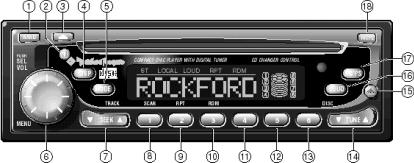
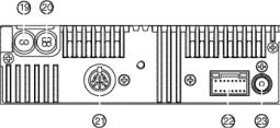
Source Unit Design
1.BAND – Selects which bank of tuner presets (FM1/FM2/ FM3/AM1/AM2) should be active.
2.POWER – Turns the source unit on and off.
3.EJECT – Ejects the CD from the in-dash CD player.
4.DISP – Switches the source unit between the clock and the currently selected mode (TUNER/CDP/CDX/AUX*).
5.MODE – Selects between TUNER/CDP/CDX/AUX* modes.
6.MENU – Selects between Volume/Bass/Treble/Balance/ Fader/Sum** modes.
7.SEEK/TRACK – Selects the previous/next radio station in TUNER mode and selects the previous/next track in CDP/CDX mode.
8.PRESET 1/SCAN – Selects radio preset #1 in TUNER mode and scans each track on the disc in CDP/CDX mode.
9.PRESET 2/RPT – Selects radio preset #2 in TUNER mode and repeats the current track in CDP/CDX mode.
*Features available on RFX8230 only
**Features available on RFX8220 & RFX8230 only
– 8 – |
– 9 – |
10.PRESET 3/RDM – Selects radio preset #3 in TUNER mode and selects tracks at random in CDP/CDX mode.
11.PRESET 4 – Selects radio preset #4 in TUNER mode.
12.PRESET 5 – Selects radio preset #5 in TUNER mode.
13.PRESET 6 – Selects radio preset #6 in TUNER mode.
14.TUNE/DISC – Manually tunes the radio station in TUNER mode and selects previous/next disc in CDX mode.
15.RELEASE – Detaches the faceplace from the source unit.
16.LOUD – Enables bass response to be boosted at low and high levels
17.AS/PS – Press and hold to store the strongest radio stations in each tuner bank in AUTO STORE mode. Momentarily press to scan each radio preset in PRESET SCAN mode.
18.MUTE – Mutes the audio in TUNER/AUX* modes and pauses the disc in CDP/CDX mode.
*Feature available on RFX8230 only
19.Sum Preamp Output** – These RCA jacks provide a lowlevel SUMMED MONO (L+R) output used to connect amplifier(s) driving subwoofers.
20.Front/Rear Preamp Output – These RCA jacks provide a low-level STEREO output used connect amplifier(s) driving front & rear speakers.
21.CD Changer Input – This 8-pin DIN is used to connect an optional RFX CD Changer to the source unit.
22.Power Connector – The 16-pin molex is used for power, speaker, and AUX* connections.
23.Antenna Input – Connects a standard male Motorola coaxial radio antenna to the source unit.
IMPORTANT: The communication BUS used in Rockford Fosgate models RFX8210/8220/8230 is used only for CD changer model RFX8810 and is not backward compatible with older RFX models. Rockford Fosgate recommends connecting only the appropriate RFX models together. Rockford Fosgate does not assume responsibility when using other manufacturers’ source units with Rockford Fosgate CD changers (or vice versa).
*Feature available on RFX8230 only
**Feature available on RFX8220 & RFX8230 only
– 10 – |
– 11 – |
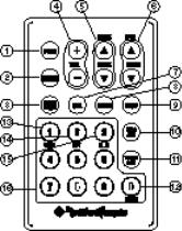
IR REMOTE DESIGN FEATURES
(RFX8210 optional accessory)
1.POWER – Turns the source unit on and off.
2.MODE – Selects between TUNER/CDP/CDX/AUX* modes.
3.MUTE – Mutes the audio in TUNER/AUX* modes and pauses the disc in CDP/CDX mode.
4.VOL – Controls Volume/Bass/Treble/Balance/Fader/Sum**
5.SEEK/TRACK – Selects the previous/next radio station in TUNER mode and selects the previous/next track in CDP/CDX mode.
6.TUNE/DISC – Manually tunes the radio station in TUNER mode and the previous/next disc in CDX mode.
7.SEL – Selects between Volume/Bass/Treble/Balance/Fader/ Sum** modes.
8.BAND – Selects which bank of tuner presets (FM1/FM2/FM3/AM1/AM2) should be active.
9.DISP – Switches the source unit between the clock and the currently selected mode (TUNER/CDP/CDX/AUX*).
10.DISC ACC – Directly accesses the desired CD in the optional CD changer.
11.TRACK ACC – Directly accesses the desired track in the indash CD player
12.AS/PS – Press and hold to store the strongest radio stations in each tuner bank in AUTO STORE mode. Momentarily press to scan each radio preset in PRESET SCAN mode.
13.SCAN – Scans each track on the disc in CDP/CDX mode.
14.RPT – Repeats the track in CD/CDX mode.
15.RDM – Selects tracks at random in CDP/CDX mode.
16.0-9 BUTTONS – Selects presets 1-6 in TUNER mode, selects tracks in CDP & CDX mode, and selects discs in CDX mode.
*Features available on RFX8230 only
**Features available on RFX8220 & RFX8230 only
– 12 – |
– 13 – |
INSTALLATION CONSIDERATIONS
The following is a list of tools needed for installing the Source Unit:
Volt/Ohm Meter |
#2 Phillips screwdriver |
Wire strippers |
Battery post wrench |
Wire crimpers |
Soldering iron |
Wire cutters |
Solder |
1/8" diameter heatshrink tubing |
Heat gun |
This section focuses on some of the vehicle considerations for installing your new Source Unit. Pre-planning your system layout and best wiring routes will save installation time. When deciding on the layout of your new system, be sure that each component will be easily accessible for making adjustments.
Before beginning any installation, be sure to follow these simple rules:
1.Be sure to carefully read and understand the instructions before attempting to install the Source Unit.
2.For safety, disconnect the negative lead from the battery prior to beginning the installation.
3.For easier assembly, we suggest you run all wires prior to mounting your Source Unit in place.
4.Route all of the RCA cables close together and away from any high current wires.
5.Use high quality connectors for a reliable installation and to minimize signal or power loss.
6.Think before you drill! Be careful not to cut or drill into gas tanks, fuel lines, brake or hydraulic lines, vacuum lines or electrical wiring when working on any vehicle.
7.Never run wires underneath the vehicle. Running the wires inside the vehicle provides the best protection.
8.Avoid running wires over or through sharp edges. Use rubber or plastic grommets to protect any wires routed through metal, especially the firewall.
9.ALWAYS protect the battery and electrical system from damage with proper fusing. Install the appropriate fuseholder and fuse on the +12V power wire within 18” (45.7 cm) of the battery terminal.
10.When grounding to the chassis of the vehicle, scrape all paint from the metal to ensure a good, clean ground connection. Grounding connections should be as short as possible and always be connected to metal that is welded to the main body, or chassis, of the vehicle.
SOURCE UNIT MOUNTING LOCATIONS
The mounting position of your source unit will have a great effect on the performance of your in-dash CD Player. The source unit can be installed in a wide range of operating locations. However, care should be taken to ensure optimum performance.
Engine Compartment
Mounting the source unit in the engine compartment will void your warranty. Doing so will not only cause severe damage to your new source unit...but will immediately promote you to “customer of the month” in our technical support department.
Instrument Panel
Mounting the source unit in the instrument panel provides optimum access. The source unit should be securely mounted using the “Standard Mount” or “ISO Mount” method to ensure optimum CD Player performance.
Center Console
Mounting the source unit in the center console provides optimum access. Be sure the installation does not interfere with the operation of the gear shift or parking brake. The source unit should have a mounting angle within ±20° from horizontal.
Glove Box
Mounting the source unit in the glove box is adequate, but does not provide easy access. Glove box mounting should only be done if “Instrument Panel” or ”Center Console,” mounting is not acceptable (i.e., maintaining integrity of older vehicles with metal dashboards.) The source unit should be mounted within ±20° from horizontal.
Under Dash
Mounting the source unit under the dash is adequate, but does not provide easy access. Under dash mounting should only be done if “Instrument Panel,” ”Center Console” or ”Glove Box” mounting is not acceptable. Mount the source unit off to the side of the driver's area to reduce interference with the parking brake, gear shift, or operating pedals. The source unit should be mounted within ±20° from horizontal.
– 14 – |
– 15 – |
WIRING THE SYSTEM
NOTICE: If you do not feel comfortable with wiring your new source unit, please see your local Authorized Rockford Fosgate Dealer for installation.
•For safety, disconnect the negative lead from the battery prior to beginning the installation.
1.Install the 16-Pin Power Harness by connecting the corresponding wires to the electrical and audio system. Solder and heat shrink all connections for a reliable installation. For each connection, cut a 1" piece of heat shrink tubing and slide over one of the wires. Strip each wire 3/8" then twist together and solder. Slide the tubing over the connection and shrink the tubing with a hot air gun until no bare wire is exposed.
2.Connect the BLACK wire to chassis ground. Prepare the chassis ground by scraping any paint from the metal surface and thoroughly clean the area of all dirt and grease. Strip the end of the wire and attach a ring connector. Fasten the wire to the chassis using a non-anodized screw and star washer.
3.Connect the YELLOW wire to a source of constant +12V (for retaining memory on user-programmed functions). Connect the Yellow wire to a constant +12 volt positive source. The source should always have +12V, even when the ignition is off and the car is not running.
4.Connect the RED wire (Ignition) to a source of switched +12V (is on only when ignition key is in “accessory” or “run”).
Connect the RED wire to a switched +12 volt positive source. The switched signal is usually taken from the ACC (accessory) position of the ignition. If the vehicle does not have an ACC position, connect the wire to the switched ON position of the ignition. The current consumption through this wire is negligible.
5.Connect the LT. BLUE wire to the “Remote Turn-On” leads of the amplifier(s). This will turn-on the external amplifiers when the source unit is powered on.
6.Connect the BLUE/RED wire to the “Power Antenna” lead. This will raise a fully automatic antenna when the source unit is powered on.
7.Connect the B+, GND and Remote Turn on Wires on the 16 pin harness according to the Installation Reference Sheet.
8.Connect the AUX* to the external audio source (this inserts the audio before the volume control on the source unit). The maximum un-clipped input voltage this circuit can accept is 2.4V RMS.
Connect the Speaker Wires (if external amplifiers are not used) to the corresponding speaker leads by soldering and heat shrinking all connections for a reliable installation. If only one pair of speakers is utilized in the system, use only the FRONT speaker leads and heat shrink the unused REAR leads to prevent from shorting out. Be sure to maintain speaker polarity. DO NOT chassis ground any speaker leads as unstable operation may result.
9.Install the Preamp Output Harness (if external amplifiers will be used) by plugging the RCA cables into the corresponding extension RCAs that feed the input of the amplifiers. Be sure to route the signal cables away from any high current wires to prevent coupling noise from radiated electrical fields into the audio signal.
The FRONT RCAs connect to the Front speaker's amplifier. The REAR RCAs connect to the Rear speaker's amplifier. The SUM** RCAs connect to the Subwoofer amplifier.
10.Connect the CD Changer (optional) by plugging the 8-pin DIN cable into the connector located at the rear of the source unit.
11.Connect the Antenna by plugging the antenna cable into the connector located at the rear of the source unit. Be sure the antenna is securely grounded to the vehicle for proper radio reception.
*Feature available on RFX8230 only
**Feature available on RFX8220 & RFX8230 only
– 16 – |
– 17 – |

SOURCE UNIT INSTALLATION
Source Unit Mounting Angle
•Mount the Source Unit as close to horizontal as possible for optimum CD Player performance
•Mounting Angles up to ±20˚ from horizontal can be accommodated
Using the Installation Sleeve - Standard Mount
•Mount the Installation Sleeve into a secure instrument panel
•Bend Tabs on the installation sleeve which correspond to the chart above
•Bend Appropriate Tabs on all sides of the mounting sleeve (Top, Bottom, Left & Right)
Installing the Source Unit – Standard Mount
CAUTION: Installation sleeve should be installed using the appropriate tabs (refer to previous page)
•Install Source Unit by sliding unit into installation sleeve until it clicks into place
•Mount Backstrap securely behind the instrument panel to prevent source unit vibration
•Backstrap Screw should be 6mm max (use supplied screw)
•Connect Antenna to antenna jack on rear of source unit
•Antenna Ground should read less than 0.05Ω between antenna and chassis ground
Installing the Source Unit – ISO-DIN Mount
•Remove Trim Piece and Installation Sleeve from source unit
•Factory Bracket should align with two mounting holes on each side of source unit
•ISO Screws should be 6mm max (use supplied screws)
•Connect Antenna to antenna jack on rear of source unit
•Antenna Ground should read less than 0.05Ω between antenna and chassis ground
•Install Source Unit into instrument panel
– 18 – |
– 19 – |
Un-Installing the Source Unit – Standard Mount
•Disconnect Backstrap from rear of radio (if used)
•Insert Release Keys into left and right sides of source unit to disengage locks
•Remove Source Unit from installation sleeve with release keys
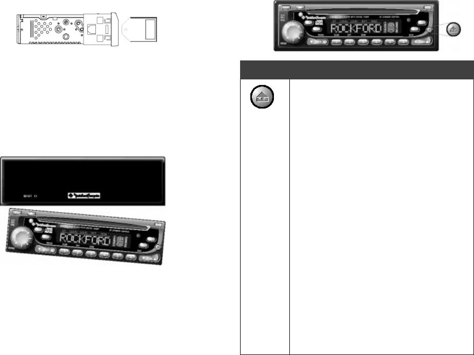
Reset Button
•Remove Faceplate from source unit
•Press Reset Button if source unit gets jammed during operation
BASIC OPERATION
DETACHABLE FACEPLATE
The faceplate is detachable as an anti-theft deterrent system.
Attach the Faceplate
1.Insert left side of faceplate into the housing.
2.Press faceplate into housing until it clicks.
Remove the Faceplate
1.Press the “^” button
2.Grasp the right side of the faceplate and remove it from the housing
CAUTION: Store the faceplate in its carrying case to prevent damage
– 20 – |
– 21 – |
 Loading...