


t r a n s • a n a
®
c |
a |
r |
a |
u |
d |
i |
t r a n s • a n a
®
|
|
|
|
|
|
|
|
|
s |
|
|
|
|
|
|
|
|
|
|
|
|
|
|
|
|
|
|
c |
|
|
|
|
|
|
|
|
i |
|
|
o for |
|
|
|
|
t |
|
|
||
|
|
|
a |
|
|
|
|||
|
|
n |
|
|
|
|
|||
|
a |
|
|
|
|
|
|||
|
f |
|
|
|
|
|
|
||
|
|
|
|
|
|
|
|
||
t r a n s • a n a
t r a n s • a n a
punch
2-Channel Amplifiers
Operation & Installation
®

Dear Customer,
Congratulations on your purchase of the world's finest brand of car audio amplifiers. At Rockford Fosgate we are fanatics about musical reproduction at its best, and we are pleased you chose our product. Through years of engineering expertise, hand craftsmanship and critical testing procedures, we have created a wide range of products that reproduce music with all the clarity and richness you deserve.
For maximum performance we recommend you have your new Rockford Fosgate product installed by an Authorized Rockford Fosgate Dealer, as we provide specialized training through Rockford Technical Training Institute (RTTI). Please read your warranty and retain your receipt and original carton for possible future use.
Great product and competent installations are only a piece of the puzzle when it comes to your system. Make sure that your installer is using 100% authentic installation accessories from Connecting Punch in your installation. Connecting Punch has everything from RCA cables and speaker wire to Power line and battery connectors. Insist on it! After all, your new system deserves nothing but the best.
To add the finishing touch to your new Rockford Fosgate image order your Rockford wearables, which include everything from T-shirts and jackets to hats and sunglasses.
To get a free brochure on Rockford Fosgate products and Rockford accessories, in the U.S. call 602-967-3565 or FAX 602-967-8132. For all other countries, call +001-602- 967-3565 or FAX +001-602-967-8132.
PRACTICE SAFE SOUND™
CONTINUOUS EXPOSURE TO SOUND PRESSURE LEVELS OVER 100dB MAY CAUSE PERMANENT HEARING LOSS. HIGH POWERED AUTOSOUND SYSTEMS MAY PRODUCE SOUND PRESSURE LEVELS WELL OVER
130dB. USE COMMON SENSE AND PRACTICE SAFE SOUND.
If, after reading your manual, you still have questions regarding this product, we recommend that you see your Rockford Fosgate dealer. If you need further assistance, you can call us direct at 1-800-669-9899. Be sure to have your serial number, model number and date of purchase available when you call.
The serial number can be found on the outside of the box. Please record it in the space provided below as your permanent record. This will serve as verification of your factory warranty and may become useful in recovering your amplifier if it is ever stolen.
Serial Number: ________________________________
Model Number: ________________________________

TABLE OF CONTENTS |
|
Introduction ................................................................................................ |
1 |
Punch Amplifier Accessory Pack ................................................................... |
1 |
Technical Design Features ............................................................................ |
2 |
Design Features .......................................................................................... |
5 |
Installation Considerations ........................................................................... |
7 |
Mounting Location ...................................................................................... |
8 |
Battery and Charging .................................................................................. |
9 |
Wiring the System ....................................................................................... |
9 |
Using Passive Crossovers ........................................................................... |
12 |
Table of Component Values ........................................................................ |
13 |
Using the XCard ........................................................................................ |
14 |
Resistor Chart ........................................................................................... |
15 |
Installation ............................................................................................... |
16 |
System Diagrams ...................................................................................... |
20 |
Rockford Fosgate Accessories ..................................................................... |
24 |
Troubleshooting ........................................................................................ |
26 |
Dynamic Power Measurements ................................................................... |
29 |
Specifications ........................................................................................... |
31 |
Warranty Information ................................................................................ |
33 |
International Information ............................................................................ |
34 |
G E T T I N G S T A R T E D |
|
Welcome to Rockford Fosgate! This manual is designed to provide information for the owner, salesperson and installer. For those of you who want quick information on how to install this product, please turn to the Installation Section of this manual or refer to the icons listed below. Other information can be located by using the Table of Contents. We, at Rockford Fosgate, have worked very hard to make sure all the information in this manual is current. But, as we are constantly finding new ways to improve our product, this information is subject to change without notice.
A O |
I |
TROUBLE-S |
|
N |
|||
D |
P |
S |
H |
V |
E |
T |
O |
A |
|||
A R |
L |
O |
|
|
A |
L |
T |
N T |
A |
||
C |
I |
T |
I |
|
I |
N |
|
E O |
O |
||
D N |
N |
G |
|
Sections marked |
Sections marked |
Sections marked |
ADVANCED OPERATION |
INSTALLATION |
TROUBLESHOOTING |
include in-depth |
include “slam dunk” |
include recommendations for |
technical information |
wiring connections |
curing installation problems |

IN T R O D U C T I O N
Rockford engineers designed the Punch 55.2, 75.2, 125.2 and 225.2 amplifiers to withstand the rugged automotive environment while delivering superior sound quality in a flexible, reliable, and efficient package. TRANS•ANA is a low voltage circuit in the preamp stage of all Punch .2 amplifiers that lets the music sound crystal clear and very real, even when played at high volume levels. This is matched with TOPAZ, a unique grounding circuit used to eliminate noise problems associated with car audio systems and their installation. Flexibility is accomplished with the use of a built-in XCard. Reliability is all but guaranteed with the use of a protection circuit called NOMAD, while MOSFET and DSM (Discrete Surface Mount) technology improve amplifier efficiency. The result of these components give the Punch amplifier awesome sound quality in a “Bullet Proof” package. An explanation of these technologies, most of which are exclusively designed and patented by Rockford, are described in the Technical Design Features.
PUNCH AMPLIFIER ACCESSORY PACK
The accessory pack shipped with the Punch 2-channel amplifiers includes the mounting hardware necessary to secure the amp to the vehicle and to attach the end caps to the amplifier.
Installation & Operation Manual Punch Verification Certificate
(4) Amplifier mounting screws (#8 x 3/4" Phillips)
(6) Speaker & power connector screws (3/32" Allen)
(4) End cap mounting screws (9/64" Allen)
(1) Allen Wrench 9/64"
(1) Allen Wrench 3/32"
(1) ATC Inline Fuseholder (Punch 55.2, 75.2, 125.2)
(1) AGU Inline Fuseholder (Punch 225.2)
(1) ATC 20 Amp Fuse (Punch 55.2)
(1) ATC 30 Amp Fuse (Punch 75.2)
(1) ATC 40 Amp Fuse (Punch 125.2)
(1) AGU 50 Amp Fuse (Punch 225.2)
– 1 –

TECHNICAL DESIGN FEATURES
TRANS•ANA
(TRANSconductance Active Nodal Amplifier)
The TRANS•ANA (TRANSconductance Active Nodal Amplifier) is a circuit that allows the audio signal to pass through the amplifier at low voltage. The signal is directly level-shifted to the fixed high voltage rails via a pair of driver transistors. Signal linearity is assured by an active node formed by the drive transistors at ultrasonic frequencies. This allows amplifier performance similar to trans•nova which is highly stable and linear while utilizing the advantages of a non-floating power supply.
THE RESULT: An extended frequency bandwidth accurately supplied to the output stages of the amplifier.
MEHSA (Maximum Efficiency Heat Sink Application)
The MEHSA (Maximum Efficiency Heat-Sink Application) is a proprietary process that yields up to 5 times better heat transfer than traditional FET mounting techniques using the exact same components. A multi-layer insulated metal substrate operating with minimal thermal resistance spreads heat both downward & outward to quickly dissipate heat from each device across the heat sink. This process combined with our DSM technology and MOSFET devices allow us to squeeze more watts per cubic inch from every output device as well as provide consistent thermal stability.
THE RESULT: Optimized power output, enhanced thermal stability, and maximum component reliability.
TOPAZ (Tracking Operation Pre-Amplifier Zone)
The TOPAZ (Tracking Operation Pre-Amplifier Zone) circuitry solves ground loop noise problems common to automotive amplifier design. This innovative new development allows vastly improved isolation of the input signal grounds from the power supply ground of the amplifier. This is accomplished by allowing the source unit to control the potential “environment” of the entire input structure or “zone” of the amplifier. This process improves the noise rejection of the amplifier by 30-40dB – an astounding 30-100 times better than amplifiers without TOPAZ.
THE RESULT: Elimination of troublesome ground loop noise between source and amplifier.
– 2 –

DSM (Discrete Surface Mount) Technology
The DSM (Discrete Surface Mount) manufacturing process combines the advantages of both discrete components and integrated circuitry. Rockford Fosgate is the only American amplifier manufacturer to have invested millions into this process. DSM components differ from conventional discrete components in different ways. They are more compact, more rugged, and they efficiently dissipate generated heat. Using them wherever appropriate allows the advantages associated with discrete circuitry to be retained while also providing room for both highly advanced processing features and generous PC board copper paths where needed. Their short lead-out structures allow maximum audio performance and highest signal-to-noise ratios to be obtained in amplifiers of desirable package size without resorting to “ampli- fier-on-a-chip” shortcuts. These advantages are shown below in Figure 1.
THE RESULT: Fewer connections, improved reliability, shorter signal paths, superior signal-to-noise ratio and awesome sonic performance.
|
Figure 1 |
|
|
Component |
|
|
|
||||||||||
|
|
|
|
|
|
||||||||||||
|
PC |
|
|
|
|
|
Solder |
|
|
Solder |
|
||||||
|
|
|
|
|
|
|
|
||||||||||
|
|
|
|
|
|
|
|
|
|
PC |
|
||||||
|
Board |
|
|
|
|
|
|
|
|
|
|
|
|
Board |
|
||
|
|
|
|
|
|
|
|
|
|
|
|
|
|
||||
|
|
|
|
|
|
|
|
|
|
|
|
|
|
||||
|
|
|
|
|
|
|
|
|
|
|
|
|
|
|
|
|
|
|
|
|
|
|
|
|
|
|
|
|
|
|
|
|
|
|
|
|
|
|
|
|
Thru-Hole |
|
|
Surface Mount |
|
|
|
||||||
|
|
|
|
|
|
|
|
|
|
|
|
|
|
|
|
|
|
|
|
|
|
|
|
|
|
|
|
|
|
|
|
|
|
|
|
XCard (Internal Crossover)
The Punch amplifiers utilize internal active crossovers. These crossovers have many performance advantages such as using discrete components for exact frequency adjustments which are far superior to potentiometers. Additionally, the XCard can be configured for high-pass, low-pass and full range operation. With slight modifications, many crossover frequencies and slope configurations can be achieved.
THE RESULT: Increased system design flexibility with a precise electronic crossover without the limitations of conventional potentiometer designs.
– 3 –

MOSFET Devices
Rockford Fosgate is one of the few manufacturers in the sound community to utilize MOSFET devices in both the power supply and the output stages. MOSFET (Metal Oxide Semiconductor Field Effect Transistor) devices offer several important inherent advantages over the 30 year old technology of bipolar design. These advantages include: thermal stability, switching speed, ultra low output impedance and wider bandwidth linearity. In addition, MOSFETs operate very similarly to vacuum tubes in that they are more linear than bi-polar transistors. However, MOSFETs can deliver the midrange clarity without the limitations of transient response and high frequency phase shifting normally associated with tube operation.
THE RESULT: Operational characteristics similar to vacuum tubes without the performance limitations of tube design.
NOMAD (NOn-Multiplying Advanced Decision)
The Punch amplifiers use an analog computer process to maximize safe output power under all operating conditions. The innovative NOMAD (NOn- Multiplying Advanced Decision) system is the most sophisticated version of this technique ever used, bringing previously unavailable levels of accuracy, stability, temperature immunity and reliability to this critical process. NOMAD makes advanced decisions based on device voltages to precisely control the awesome levels of current available in the output MOSFETs to safe values – but only when absolutely needed.
THE RESULT: Extremely fast protection system that always protects the amplifier and never degrades the sound.
Punch EQ
The Punch EQ helps correct for acoustical deficiencies in the listening environment. Two unique potentiometers that control bass and treble compensate for the response errors present in most car environments. Unlike conventional tone controls, Punch EQ corrects the specific problems of poor low bass response and high frequency rolloff.
THE RESULT: Full range sound without excessive boost in areas where it is not needed.
– 4 –
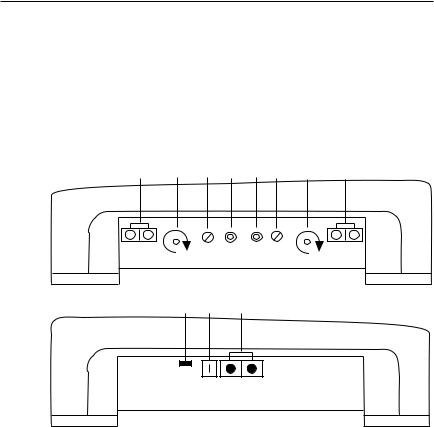
DESIGN FEATURES
1.Cast Aluminum Heatsink – The cast aluminum heatsink of the Punch amplifier dissipates heat generated by the amplifier's circuitry. The inherent advantage of casting provides a 30% improvement of cooling over conventional extrusion heatsink designs.
2.End Caps – The unique end caps conceal the wiring and input cables, giving the amplifier a clean “stealth” look.
3 |
8 |
7 |
6 |
6 |
7 |
8 |
3 |
Speaker |
|
|
|
|
Speaker |
+ L – |
Left |
Left |
Right |
Right |
+ R – |
Treble |
Gain |
Input |
Input |
Gain |
Bass |
9 5 4
LED
REM B+ GND
3.Speaker Terminals – The heavy duty, gold-plated terminal block connectors (+ and –) will accept wire sizes from 8 AWG to 18 AWG. These gold-plated connectors are immune to corrosion that can cause signal deterioration.
4.Power Terminals – The power and ground connectors on the Punch amplifier are gold-plated and will accommodate up to 8 AWG wire maximizing the input current capability of the amplifier.
5.REM Terminal – This gold-plated spade terminal is used for the auto power/remote turn on of the Punch amplifier.
6.RCA Input Jacks – The industry standard RCA jacks provide easy connections for signal level input. They are gold-plated to resist the signal degradation caused by corrosion.
–5 –
7.Input Sensitivity Controls – The input level controls are preset to match the output of most source units. They can be adjusted to match output levels from a variety of source units.
8.Punch Equalization Controls – The Punch EQ helps correct for acoustical deficiencies in the listening environment. The Bass control allows a narrow band adjustment of up to 18dB centered at 45Hz. The Treble control is a wide band hinged adjustment with a maximum of 12dB at 20kHz. The Punch EQ can be bypassed by turning the controls to their minimum or counterclockwise position.
9.LED Power Indicator – The LED illuminates when the unit is turned on.
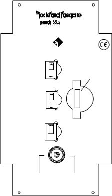
10.XCard (Internal Crossover) – This built-in crossover card is configurable for a multitude of operating frequencies. The orientation of the card in its socket determines the function of high-pass, low-pass, or full range operation.
®
A M P L I F I E R
27.5 Watts RMS continuous power per channel into 4 Ohms with less than 0.08% Total Harmonic Distortion from 20-20kHz
®
ROCKFORD CORPORATION
MADE IN THE USA
High-Pass
HP |
|
LP |
10 |
|
|
Low-Pass |
|
LP |
|
HP |
|
Full Range |
|
FULL |
|
+ |
– |
Do Not Chassis |
|
Ground Any Speaker. |
|
L+ |
R– |
For Bridged Mono Wiring
Connect 4Ω mono woofer + to L+ of amplifier and mono woofer – to R– of amplifier. Amplifier will operate mono/stereo simultaneously.
– 6 –

INSTALLATION CONSIDERATIONS
The following is a list of tools you will need for installing the Punch amplifier:
Allen wrenches 9/64" & 3/32" (included) |
Voltmeter |
Wire strippers |
Battery post wrench |
Electric hand drill w/assorted bits |
Wire cutters |
17' (518.16cm) Red Power Wire |
Assorted connectors |
12' (365.76cm) Remote Turn-On Wire |
Wire crimpers |
1.5' (45.72cm) Black Grounding Wire |
|
This section focuses on some of the vehicle considerations for installing your new Punch amplifier. Checking your battery and present sound system, as well as pre-planning your system layout and best wiring routes will save installation time. When deciding how to lay out your new system, be sure that each component will be easily accessible for making adjustments.
Before beginning any installation, be sure to follow these simple rules:
1.Be sure to carefully read and understand the instructions before attempting to install the amplifier.
2.For safety, disconnect the negative lead from the battery prior to beginning the installation.
3.For easier assembly, we suggest you run all wires prior to mounting your amplifier in place.
4.Route all of the RCA cables close together and away from any high current wires.
5.Use high quality connectors for a reliable installation and to minimize signal or power loss.
6.Think before you drill! Be careful not to cut or drill into gas tanks, fuel lines, brake or hydraulic lines, vacuum lines or electrical wiring when working on any vehicle.
7.Never run wires underneath the vehicle. Running the wires inside the vehicle provides the best protection.
8.Avoid running wires over or through sharp edges. Use rubber or plastic grommets to protect any wires routed through metal, especially the firewall.
9.ALWAYS protect the battery and electrical system from damage with proper fusing. Install a fuseholder and appropriate fuse on the +12V power wire within 18” (45.7 cm) of the battery terminal.
10.When grounding to the chassis of the vehicle, scrape all paint from the metal to ensure a good, clean ground connection. Grounding connections should be as short as possible and always be connected to metal that is welded to the main body, or chassis, of the vehicle.
–7 –
MOUNTING LOCATION
The mounting location and position of your amplifier will have a great effect on its ability to dissipate the heat generated during normal operation. The design of our cast aluminum heatsink serves to easily dissipate the heat generated over a wide range of operating conditions. However, to maximize the performance of your amplifier, care should be taken to ensure adequate ventilation.
Trunk Mounting
Mounting the amplifier vertically on a surface with the fin grooves running up and down will provide the best cooling of the amplifier.
Mounting the amplifier on the floor of the trunk will work but provides less cooling capability than vertical mounting.
Mounting the amplifier upside down to the rear deck of the trunk will not provide proper cooling and will severely affect the performance of the amplifier and is strongly not recommended.
Passenger Compartment Mounting
Mounting the amplifier in the passenger compartment will work as long as you provide a sufficient amount of air for the amplifier to cool itself. If you are going to mount the amplifier under the seat of the vehicle, you must have at least 1" (2.54cm) of air gap around the amplifier's heatsink.
Mounting the amplifier with less than 1" (2.54cm) of air gap around the amplifier's heatsink in the passenger compartment will not provide proper cooling and will severely affect the performance of the amplifier and is strongly not recommended.
Engine Compartment Mounting
Rockford Fosgate amplifiers should never be mounted in the engine compartment. Not only will this void your warranty but could create an embarrassing situation caused by the ridicule from your friends.
– 8 –

BATTERY AND CHARGING
Amplifiers will put an increased load on the vehicle's battery and charging system. We recommend checking your alternator and battery condition to ensure that the electrical system has enough capacity to handle the increased load of your stereo system. Stock electrical systems which are in good condition should be able to handle the extra load of any Rockford amplifier without problems, although battery and alternator life can be reduced slightly. To maximize the performance of your Rockford Fosgate amplifier, we suggest the use of a heavy duty battery and an energy storage capacitor.
WIRING THE SYSTEM
CAUTION: Avoid running power wires near the low level input cables, antenna, power leads, sensitive equipment or harnesses. The power wires carry substantial current and could induce noise into the audio system.
• For safety, disconnect the negative lead from the battery prior to beginning the installation.
1.Configure the internal XCard crossovers prior to installation. Refer to “Using the XCard” (page 14) for further information.
2.Plan the wire routing. Take care when running signal level RCA cables to keep them close together but isolated from the amplifier's power cables and any high power auto accessories, especially electric motors. This is done to prevent coupling the noise from radiated electrical fields into the audio signal. When feeding the wires through the firewall or any metal barrier, protect them with plastic or rubber grommets to prevent short circuits. Leave the wires long at this point to adjust for a precise fit at a later time.
3.Prepare the Power cable for attach-
ment to the amplifier by stripping 5/8" |
STRIP WIRE |
> |
INSULATION |
|
|
> |
|||
of insulation from the end of the wire. |
< |
|
> |
|
To prevent the wire from fraying, strip |
5/8" |
|||
|
|
|||
the insulation at a 45° angle. Insert |
AMP |
|
|
|
the bared wire into the B+ terminal |
|
> |
|
|
|
|
|
||
with the long side of the insulation on |
|
|
|
|
the top. Bend the cable down at a 90° |
|
|
|
|
angle. Tighten the set screw to secure |
|
|
|
|
the cable in place. |
|
|
|
|
– 9 – |
|
|
|
Punch 55.2, 75.2, 125.2
Trim the power cable to within 18" of the battery and install the protective rubber boot, which is packed with the fuseholder, over the end of the wire. Strip 3/8" of insulation from the wire and insert into the end of the fuseholder, then crimp it in place. Slide the rubber boot into place to cover the connection. Use the section of cable that was trimmed earlier and connect it to the other end of the fuseholder.
Punch 225.2
Mount the fuseholder within 18" of the battery using two (2) #8 screws. Disassemble the fuseholder. You should have 2 black plastic end caps, 2 gold-plated fuse clips, a plastic spacer and the fuseholder body. Trim the amplifier power cable to reach the fuseholder and strip the wire 3/8". Slide one of the end caps over the wire (narrow end first) and insert the wire into one of the fuse clips. Tighten the set screw. Screw the black end cap to the fuseholder body to secure the cable. Use the section of cable that was trimmed earlier and connect it to the other end of the fuseholder. Install the plastic spacer in the fuseholder and attach the cable to the fuseholder body.
NOTE: The B+ cable MUST be fused 18" or less from the vehicle's battery. Install the fuseholder under the hood and prepare the cable ends as stated above. Connections should be water tight.
4.Strip 3/8" from the battery end of the power cable and crimp a large ring terminal to the cable. Use the ring terminal to connect to the battery positive terminal. Do not install the fuse at this time.
5.Prepare a length of cable to be used for the ground connection. Strip 5/8" of insulation from the end of the cable as described previously and connect to the appropriate terminal of the amplifier. Prepare the chassis ground by scraping any paint from the metal surface and thoroughly clean the area of all dirt and grease. Strip the other end of the wire and attach a ring connector. Fasten the cable to the chassis using a non-anodized screw and a star washer.
6.Prepare the REM turn-on wire for connection to the amplifier by stripping 1/4" of insulation from the wire end and crimping an insulated spade connector in place. Slide the connector over the REM terminal on the
– 10 –
amplifier. Connect the other end of the REM wire to a switched 12 volt positive source. The switched signal is usually taken from the source unit's auto antenna or the accessory lead. If the source unit does not have these outputs available, the recommended solution is to wire a mechanical switch in line with a 12 volt source to activate the amplifier.
7.Securely mount the amplifier (with supplied screws) to the vehicle or amp rack. Be careful not to mount the amplifier on cardboard or plastic panels. Doing so may enable the screws to pull out from the panel due to road vibration or sudden vehicle stops.
8.Connect the source signal to the amplifier by plugging the RCA cables into the input jacks at the amplifier.
9.Connect the speakers. Strip the speaker wires 5/8". Insert the bared wire into the speaker terminal and tighten the set screw to secure into place. Be sure to maintain proper speaker polarity. DO NOT chassis ground any of the speaker leads as unstable operation may result.
10.Perform a final check of the completed system wiring to ensure that all connections are accurate. Check all power and ground connections for frayed wires and loose connections which could cause problems.
11.After the final inspection is complete, install the power fuse and enjoy listening. During the initial listening period, you may need to “fine tune” any phasing and level settings within your particular vehicle. To aid in this procedure, play a track with high musical content and cruise around your neighborhood. After fully evaluating the transient response of your system and making any final adjustments, all your neighbors within a 1 mile radius will assume that you have just successfully completed another upgrade to your audio system for which they will probably spill thumbtacks on your driveway.
– 11 –

USING PASSIVE CROSSOVERS
A O
D P V E
AR A
N T
CI
EO
DN
A passive crossover is a circuit that uses capacitors and/or coils and is placed on speaker leads between the amplifier and speaker. The crossover delegates a specific range of frequencies to the speaker for optimum driver performance. A crossover network can perform one of three functions: High-Pass (capacitors), Low-Pass (inductors or coils) and Bandpass (combination of capacitor and coil).
The most commonly used passive crossover networks are 6dB/octave systems. These are easy to construct and require one component per filter. Placing this filter in series with the circuit will reduce power to the speaker by 6dB/octave above or below the crossover point depending on whether it is a high-pass or low-pass filter. More complex systems such as 12dB/octave or 18dB/octave can cause impedance problems if not professionally designed.
Passive crossovers are directly dependent upon the speaker's impedance and component value for accuracy. When passive crossover components are used in multiple speaker systems, the crossover's effect on the overall impedance should be taken into consideration along with the speaker's impedance when determining amplifier loads. CAUTION: The Punch amplifiers are not recommended for impedance loads below 2Ωstereo and 4Ω bridged (mono) loads.
– 12 –
 Loading...