


GordonRay® BH
The Economical, Unitary Infrared Heater
Submittal: BH Series
|
|
Job: |
|
|
|
|
|
|
|
Location: |
|
|
|
|
|
|
|
|
Engineer: |
|
|
|
|
|
|
|
|
Gas Specs: |
|
|
|
|
|
|
|
|
|
Date: |
|
|
|
|
|
|
QTY. |
|
MODEL NO. BH |
|
UNIT INPUT |
|
BTU/HR |
||
|
|
|
|
|
|
|
|
|
QTY. |
|
MODEL NO. BH |
|
UNIT INPUT |
|
BTU/HR |
||
|
|
|
|
|
|
|
|
|
QTY. |
|
MODEL NO. BH |
|
UNIT INPUT |
|
BTU/HR |
||
|
|
|
|
|
|
|
|
|
QTY. |
|
MODEL NO. BH |
|
UNIT INPUT |
|
BTU/HR |
||
|
|
|
|
|
|
|
|
|
|
|
TOTAL INPUT |
|
BTU/HR |
|
|
||
|
|
|
|
|
|
|
|
|
Important
Before installation and operation of heating equipment, read and understand the
Installation, Operation and Service Manual.
Applications, engineering and detailed guidance on systems design, installation and product performance is available upon request.
ROBERTS GORDON® products are to be installed only in accordance with local laws, codes and regulations, and only by a contractor qualified in the installation and service of gas-fired heating equipment.
Roberts-Gordon |
Roberts-Gordon |
1250 William Street |
76 Main Street West, Unit 10 |
P.O. Box 44 |
Grimsby, Ontario L3M 1R6 |
Buffalo, New York 14240-0044 |
Canada |
Telephone: 716.852.4400 |
Telephone: 905.945.5403 |
Fax: 716.852.0854 |
Fax: 905.945.0511 |
Toll Free: 800.828.7450 |
|
www.rg-inc.com |
|
© Copyright 2004 Roberts-Gordon |
P/N170601NA Rev D 07/04 |

TABLE OF CONTENTS |
|
STANDARD PARTS LIST............................................. |
1 |
Contents of BH-Series Burner Carton ..................... |
1 |
Contents of Core and Extension Packages............. |
1 |
GENERAL SPECIFICATIONS ...................................... |
2 |
Material Specification .............................................. |
2 |
Reflectors ................................................................ |
2 |
Heater Specifications............................................... |
2 |
Ignition ..................................................................... |
2 |
Suspension Specifications....................................... |
2 |
Controls Specifications ............................................ |
2 |
Gas Pressure at Manifold ........................................ |
2 |
Pipe Connection ...................................................... |
2 |
Dimensions.............................................................. |
2 |
Gas Inlet Pressure ................................................... |
2 |
Electrical Rating (all models) ................................... |
2 |
CLEARANCES TO COMBUSTIBLES .......................... |
3 |
Standard Reflector................................................... |
3 |
One Side Reflector .................................................. |
3 |
Two Side Reflectors ................................................ |
3 |
45° Tilt Reflector ...................................................... |
4 |
U-Tube, Standard Reflector..................................... |
4 |
U-Tube, Full 45° ...................................................... |
4 |
U-Tube, Opposite 45° Reflector .............................. |
5 |
2-Foot Deco Grille, 1-Foot Deco Grille |
|
and Protective Grille ................................................ |
5 |
Lower Clearance Shield .......................................... |
5 |
Venting .................................................................... |
6 |
BH-SERIES ASSEMBLY OVERVIEW .......................... |
7 |
Major Component Descriptions ............................... |
7 |
BH-Series Linear Assembly Overview .................... |
8 |
HEATER INSTALLATION............................................. |
9 |
Critical Hanger Placement ....................................... |
9 |
BH-Series Linear Layout Overview ........................ |
10 |
BH-Series Linear Layout Overview (Continued)...... |
11 |
Burner Tube Installation .......................................... |
11 |
Tube Clamp Package Installation............................ |
12 |
Coupling and Tube Assembly.................................. |
12 |
Coupling and Tube Assembly (Continued).............. |
13 |
Turbulator Installation .............................................. |
14 |
Reflector Installation ................................................ |
14 |
Reflector, U-Clip and Reflector Support |
|
Installation ............................................................... |
15 |
Burner Installation.................................................... |
16 |
OPTIONAL HEATER ACCESSORIES.......................... |
17 |
BH-Series U-Tube Assembly Overview .................. |
17 |
BH-Series U-Tube Layout Overviews ..................... |
18 |
BH-Series U-Tube Layout Overviews (Continued) .. |
19 |
Elbow Package Configuration ................................. |
20 |
Elbow Installation..................................................... |
20 |
Elbow Installation (continued) .................................. |
20 |
Reflector Joint Installation........................................ |
20 |
Reflector Joint Detail................................................ |
21 |
REFLECTOR SIDE EXTENSION .................................. |
22 |
Bracket Installation................................................... |
22 |
Side Reflector Installation ........................................ |
22 |
LOWER CLEARANCE SHIELD INSTALLATION......... |
23 |
Shield Support Strap Assembly............................... |
23 |
TWO-FOOT DECORATIVE GRILLE INSTALLATION..23 |
|
Grille Installation ...................................................... |
23 |
Frame Shield Installation ......................................... |
24 |
Reflector Side Extension Installation ...................... |
24 |
ONE-FOOT DECORATIVE GRILLE INSTALLATION..25 |
|
One-Foot Decorative Grille Bracket ......................... |
25 |
Decorative Grille ...................................................... |
25 |
Joint Piece and Reinforcement................................ |
25 |
End Piece and Reflector End Cap ........................... |
26 |
90° Elbow................................................................. |
26 |
PROTECTIVE GRILLE INSTALLATION....................... |
27 |
Silicone Cap Installation........................................... |
27 |
Grille End Cap Installation ....................................... |
27 |
Grille Installation ...................................................... |
27 |
VENTING........................................................................ |
28 |
Horizontal Ventilation 4" (10 cm) Pipe ..................... |
28 |
Vertical Ventilation 4" (10 cm) Pipe.......................... |
28 |
Common Sidewall Venting....................................... |
29 |
Common Vertical Venting ....................................... |
30 |
OUTSIDE COMBUSTION AIR SUPPLY ....................... |
31 |
Vertical Outside Air Supply for |
|
Single Heater Installation......................................... |
31 |
Horizontal Outside Air Supply for |
|
Single Heater Installation......................................... |
31 |
Vertical Outside Air Supply for |
|
Double Heater Installation........................................ |
32 |
Horizontal Outside Air Supply for |
|
Double Heater Installation........................................ |
32 |
GAS PIPING................................................................... |
33 |
Gas Connection with Stainless Steel |
|
Flex Connector......................................................... |
33 |
WIRING.......................................................................... |
34 |
Line Voltage Thermostat Wiring............................... |
34 |
Low Voltage Thermostat Wiring............................... |
35 |
BH-Series Internal Wiring ........................................ |
36 |
BH-Series Ladder Diagram...................................... |
36 |
Electrical Connection to the Burner ......................... |
37 |
INTERNAL BURNER DIAGRAM................................... |
38 |
THE ROBERTS GORDON® GORDONRAY® BH |
|
LIMITED WARRANTY................................................... |
39 |
© 2004 


All rights reserved. No part of this work covered by the copyrights herein may be reproduced or copied in any form or by any means - graphic, electronic, or mechanical, including photocopying, recording, taping or information storage and retrieval systems - without the written permission of Roberts-Gordon.
Printed in U.S.A.

ROBERTS GOR DON® BH-SERI E S SUBM IT TAL SHE E T
STANDARD PARTS LIST
Contents of BH-Series Burner Carton
|
Part No. |
Description |
BH-40 |
BH-60 |
BH-80 |
BH-100 |
BH-115 |
BH-125 |
BH-140 |
BH-150 |
BH-175 |
BH-200 |
|
|
|
||||||||||||
|
|
|
|
|
|
|
|
|
|
|
|
|
|
|
071XXXXX |
BH-Series Burner (Rate and Fuel Varies) |
1 |
1 |
1 |
1 |
1 |
1 |
1 |
1 |
1 |
1 |
|
|
|
|
|
|
|
|
|
|
|
|
|
|
|
|
90709700 |
Blower Assembly with Cord |
1 |
1 |
1 |
1 |
1 |
1 |
1 |
1 |
1 |
1 |
|
|
|
|
|
|
|
|
|
|
|
|
|
|
|
|
02568200 |
Gasket (Burner to Burner Tube) |
1 |
1 |
1 |
1 |
1 |
1 |
1 |
1 |
1 |
1 |
|
|
|
|
|
|
|
|
|
|
|
|
|
|
|
|
90709801 |
Gasket (Blower to Burner) |
1 |
1 |
1 |
1 |
1 |
1 |
1 |
1 |
1 |
1 |
|
|
|
|
|
|
|
|
|
|
|
|
|
|
|
|
170101NA |
Installation Manual |
1 |
1 |
1 |
1 |
1 |
1 |
1 |
1 |
1 |
1 |
|
|
|
|
|
|
|
|
|
|
|
|
|
|
|
|
91201708 |
Pipe Nipple (Black) 1/2” x 4” |
1 |
1 |
1 |
1 |
1 |
1 |
1 |
1 |
1 |
1 |
|
|
|
|
|
|
|
|
|
|
|
|
|
|
|
|
94273914 |
Hex Head Rolok 5/16 - 18 |
4 |
4 |
4 |
4 |
4 |
4 |
4 |
4 |
4 |
4 |
|
|
|
|
|
|
|
|
|
|
|
|
|
|
|
|
96411600 |
Split Lock washer |
4 |
4 |
4 |
4 |
4 |
4 |
4 |
4 |
4 |
4 |
|
|
|
|
|
|
|
|
|
|
|
|
|
|
|
|
91412200 |
Flexible Gas Connector Assembly, 1/2” NPT |
1 |
1 |
1 |
1 |
1 |
1 |
- |
- |
- |
- |
|
|
|
|
|
|
|
|
|
|
|
|
|
|
|
|
91412203 |
Flexible Gas Connector Assembly, 3/4" NPT |
- |
- |
- |
- |
- |
- |
1 |
1 |
1 |
1 |
|
|
|
|
|
|
|
|
|
|
|
|
|
|
|
|
91907302 |
S-Hooks |
2 |
2 |
2 |
2 |
2 |
2 |
2 |
2 |
2 |
2 |
|
|
|
|
|
|
|
|
|
|
|
|
|
|
|
|
91911700 |
Outside Air Collar |
1 |
1 |
1 |
1 |
1 |
1 |
1 |
1 |
1 |
1 |
|
|
|
|
|
|
|
|
|
|
|
|
|
|
|
|
94118106 |
#8 x 3/8 Hex Washer Head (for Outside Air Collar) |
3 |
3 |
3 |
3 |
3 |
3 |
3 |
3 |
3 |
3 |
|
|
|
|
|
|
|
|
|
|
|
|
|
|
|
|
92311800 |
Keps Nut |
4 |
4 |
4 |
4 |
4 |
4 |
4 |
4 |
4 |
4 |
|
|
|
|
|
|
|
|
|
|
|
|
|
|
|
|
03051503 |
Turbulator Adapter |
1 |
1 |
1 |
1 |
1 |
- |
1 |
- |
- |
- |
|
|
|
|
|
|
|
|
|
|
|
|
|
|
|
|
03051504 |
Turbulator 2.5’ (76 cm), Aluminized Steel |
2 |
4 |
4 |
1 |
3 |
- |
1 |
- |
- |
- |
|
|
|
|
|
|
|
|
|
|
|
|
|
|
|
|
03051505 |
Turbulator 2.5’ (76 cm), Stainless Steel |
1 |
- |
- |
- |
- |
- |
- |
- |
- |
- |
|
|
|
|
|
|
|
|
|
|
|
|
|
|
|
Contents of Core and Extension Packages
|
|
|
|
|
|
Core Packages |
|
|
|
|
|
|
Extension Packages |
|
|
|
|||||
|
|
|
|
|
|
|
|
|
|
|
|
|
|
|
|||||||
|
|
|
|
|
|
|
|
|
|
|
|
|
|
||||||||
|
|
Hot Rolled |
|
Aluminized |
|
|
|
Hot Rolled |
|
|
Aluminized |
|
|
||||||||
|
|
|
|
|
|
|
|
|
|
|
|
|
|
|
|
|
|
|
|
|
|
Part No. |
Description |
20 |
' |
30 |
' |
40' |
10' |
20' |
30' |
40' |
10 |
' |
20 |
' |
30' |
40' |
10' |
20' |
30' |
40 |
' |
|
|
( 6 m ) |
( 9 m ) |
( 1 2m ) |
( 3m ) |
( 6m ) |
( 9m ) |
( 12 m ) |
( 3 m ) |
(6 m ) |
(9 m ) |
(1 2m ) |
( 3m ) |
( 6m ) |
( 9 m ) |
( 12 m ) |
|||||
|
|
|
|
|
|
|
|
|
|
|
|
|
|
|
|
|
|
|
|
|
|
91409300 |
Tube, Hot Rolled Steel, 10' (3m) |
1 |
|
2 |
|
3 |
- |
- |
- |
- |
1 |
|
2 |
|
3 |
4 |
- |
- |
- |
- |
|
|
|
|
|
|
|
|
|
|
|
|
|
|
|
|
|
|
|
|
|
|
|
91409408 |
Tube, HT Aluminized, 10' (3m) |
- |
|
- |
|
- |
- |
1 |
2 |
3 |
- |
|
- |
|
- |
- |
1 |
2 |
3 |
4 |
|
|
|
|
|
|
|
|
|
|
|
|
|
|
|
|
|
|
|
|
|
|
|
03051101 |
Burner Tube, ALUMI-THERM® Steel, 10' (3m) |
1 |
|
1 |
|
1 |
- |
1 |
1 |
1 |
- |
|
- |
|
- |
- |
- |
- |
- |
- |
|
|
|
|
|
|
|
|
|
|
|
|
|
|
|
|
|
|
|
|
|
|
|
03051601 |
Burner Tube, HT ALUMI-THERM® Steel, 10' (3m) |
- |
|
- |
|
- |
1 |
- |
- |
- |
- |
|
- |
|
- |
- |
- |
- |
- |
- |
|
|
|
|
|
|
|
|
|
|
|
|
|
|
|
|
|
|
|
|
|
|
|
01312700 |
Coupling Assembly |
1 |
|
2 |
|
3 |
- |
1 |
2 |
3 |
1 |
|
2 |
|
3 |
4 |
1 |
2 |
3 |
4 |
|
|
|
|
|
|
|
|
|
|
|
|
|
|
|
|
|
|
|
|
|
|
|
02750303 |
Standard Reflector, 8' (3.5m) |
3 |
|
4 |
|
6 |
2 |
3 |
4 |
6 |
2 |
|
3 |
|
4 |
6 |
2 |
3 |
4 |
6 |
|
|
|
|
|
|
|
|
|
|
|
|
|
|
|
|
|
|
|
|
|
|
|
02750800 |
End Cap |
2 |
|
2 |
|
2 |
2 |
2 |
2 |
2 |
- |
|
- |
|
- |
- |
- |
- |
- |
- |
|
|
|
|
|
|
|
|
|
|
|
|
|
|
|
|
|
|
|
|
|
|
|
03090100 |
Tube and Reflector Hanger |
3 |
|
4 |
|
5 |
2 |
3 |
4 |
5 |
1 |
|
2 |
|
3 |
4 |
1 |
2 |
3 |
4 |
|
|
|
|
|
|
|
|
|
|
|
|
|
|
|
|
|
|
|
|
|
|
|
91907302 |
S-Hook |
3 |
|
4 |
|
5 |
2 |
3 |
4 |
5 |
1 |
|
2 |
|
3 |
4 |
1 |
2 |
3 |
4 |
|
|
|
|
|
|
|
|
|
|
|
|
|
|
|
|
|
|
|
|
|
|
|
03050010 |
Reflector Support Package (Strap, Wire Form, Screws) |
2 |
|
3 |
|
5 |
1 |
2 |
3 |
5 |
2 |
|
3 |
|
4 |
6 |
2 |
3 |
4 |
6 |
|
|
|
|
|
|
|
|
|
|
|
|
|
|
|
|
|
|
|
|
|
|
|
91107720 |
U-Clip Package |
1 |
|
1 |
|
1 |
1 |
1 |
1 |
1 |
1 |
|
1 |
|
1 |
1 |
1 |
1 |
1 |
1 |
|
|
|
|
|
|
|
|
|
|
|
|
|
|
|
|
|
|
|
|
|
|
|
90502700 |
Vent Adapter |
1 |
|
1 |
|
1 |
1 |
1 |
1 |
1 |
- |
|
- |
|
- |
- |
- |
- |
- |
- |
|
|
|
|
|
|
|
|
|
|
|
|
|
|
|
|
|
|
|
|
|
|
|
01318901 |
Tube Clamp Package |
1 |
|
1 |
|
1 |
1 |
1 |
1 |
1 |
- |
|
- |
|
- |
- |
- |
- |
- |
- |
|
|
|
|
|
|
|
|
|
|
|
|
|
|
|
|
|
|
|
|
|
|
|
|
Part Number |
CP20HRS |
|
CP30HRS |
|
CP40HRS |
CP10ALUM |
CP20ALUM |
CP30ALUM |
CP40ALUM |
EXP10HRS |
|
EXP20HRS |
|
EXP30HRS |
EXP40HRS |
EXP10ALUM |
EXP20ALUM |
EXP30ALUM |
EXP40ALUM |
|
|
|
|
|
|
|
|
|||||||||||||||
|
|
|
|
|
|
|
|
|
|
|
|
|
|
|
|
|
|
|
|
|
|
© 2004 Roberts-Gordon BEFORE IN STALLATI ON AND OPER ATI ON OF HEATI NG EQUIPMENT, READ AND U NDERSTAND THE INSTALLATION, OPERATIO N AND SERVICE MANUAL.
APPLICATION S, ENGI NEERING AND DETAI LED GUID ANCE ON SYSTEMS DESIGN, INSTALLATI ON AND PRODUCT PERFORMANCE IS AVAI LABLE UPON REQUEST. ROBERTS GORDON® PRODUCTS ARE TO BE INSTALLED ONLY IN ACCORDANCE WI TH LOCALLAWS, CODES AND REGULATIONS, AND ONLY BY A CONTRACTOR QUALI FIED I N THE I NSTALLATION AND SERVICE OF GAS-FIRED HEATING EQUI PMENT.
ROBERTS GORDON ® BH-SERI E S SUBM IT TAL SHE E T
GENERAL SPECIFICATIONS
Material Specification
Reflectors
.024 Aluminum
Heater Specifications
Ignition
Fully automatic spark ignition with safety shut-off.
Suspension Specifications
Hang heater with materials with a minimum working load of 75 lbs (33 kg).
Controls Specifications
Time switches, thermostats, etc. can be wired into the electrical supply. External controls supplied as an optional extra.
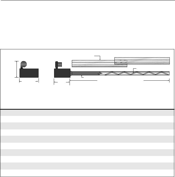
General Specifications for BH-Series heaters are as follows:
End View |
Side View |
Reflector |
|
|
||
|
|
|
|
|
|
|
12.5” |
|
|
|
|
Turbulator (select models) |
|
(32 cm) |
|
|
|
|
||
|
|
|
|
|
|
|
|
12.5” |
|
|
Burner Tube |
|
|
|
|
11” |
Maximum or Minimum Length A |
|
||
|
(32 cm) |
|
|
|
|
|
|
|
(28 cm) |
|
|
|
|
|
|
|
|
|
|
|
|
Heat Input |
|
Length “A” |
Recommended |
||
|
Rate |
|
Minimum Mounting Height* |
|||
|
|
|
|
|||
Model |
(BTUH X1000) |
Minimum |
Maximum |
Space |
Spot |
|
BH-40 |
40 |
|
10’ (3m) |
10’ (3m) |
8'-10' (2.4 - 3m) |
8' (2.4m) |
BH-60 |
60 |
|
20' (6m) |
20' (6m) |
10'-12' (3 - 3.6m) |
9' (2.7m)' |
BH-80 |
80 |
|
20' (6m) |
30' (9m) |
12'-15' (3.6 - 4.5m) |
11' (3.3m) |
BH-100 |
100 |
|
30' (9m) |
40' (12m) |
12'-15' (3.6 - 4.5m) |
12' (3.7m) |
BH-115 |
115 |
|
30' (9m) |
50' (15m) |
15'-20’ (4.5 - 6m) |
15' (4.6m) |
BH-125 |
125 |
|
40' (12m) |
50' (15m) |
15'-20’ (4.5 - 6m) |
15' (4.6m) |
BH-140 |
140 |
|
40' (12m) |
60' (18m) |
20'-25’ (6 - 7.6m) |
20' (6.1m) |
BH-150 |
150 |
|
50' (15m) |
60' (18m) |
20'-25’ (6 - 7.6m) |
20' (6.1m) |
BH-175 |
175 |
|
50' (15m) |
70' (21m) |
25' (7.6m) |
23' (7m) |
BH-200 |
200 |
|
60' (18m) |
80' (24m) |
25' (7.6m) |
25' (7.6m) |
Gas Pressure at Manifold: |
|
|
Natural Gas: |
3 |
.5" w.c. |
LP Gas: |
10 |
.5" w.c. |
Pipe Connection:
1/2" NPT (for BH-40, 60, 80, 100, 115 & 125) 3/4" NPT (for BH140, 150,175 & 200)
Dimensions:
Vent Connection Size: 4" (10 cm) Outside Air Connection Size: 4" (10 cm)
Refer to figure above for dimensional information.
Gas Inlet Pressure: |
|
|
Natural Gas: |
|
|
for BH-40, 60, 80, 100, |
|
|
115, 125, 140, 150 |
4.6" w.c. |
Minimum |
for BH-175, 200 |
5.0" w.c. |
Minimum |
|
14.0" w.c. |
Maximum |
LP Gas: |
11.0" w.c. |
Minimum |
|
14.0" w.c. Maximum |
|
Electrical Rating (all models): |
|
|
120V - 60 Hz., 1.0 Amp
© 2004 Roberts-Gordon |
BEFORE IN STALLATI ON AND OPER ATI ON OF HEATI NG EQUIPMENT, READ AND U NDERSTAND THE INSTALLATION, OPERATIO N AND SERVICE MANUAL. |
APPLICATION S, ENGI NEERING AND DETAI LED GUID ANCE ON SYSTEMS DESIGN, INSTALLATI ON AND PRODUCT PERFORMANCE IS AVAI LABLE UPON REQUEST. ROBERTS GORDON® PRODUCTS ARE TO BE |
|
|
INSTALLED ONLY IN ACCORDANCE WI TH LOCALLAWS, CODES AND REGULATIONS, AND ONLY BY A CONTRACTOR QUALI FIED I N THE I NSTALLATION AND SERVICE OF GAS-FIRED HEATING EQUI PMENT. |
ROBERTS GOR DON® BH-SERI E S SUBM IT TAL SHE E T
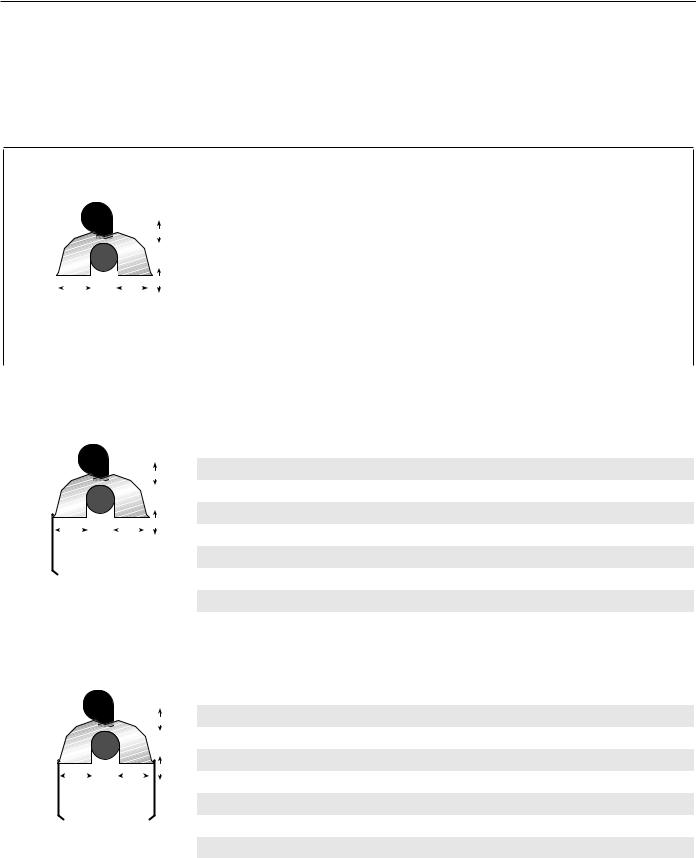
CLEARANCES TO COMBUSTIBLES
NOTE: 1. All dimensions are from the surfaces of all tubes, couplings and elbows.
2. Clearances B, C and D can be reduced by 50% after 25' (7.5 m) of tubing downstream from where the burner and burner tube connect.
3. “-” indicates an unapproved application. Roberts-Gordon prohibits the installation of this heater for all unapproved applications.
Standard Reflector
|
|
|
|
|
|
|
|
|
|
|
|
|
|
|
|
|
|
|
|
|
|
|
|
|
|
|
|
|
|
|
|
(inches) |
|
|
(centimeters) |
|
||
|
|
|
|
|
|
|
|
|
|
|
|
|
|
|
|
|
|
|
|
|
|
|
|
|
|
|
|
|
|
Model |
A |
B |
C |
D |
A |
B |
C |
D |
|
|
|
|
|
|
|
|
|
|
|
|
|
|
|
|
|
|
|
|
|
|
|
|
|
|
|
|
|
|
|||||||||
|
|
|
|
|
|
|
|
|
|
|
|
|
|
|
|
|
|
|
|
|
|
|
|
|
|
|
|
|
|
|
|
|
|
|
|
|
|
|
|
|
|
|
|
|
|
|
|
|
|
|
|
|
|
|
|
|
|
|
|
|
|
|
A |
|
|
BH-40 |
6 |
27 |
52 |
27 |
16 |
69 |
133 |
69 |
|||
|
|
|
|
|
|
|
|
|
|
|
|
|
|
|
|
|
|
|
|
|
|
|
|
|
|
BH-60 |
6 |
35 |
62 |
35 |
16 |
89 |
158 |
89 |
||||
|
|
|
|
|
|
|
|
|
|
|
|
|
|
|
|
|
|
|
|
|
|
|
|
|
|
|
|
|
|
|||||||||
|
|
|
|
|
|
|
|
|
|
|
|
|
|
|
|
|
|
|
|
|
|
|
|
|
|
|
|
|
|
|||||||||
|
|
|
|
|
|
|
|
|
|
|
|
|
|
|
|
|
|
|
|
|
|
|
|
|
|
|
|
|
|
|
|
|
|
|
|
|
|
|
|
|
|
|
|
|
|
|
|
|
|
|
|
|
|
|
|
|
|
|
|
|
|
|
|
|
|
|
|
|
BH-80 |
6 |
38 |
65 |
38 |
16 |
97 |
166 |
97 |
|
|
|
|
|
|
|
|
|
|
|
|
|
|
|
|
|
|
|
|
|
|
|
|
C |
|
|
||||||||||||
|
|
|
|
|
|
B |
|
|
|
|
|
|
|
|
D |
|
|
|
|
|
|
|
BH-100 |
6 |
40 |
70 |
40 |
16 |
102 |
178 |
102 |
|||||||
|
|
|
|
|
|
|
|
|
|
|
|
|
|
|
|
|
|
|
|
|
|
|
|
|
||||||||||||||
|
|
|
|
|
|
|
|
|
|
|
|
|
|
|
|
|
|
|
|
|
|
|
|
|
|
|
|
|
|
|
|
|
|
|
|
|
|
|
|
|
|
|
|
|
|
|
|
|
|
|
|
|
|
|
|
|
|
|
|
|
|
|
|
|
|
|
|
|
BH-115/125 |
6 |
46 |
76 |
46 |
16 |
117 |
194 |
117 |
|
|
|
|
|
|
|
|
|
|
|
|
|
|
|
|
|
|
|
|
|
|
|
|
|
|
|
|
|
|
BH-140/150 |
6 |
50 |
79 |
50 |
16 |
127 |
201 |
127 |
|
|
|
|
|
|
|
|
|
|
|
|
|
|
|
|
|
|
|
|
|
|
|
|
|
|
|
|
|
|
|
|
|
|
|
|
|
|
|
|
|
|
|
|
|
|
|
|
|
|
|
|
|
|
|
|
|
|
|
|
|
|
|
|
|
|
|
|
|
BH-175/200 |
8 |
52 |
82 |
52 |
21 |
133 |
209 |
133 |
|
|
|
|
|
|
|
|
|
|
|
|
|
|
|
|
|
|
|
|
|
|
|
|
|
|
|
|
|
|
|
|
|
|
|
||||
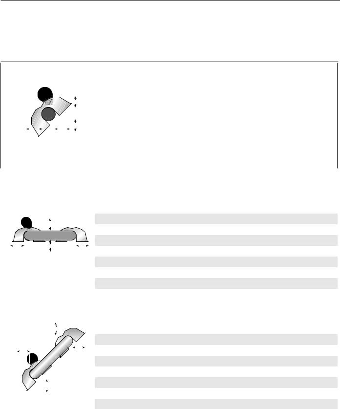
One Side Reflector |
|
|
|
|
|
|
|
|
|
|
|
|
|
|
|
|||||||||||||||||||||||
|
|
|
|
|
|
|
|
|
|
|
|
|
|
|
|
|
|
|
|
|
|
|
|
|
|
|
|
|
|
|
|
|
|
|
|
|
||
|
|
|
|
|
|
|
|
|
|
|
|
|
|
|
|
|
|
|
|
|
|
|
|
|
|
|
|
|
|
|
|
(inches) |
|
|
(centimeters) |
|
||
|
|
|
|
|
|
|
|
|
|
|
|
|
|
|
|
|
|
|
|
|
|
|
|
|
|
|
|
|
|
Model |
A |
B |
C |
D |
A |
B |
C |
D |
|
|
|
|
|
|
|
|
|
|
|
|
|
|
|
|
|
|
|
|
|
|
|
|
|
|
|
|
|
|
|||||||||
|
|
|
|
|
|
|
|
|
|
|
|
|
|
|
|
|
|
|
|
|
|
|
|
A |
|
|
|
|
BH-40 |
6 |
9 |
52 |
44 |
16 |
23 |
133 |
112 |
|
|
|
|
|
|
|
|
|
|
|
|
|
|
|
|
|
|
|
|
|
|
|
|
|
|
|
|
|
|
|
BH-60 |
6 |
9 |
62 |
47 |
16 |
23 |
158 |
120 |
|
|
|
|
|
|
|
|
|
|
|
|
|
|
|
|
|
|
|
|
|
|
|
|
|
|
|
|
|
|
|||||||||
|
|
|
|
|
|
|
|
|
|
|
|
|
|
|
|
|
|
|
|
|
|
|
|
|
|
|
|
|
|
BH-80 |
6 |
9 |
69 |
54 |
16 |
23 |
176 |
138 |
|
|
|
|
|
|
|
|
|
|
|
|
|
|
|
|
|
|
|
|
|
|
|
|
C |
|
|
|
|
||||||||||
|
|
|
|
B |
|
|
|
|
|
|
|
|
|
D |
|
|
|
|
|
|
|
|
|
|
BH-100 |
6 |
9 |
76 |
59 |
16 |
23 |
194 |
150 |
|||||
|
|
|
|
|
|
|
|
|
|
|
|
|
|
|
|
|
|
|
|
|
|
|||||||||||||||||
|
|
|
|
|
|
|
|
|
|
|
|
|
|
|
|
|
|
|
|
|
|
|
|
|
|
|
|
|
|
|||||||||
|
|
|
|
|
|
|
|
|
|
|
|
|
|
|
|
|
|
|
|
|
|
|
|
|
|
|
|
|
|
|||||||||
|
|
|
|
|
|
|
|
|
|
|
|
|
|
|
|
|
|
|
|
|
|
|
|
|
|
|
|
|
|
BH-115/125 |
6 |
9 |
82 |
65 |
16 |
23 |
209 |
166 |
|
|
|
|
|
|
|
|
|
|
|
|
|
|
|
|
|
|
|
|
|
|
|
|
|
|
|
|
|
|
BH-140/150 |
6 |
9 |
85 |
69 |
16 |
23 |
216 |
176 |
|
|
|
|
|
|
|
|
|
|
|
|
|
|
|
|
|
|
|
|
|
|
|
|
|
|
|
|
|
|
|||||||||
|
|
|
|
|
|
|
|
|
|
|
|
|
|
|
|
|
|
|
|
|
|
|
|
|
|
|
|
|
|
BH-175/200 |
8 |
9 |
88 |
73 |
21 |
23 |
224 |
186 |
|
|
|
|
|
|
|
|
|
|
|
|
|
|
|
|
|
|
|
|
|
|
|
|
|
|
|
|
|||||||||||
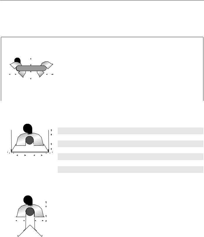
Two Side Reflectors |
|
|
|
|
|
|
|
|
|
|
|
|
|
|
|
|||||||||||||||||||||||
|
|
|
|
|
|
|
|
|
|
|
|
|
|
|
|
|
|
|
|
|
|
|
|
|
|
|
|
|
|
|
|
|
|
|
|
|
||
|
|
|
|
|
|
|
|
|
|
|
|
|
|
|
|
|
|
|
|
|
|
|
|
|
|
|
|
|
|
|
|
(inches) |
|
|
(centimeters) |
|
||
|
|
|
|
|
|
|
|
|
|
|
|
|
|
|
|
|
|
|
|
|
|
|
|
|
|
|
|
|
|
Model |
A |
B |
C |
D |
A |
B |
C |
D |
|
|
|
|
|
|
|
|
|
|
|
|
|
|
|
|
|
|
|
|
|
|
|
|
|
|
|
|
|
|
|||||||||
|
|
|
|
|
|
|
|
|
|
|
|
|
|
|
|
|
|
|
|
|
|
|
|
A |
|
BH-40 |
6 |
15 |
52 |
15 |
16 |
39 |
133 |
39 |
||||
|
|
|
|
|
|
|
|
|
|
|
|
|
|
|
|
|
|
|
|
|
|
|
|
|
|
|
|
|
|
BH-60 |
6 |
23 |
65 |
23 |
16 |
59 |
166 |
59 |
|
|
|
|
|
|
|
|
|
|
|
|
|
|
|
|
|
|
|
|
|
|
|
|
|
|
|
|
|
|
|||||||||
|
|
|
|
|
|
|
|
|
|
|
|
|
|
|
|
|
|
|
|
|
|
|
|
|
|
|
|
|
|
BH-80 |
6 |
25 |
71 |
25 |
16 |
64 |
181 |
64 |
|
|
|
|
|
|
|
|
|
|
|
|
|
|
|
|
|
|
|
|
|
|
|
|
C |
|
|||||||||||||
|
|
|
|
|
|
B |
|
|
|
|
|
|
|
|
D |
|
|
|
|
|
BH-100 |
6 |
27 |
77 |
27 |
16 |
69 |
196 |
69 |
|||||||||
|
|
|
|
|
|
|
|
|
|
|
|
|
|
|
|
|
|
|
|
|
||||||||||||||||||
|
|
|
|
|
|
|
|
|
|
|
|
|
|
|
|
|
|
|
|
|
|
|
|
|
|
|
|
|
|
|||||||||
|
|
|
|
|
|
|
|
|
|
|
|
|
|
|
|
|
|
|
|
|
|
|
|
|
|
|
|
|
|
|||||||||
|
|
|
|
|
|
|
|
|
|
|
|
|
|
|
|
|
|
|
|
|
|
|
|
|
|
|
|
|
|
BH-115/125 |
6 |
32 |
83 |
32 |
16 |
82 |
211 |
82 |
|
|
|
|
|
|
|
|
|
|
|
|
|
|
|
|
|
|
|
|
|
|
|
|
|
|
|
|
|
|
BH-140/150 |
6 |
35 |
87 |
35 |
16 |
89 |
221 |
89 |
|
|
|
|
|
|
|
|
|
|
|
|
|
|
|
|
|
|
|
|
|
|
|
|
|
|
|
|
|
|
|||||||||
|
|
|
|
|
|
|
|
|
|
|
|
|
|
|
|
|
|
|
|
|
|
|
|
|
|
|
|
|
|
BH-175/200 |
8 |
40 |
91 |
40 |
21 |
102 |
232 |
102 |
|
|
|
|
|
|
|
|
|
|
|
|
|
|
|
|
|
|
|
|
|
|
|
|
|
|
|
|
|
|
|
|
|
|
|
|
|
|
|
© 2004 Roberts-Gordon BEFORE IN STALLATI ON AND OPER ATI ON OF HEATI NG EQUIPMENT, READ AND U NDERSTAND THE INSTALLATION, OPERATIO N AND SERVICE MANUAL.
APPLICATION S, ENGI NEERING AND DETAI LED GUID ANCE ON SYSTEMS DESIGN, INSTALLATI ON AND PRODUCT PERFORMANCE IS AVAI LABLE UPON REQUEST. ROBERTS GORDON® PRODUCTS ARE TO BE INSTALLED ONLY IN ACCORDANCE WI TH LOCALLAWS, CODES AND REGULATIONS, AND ONLY BY A CONTRACTOR QUALI FIED I N THE I NSTALLATION AND SERVICE OF GAS-FIRED HEATING EQUI PMENT.
ROBERTS GORDON ® BH-SERI E S SUBM IT TAL SHE E T
NOTE: 1. All dimensions are from the surfaces of all tubes, couplings and elbows.
2.Clearances B, C and D can be reduced by 50% after 25' (7.5 m) of tubing downstream from where the burner and burner tube connect.
3.“-” indicates an unapproved application. Roberts-Gordon prohibits the installation of this heater for all unapproved applications.
45° Tilt Reflector
|
|
|
|
|
|
|
|
|
|
|
|
|
|
|
|
|
|
|
|
|
|
|
|
|
|
|
|
|
|
|
|
|
|
|
|
|
|
|
|
|
(inches) |
|
|
(centimeters) |
|
||
|
|
|
|
|
|
|
|
|
|
|
|
|
|
|
|
|
|
|
|
|
|
|
|
|
|
|
|
|
|
|
|
|
|
|
|
|
|
|
Model |
A |
B |
C |
D |
A |
B |
C |
D |
|
|
|
|
|
|
|
|
|
|
|
|
|
|
|
|
|
|
|
|
|
|
|
|
|
|
|
|
|
|
|
|
|
|
|
|
|
|
|
|||||||||
|
|
|
|
|
|
|
|
|
|
|
|
|
|
|
|
|
|
|
|
|
|
|
|
|
|
|
|
|
|
|
|
|
|
|
|
|
|
|
|
|
|
|
|
|
|
|
|
|
|
|
|
|
|
|
|
|
|
|
|
|
|
|
|
|
|
|
|
|
|
|
|
|
|
|
|
A |
|
|
|
|
|
|
BH-40 |
8 |
8 |
50 |
46 |
21 |
21 |
127 |
117 |
||||
|
|
|
|
|
|
|
|
|
|
|
|
|
|
|
|
|
|
|
|
|
|
|
|
|
|
|
|
|
|
|
|
|
|
BH-60 |
8 |
8 |
59 |
54 |
21 |
21 |
150 |
138 |
|||||
|
|
|
|
|
|
|
|
|
|
|
|
|
|
|
|
|
|
|
|
|
|
|
|
|
|
|
|
|
|
|
|
|
|
|
|
|
|
|
|||||||||
|
|
|
|
|
|
|
|
|
|
|
|
|
|
|
|
|
|
|
|
|
|
|
|
|
|
|
|
|
|
|
|
|
|
|
|
|
|
|
|||||||||
|
|
|
|
|
|
|
|
|
|
|
|
|
|
|
|
|
|
|
|
|
|
|
|
|
|
|
|
|
|
|
|
|
|
|
|
|
|
|
|
|
|
|
|
|
|
|
|
|
|
|
|
|
|
|
|
|
|
|
|
|
|
|
|
|
|
|
|
|
|
|
|
|
|
|
|
|
|
|
|
|
|
|
|
|
|
|
BH-80 |
8 |
8 |
65 |
60 |
21 |
21 |
166 |
153 |
|
|
|
|
|
|
|
|
|
|
|
|
|
|
|
|
|
|
|
|
|
|
|
|
|
|
|
|
C |
|
|
|
|
|
|
|||||||||||||
|
|
|
|
|
|
|
|
|
|
|
|
|
|
B |
|
|
|
|
|
|
|
|
|
D |
|
|
|
|
|
|
|
|
|
BH-100 |
10 |
8 |
73 |
64 |
26 |
21 |
186 |
163 |
|||||
|
|
|
|
|
|
|
|
|
|
|
|
|
|
|
|
|
|
|
|
|
|
|
|
|
|
|
|
|
|
|
|
|
|
|
|
|
|||||||||||
|
|
|
|
|
|
|
|
|
|
|
|
|
|
|
|
|
|
|
|
|
|
|
|
|
|
|
|
|
|
|
|
|
|
|
|
|
|
|
|
|
|
|
|
|
|
|
|
|
|
|
|
|
|
|
|
|
|
|
|
|
|
|
|
|
|
|
|
|
|
|
|
|
|
|
|
|
|
|
|
|
|
|
|
|
|
|
BH-115/125 |
10 |
8 |
77 |
69 |
26 |
21 |
196 |
176 |
|
|
|
|
|
|
|
|
|
|
|
|
|
|
|
|
|
|
|
|
|
|
|
|
|
|
|
|
|
|
|
|
|
|
|
|
|
|
|
BH-140/150 |
12 |
8 |
83 |
74 |
31 |
21 |
211 |
188 |
|
|
|
|
|
|
|
|
|
|
|
|
|
|
|
|
|
|
|
|
|
|
|
|
|
|
|
|
|
|
|
|
|
|
|
|
|
|
|
|
|
|
|
|
|
|
|
|
|
|
|
|
|
|
|
|
|
|
|
|
|
|
|
|
|
|
|
|
|
|
|
|
|
|
|
|
|
|
|
|
|
|
|
|
|
|
|
BH-175/200 |
12 |
8 |
85 |
79 |
31 |
21 |
216 |
201 |
|
|
|
|
|
|
|
|
|
|
|
|
|
|
|
|
|
|
|
|
|
|
|
|
|
|
|
|
|
|
|
|
|
|
|
|
|
|
|
|
||||||||
U-Tube, Standard Reflector |
|
|
|
|
|
|
|
|
|
||||||||||||||||||||||||||||||||||||||
|
|
|
|
|
|
|
|
|
|
|
|
|
|
|
|
|
|
|
|
|
|
|
|
|
|
|
|
|
|
|
|
|
|
|
|
|
|
|
|
|
|
|
|
|
|
||
|
|
|
|
|
|
|
|
|
|
|
|
|
|
|
|
|
|
|
|
|
|
|
|
|
|
|
|
|
|
|
|
|
|
|
|
|
|
|
|
|
(inches) |
|
|
(centimeters) |
|
||
|
|
|
|
|
|
|
|
|
|
|
|
|
|
|
|
|
|
|
|
|
|
|
|
|
|
|
|
|
|
|
|
|
|
|
|
|
|
|
Model |
A |
B |
C |
D |
A |
B |
C |
D |
|
|
|
|
|
|
|
|
|
|
|
|
|
|
|
|
|
|
|
|
|
|
|
|
|
|
|
|
|
|
|
|
|
|
|
|
|
|
|
BH-40 |
- |
- |
- |
- |
- |
- |
- |
- |
|
|
|
|
|
|
|
|
|
|
|
|
|
|
|
|
|
|
|
|
|
|
|
|
|
|
|
|
|
|
|
|
|
|
|
|
|
|
|
|||||||||
|
|
|
|
|
|
|
|
|
|
|
|
|
|
|
|
|
|
|
|
|
|
|
|
|
|
|
|
|
|
|
|
|
|
|
|
|
|
|
|||||||||
|
|
|
|
|
|
|
|
|
|
|
|
|
|
|
|
|
|
A |
|
|
|
|
|
|
|
|
|
|
|
|
|
|
BH-60 |
6 |
35 |
62 |
30 |
16 |
89 |
158 |
77 |
||||||
|
|
|
|
|
|
|
|
|
|
|
|
|
|
|
|
|
|
|
|
|
|
|
|
|
|
|
|
|
|
|
|
|
|
|
|
|
|
|
|||||||||
|
|
|
|
|
|
|
|
|
|
|
|
|
|
|
|
|
|
|
|
|
|
|
|
|
|
|
|
|
|
|
|
|
|
|
|
|
|
|
|||||||||
|
|
|
|
|
|
|
|
|
|
|
|
|
|
|
|
|
|
|
|
|
|
|
|
|
|
|
|
|
|
|
|
|
|
|
|
|
|
|
BH-80 |
6 |
38 |
68 |
37 |
16 |
97 |
173 |
94 |
|
|
|
|
|
|
|
|
|
|
|
|
|
|
|
|
|
|
C |
|
|
|
|
|
|
|
|
|
|
|
|
|
|
|||||||||||||||
|
|
|
|
|
B |
|
|
|
|
|
|
|
|
|
|
|
|
|
|
|
|
|
|
|
|
D |
|
||||||||||||||||||||
|
|
|
|
|
|
|
|
|
|
|
|
|
|
|
|
|
|
|
|
|
|
|
|
|
BH-100 |
6 |
40 |
75 |
39 |
16 |
102 |
191 |
100 |
||||||||||||||
|
|
|
|
|
|
|
|
|
|
|
|
|
|
|
|
|
|
|
|||||||||||||||||||||||||||||
|
|
|
|
|
|
|
|
|
|
|
|
|
|
|
|
|
|
|
|
|
|
|
|
|
|
|
|
|
|
|
|
|
|
|
|
|
|
|
|||||||||
|
|
|
|
|
|
|
|
|
|
|
|
|
|
|
|
|
|
|
|
|
|
|
|
|
|
|
|
|
|
|
|
|
|
|
|
|
|
|
|||||||||
|
|
|
|
|
|
|
|
|
|
|
|
|
|
|
|
|
|
|
|
|
|
|
|
|
|
|
|
|
|
|
|
|
|
|
|
|
|
|
BH-115/125 |
6 |
46 |
78 |
43 |
16 |
117 |
199 |
110 |
|
|
|
|
|
|
|
|
|
|
|
|
|
|
|
|
|
|
|
|
|
|
|
|
|
|
|
|
|
|
|
|
|
|
|
|
|
|
|
BH-140/150 |
6 |
50 |
83 |
47 |
16 |
127 |
211 |
120 |
|
|
|
|
|
|
|
|
|
|
|
|
|
|
|
|
|
|
|
|
|
|
|
|
|
|
|
|
|
|
|
|
|
|
|
|
|
|
|
BH-175/200 |
8 |
54 |
87 |
51 |
21 |
138 |
221 |
130 |
|
|
|
|
|
|
|
|
|
|
|
|
|
|
|
|
|
|
|
|
|
|
|
|
|
|
|
|
|
|
|
|
|
|
|
|
||||||||||||
U-Tube, Full 45° |
|
|
|
|
|
|
|
|
|
|
|
|
|
|
|
|
|
|
|
|
|
|
|
||||||||||||||||||||||||
|
|
|
|
|
|
|
|
|
|
|
|
|
|
|
|
|
|
|
|
|
|
|
|
|
|
|
|
|
|
|
|
|
|
|
|
|
|
|
|
|
|
|
|
|
|
||
|
|
|
|
|
|
|
|
|
|
|
|
|
|
|
|
|
|
|
|
|
|
|
|
|
|
|
|
|
|
|
|
|
|
|
|
|
|
|
|
|
(inches) |
|
|
(centimeters) |
|
||
|
|
|
|
|
|
|
|
|
|
|
|
|
|
|
|
|
|
|
|
|
A |
|
|
|
|
|
|
|
|
|
|
|
|
|
|
Model |
A |
B |
C |
D |
A |
B |
C |
D |
|||
|
|
|
|
|
|
|
|
|
|
|
|
|
|
|
|
|
|
|
|
|
|
|
|
|
|
|
|
|
|
|
D |
|
|
|
|
BH-40 |
- |
- |
- |
- |
- |
- |
- |
- |
|||
|
|
|
|
|
|
|
|
|
|
|
|
|
|
|
|
|
|
|
|
|
|
|
|
|
|
|
|
|
|
|
|
|
|
|
|||||||||||||
|
|
|
|
|
|
|
|
|
|
|
|
|
|
|
|
|
|
|
|
|
|
|
|
|
|
|
|
|
|
|
|
|
|
|
|||||||||||||
|
|
|
|
|
|
|
|
B |
|
|
|
|
|
|
|
|
|
|
|
|
|
|
|
|
|
|
|
|
|
|
|
|
BH-60 |
8 |
8 |
59 |
42 |
21 |
21 |
150 |
107 |
||||||
|
|
|
|
|
|
|
|
|
|
|
|
|
|
|
|
|
|
|
|
|
|
|
|
|
|
|
|
|
|
|
|
|
|||||||||||||||
|
|
|
|
|
|
|
|
|
|
|
|
|
|
|
|
|
|
|
|
|
|
|
|
|
|
|
|
|
|
|
|
|
|
|
|
||||||||||||
|
|
|
|
|
|
|
|
|
|
|
|
|
|
|
|
|
|
|
|
|
|
|
|
|
|
|
|
|
|
|
|
|
|
|
|
|
|
|
BH-80 |
8 |
8 |
65 |
46 |
21 |
21 |
166 |
117 |
|
|
|
|
|
|
|
|
|
|
|
|
|
|
|
|
|
|
|
|
|
|
|
|
|
|
|
|
|
|
|
|
|
|
|
|
|
|
|
BH-100 |
8 |
8 |
73 |
52 |
21 |
21 |
186 |
133 |
|
|
|
|
|
|
|
|
|
|
|
|
|
|
|
|
|
|
|
|
|
|
|
|
|
|
|
|
|
|
|
|
|
|
|
|
|
|
|
|||||||||
|
|
|
|
|
|
|
|
|
|
|
|
|
|
|
|
|
|
|
|
|
|
|
|
|
|
|
|
|
|
|
|
|
|
|
|
|
|
|
BH-115/125 |
8 |
8 |
77 |
61 |
21 |
21 |
196 |
155 |
|
|
|
|
|
|
|
|
|
|
|
|
|
|
|
|
|
|
|
|
|
|
|
|
|
|
|
|
|
|
|
|
|
|
|
|
|
|
|
|||||||||
|
|
|
|
|
|
|
|
|
|
|
|
|
|
|
|
|
|
|
|
|
|
|
|
|
|
|
|
|
|
|
|
|
|
|
|
|
|
|
|||||||||
|
|
|
|
|
|
|
|
|
|
|
|
|
|
|
|
|
|
|
|
|
|
|
|
|
|
|
|
|
|
|
|
|
|
|
|
|
|
|
BH-140/150 |
8 |
8 |
83 |
66 |
21 |
21 |
211 |
168 |
|
|
|
|
|
|
|
|
|
|
|
|
|
|
|
|
|
|
|
|
|
|
|
|
|
|
|
|
|
|
|
|
|
|
|
|
|
|
|
|||||||||
|
|
|
|
|
|
|
|
|
|
|
|
|
|
|
|
|
|
|
|
|
|
|
|
|
|
|
|
|
|
|
|
|
|
|
|
|
|
|
|||||||||
|
|
|
|
|
|
|
|
|
|
|
|
|
|
|
|
|
|
|
|
|
|
|
|
|
|
|
|
|
|
|
|
|
|
|
|
|
|
|
|||||||||
|
|
|
|
|
|
|
|
|
|
|
|
|
|
|
|
|
|
|
|
|
|
|
|
|
|
|
|
|
|
|
|
|
|
|
|
|
|
|
BH-175/200 |
8 |
8 |
85 |
70 |
21 |
21 |
216 |
178 |
© 2004 Roberts-Gordon |
BEFORE IN STALLATI ON AND OPER ATI ON OF HEATI NG EQUIPMENT, READ AND U NDERSTAND THE INSTALLATION, OPERATIO N AND SERVICE MANUAL. |
APPLICATION S, ENGI NEERING AND DETAI LED GUID ANCE ON SYSTEMS DESIGN, INSTALLATI ON AND PRODUCT PERFORMANCE IS AVAI LABLE UPON REQUEST. ROBERTS GORDON® PRODUCTS ARE TO BE |
|
|
INSTALLED ONLY IN ACCORDANCE WI TH LOCALLAWS, CODES AND REGULATIONS, AND ONLY BY A CONTRACTOR QUALI FIED I N THE I NSTALLATION AND SERVICE OF GAS-FIRED HEATING EQUI PMENT. |
ROBERTS GOR DON® BH-SERI E S SUBM IT TAL SHE E T
NOTE: 1. All dimensions are from the surfaces of all tubes, couplings and elbows.
2.Clearances B, C and D can be reduced by 50% after 25' (7.5 m) of tubing downstream from where the burner and burner tube connect.
3.“-” indicates an unapproved application. Roberts-Gordon prohibits the installation of this heater for all unapproved applications.
U-Tube, Opposite 45° Reflector
|
|
|
|
|
|
|
|
|
|
|
|
|
|
|
|
|
|
|
|
|
|
|
|
|
|
|
|
|
|
|
|
|
|
|
|
|
(inches) |
|
|
(centimeters) |
|
||
|
|
|
|
|
|
|
|
|
|
|
|
|
|
|
|
|
|
|
|
|
|
|
|
|
|
|
|
|
|
|
|
|
|
|
Model |
A |
B |
C |
D |
A |
B |
C |
D |
|
|
|
|
|
|
|
|
|
|
|
|
|
|
|
|
|
|
|
|
|
|
|
|
|
|
|
|
|
|
|
|
|
|
|
|
|
|
|
|
|
|
|
|
|
|
|
|
|
|
|
|
|
|
|
|
|
|
|
|
|
|
|
|
|
|
|
|
|
|
|
|
|
|
|
|
|
|
|
BH-40 |
- |
- |
- |
- |
- |
- |
- |
- |
|
|
|
|
|
|
|
|
|
|
|
|
|
|
|
|
|
|
|
|
|
|
|
|
|
|
|
|
|
|
|
|
|
|
|
|||||||||
|
|
|
|
|
|
|
|
|
|
|
|
|
|
|
|
|
|
|
|
|
|
|
|
|
|
|
|
|
|
|
|
|
|
|
|||||||||
|
|
|
|
|
|
|
|
|
|
|
|
|
|
A |
|
|
|
|
|
|
|
|
|
|
|
|
|
|
|
|
|
|
|
|
|
||||||||
|
|
|
|
|
|
|
|
|
|
|
|
|
|
|
|
|
|
|
|
|
|
|
BH-60 |
8 |
54 |
59 |
22 |
21 |
138 |
150 |
56 |
||||||||||||
|
|
|
|
|
|
|
|
|
|
|
|
|
|
|
|
|
|
|
|
|
|
|
|
|
|
|
|
|
|
|
|
|
|
|
|||||||||
|
|
|
|
|
|
|
|
|
|
|
|
|
|
|
|
|
|
|
|
|
|
|
|
|
|
|
|
|
|
|
|
|
|
|
|||||||||
|
|
|
|
|
|
|
|
|
|
|
|
|
|
|
|
|
|
|
|
|
|
|
|
|
|
|
|
|
|
|
|
|
|
|
|
|
|
|
|
|
|
|
|
|
|
|
|
|
|
|
|
|
|
|
|
|
|
|
|
|
|
|
|
|
|
|
|
|
|
|
|
|
D |
|
BH-80 |
8 |
60 |
65 |
22 |
21 |
153 |
166 |
56 |
||||
|
|
|
|
|
|
|
|
|
|
|
|
|
|
|
|
|
|
|
|
|
|
|
|
|
|
|
|
|
|
||||||||||||||
|
|
|
B |
|
|
|
|
|
|
|
|
|
|
C |
|
|
|
|
|
|
|
BH-100 |
10 |
64 |
73 |
22 |
26 |
163 |
186 |
56 |
|||||||||||||
|
|
|
|
|
|
|
|
|
|
|
|
|
|
|
|
|
|
|
|
|
|
||||||||||||||||||||||
|
|
|
|
|
|
|
|
|
|
|
|
|
|
|
|
|
|
|
|
|
|
|
|
|
|
|
|
|
|
|
|
|
|
|
|||||||||
|
|
|
|
|
|
|
|
|
|
|
|
|
|
|
|
|
|
|
|
|
|
|
|
|
|
|
|
|
|
|
|
|
|
|
|||||||||
|
|
|
|
|
|
|
|
|
|
|
|
|
|
|
|
|
|
|
|
|
|
|
|
|
|
|
|
|
|
|
|
|
|
|
|
|
|
|
|
|
|
|
|
|
|
|
|
|
|
|
|
|
|
|
|
|
|
|
|
|
|
|
|
|
|
|
|
|
|
|
|
|
|
|
|
|
|
|
BH-115/125 |
10 |
70 |
77 |
22 |
26 |
178 |
196 |
56 |
|
|
|
|
|
|
|
|
|
|
|
|
|
|
|
|
|
|
|
|
|
|
|
|
|
|
|
|
|
|
|
|
|
|
|
BH-140/150 |
12 |
74 |
83 |
22 |
31 |
188 |
211 |
56 |
|
|
|
|
|
|
|
|
|
|
|
|
|
|
|
|
|
|
|
|
|
|
|
|
|
|
|
|
|
|
|
|
|
|
|
|
|
|
|
|
|
|
|
|
|
|
|
|
|
|
|
|
|
|
|
|
|
|
|
|
|
|
|
|
|
|
|
|
|
|
|
|
|
|
|
|
|
|
|
BH-175/200 |
12 |
76 |
85 |
22 |
31 |
194 |
216 |
56 |
|
|
|
|
|
|
|
|
|
|
|
|
|
|
|
|
|
|
|
|
|
|
|
|
|
|
|
|
|
|
|
|
||||||||||||
2-Foot Deco Grille, 1-Foot Deco Grille and Protective Grille |
|
|
|
|
|
||||||||||||||||||||||||||||||||||||||
|
|
|
|
|
|
|
|
|
|
|
|
|
|
|
|
|
|
|
|
|
|
|
|
|
|
|
|
|
|
|
|
|
|
|
|
|
|
|
|
|
|
||
|
|
|
|
|
|
|
|
|
|
|
|
|
|
|
|
|
|
|
|
|
|
|
|
|
|
|
|
|
|
|
|
|
|
|
|
|
(inches) |
|
|
(centimeters) |
|
||
|
|
|
|
|
|
|
|
|
|
|
|
|
|
|
|
|
|
|
|
|
|
|
|
|
|
|
|
|
|
|
|
|
|
|
Model |
A |
B |
C |
D |
A |
B |
C |
D |
|
|
|
|
|
|
|
|
|
|
|
|
|
|
|
|
|
|
|
|
|
|
|
|
|
|
|
|
|
|
|
|
|
|
|
|||||||||
|
|
|
|
|
|
|
|
|
|
|
|
|
|
|
|
|
|
|
|
|
|
|
|
|
|
|
|
|
|
A |
|
|
BH-40 |
6 |
27 |
52 |
27 |
16 |
69 |
133 |
69 |
||
|
|
|
|
|
|
|
|
|
|
|
|
|
|
|
|
|
|
|
|
|
|
|
|
|
|
|
|
|
|
|
|
|
|
|
|
|
|
|
|
||||
|
|
|
|
|
|
|
|
|
|
|
|
|
|
|
|
|
|
|
|
|
|
|
|
|
|
|
|
|
|
|
|
|
|
|
BH-60 |
6 |
35 |
62 |
35 |
16 |
89 |
158 |
89 |
|
|
|
|
|
|
|
|
|
|
|
|
|
|
|
|
|
|
|
|
|
|
|
|
|
|
|
|
|
|
|
|
|
|
|
|||||||||
|
|
|
|
|
|
|
|
|
|
|
|
|
|
|
|
|
|
|
|
|
|
|
|
|
|
|
|
|
|
|
|
|
|
|
BH-80 |
6 |
38 |
65 |
38 |
16 |
97 |
166 |
97 |
|
|
|
|
|
|
|
|
|
|
|
|
|
|
|
|
|
|
|
|
|
|
|
|
|
|
|
|
|
|
C |
|
|
|||||||||||
|
|
|
|
|
|
|
|
|
B |
|
|
|
|
|
|
|
|
D |
|
|
|
|
|
|
|
|
|
|
|
BH-100 |
6 |
40 |
70 |
40 |
16 |
102 |
178 |
102 |
|||||
|
|
|
|
|
|
|
|
|
|
|
|
|
|
|
|
|
|
|
|
|
|
|
|
|
|
|
|
|
|
|
|||||||||||||
|
|
|
|
|
|
|
|
|
|
|
|
|
|
|
|
|
|
|
|
|
|
|
|
|
|
|
|
|
|
|
BH-115/125 |
6 |
46 |
76 |
46 |
16 |
117 |
194 |
117 |
||||
|
|
|
|
|
|
|
|
|
|
|
|
|
|
|
|
|
|
|
|
|
|
|
|
|
|
|
|
|
|
||||||||||||||
|
|
|
|
|
|
|
|
|
|
|
|
|
|
|
|
|
|
|
|
|
|
|
|
|
|
|
|
|
|
|
|
|
|
|
|||||||||
|
|
|
|
|
|
|
|
|
|
|
|
|
|
|
|
|
|
|
|
|
|
|
|
|
|
|
|
|
|
|
|
|
|
|
BH-140/150 |
6 |
50 |
79 |
50 |
16 |
127 |
201 |
127 |
|
|
|
|
|
|
|
|
|
|
|
|
|
|
|
|
|
|
|
|
|
|
|
|
|
|
|
|
|
|
|
|
|
|
|
|||||||||
|
|
|
|
|
|
|
|
|
|
|
|
|
|
|
|
|
|
|
|
|
|
|
|
|
|
|
|
|
|
|
|
|
|
|
BH-175/200 |
8 |
52 |
82 |
52 |
21 |
133 |
209 |
133 |
|
|
|
|
|
|
|
|
|
|
|
|
|
|
|
|
|
|
|
|
|
|
||||||||||||||||||||||
Lower Clearance Shield* |
|
|
|
|
|
|
|
|
|
||||||||||||||||||||||||||||||||||
|
|
|
|
|
|
|
|
|
|
|
|
|
|
|
|
|
|
|
|
|
|
|
|
|
|
|
|
|
|
|
|
|
|
|
|
|
|
|
|
|
|
||
|
|
|
|
|
|
|
|
|
|
|
|
|
|
|
|
|
|
|
|
|
|
|
|
|
|
|
|
|
|
|
|
|
|
|
|
|
(inches) |
|
|
(centimeters) |
|
||
|
|
|
|
|
|
|
|
|
|
|
|
|
|
|
|
|
|
|
|
|
|
|
|
|
|
|
|
|
|
|
|
|
|
|
Model |
A |
B |
C |
D |
A |
B |
C |
D |
|
|
|
|
|
|
|
|
|
|
|
|
|
|
|
|
|
|
|
|
|
|
|
|
|
|
|
|
|
|
|
|
|
|
|
|||||||||
|
|
|
|
|
|
|
|
|
|
|
|
|
|
|
|
|
|
|
|
|
|
|
|
|
|
|
|
|
|
|
|
|
|
|
|
|
|
|
|
|
|
||
|
|
|
|
|
|
|
|
|
|
|
|
|
|
|
|
|
|
|
|
|
|
|
|
A |
|
|
|
|
|
|
|
BH-40 |
6 |
34 |
27 |
34 |
16 |
87 |
69 |
87 |
|||
|
|
|
|
|
|
|
|
|
|
|
|
|
|
|
|
|
|
|
|
|
|
|
|
|
|
|
|
|
|
|
|
|
|
|
BH-60 |
6 |
39 |
33 |
39 |
16 |
100 |
84 |
100 |
|
|
|
|
|
|
|
|
|
|
|
|
|
|
|
|
|
|
|
|
|
|
|
|
|
|
|
|
|
|
|
|
|
|
|
|||||||||
|
|
|
|
|
|
|
|
|
|
|
|
|
|
|
|
|
|
|
|
|
|
|
|
|
|
|
|
|
|
|
|
|
|
|
|
|
|
|
|
|
|
|
|
|
|
|
|
|
|
|
|
|
|
|
|
|
|
|
|
|
|
|
|
|
|
|
|
|
|
|
|
|
|
|
|
|
|
|
BH-80 |
6 |
40 |
38 |
40 |
16 |
102 |
97 |
102 |
|
|
|
|
|
|
|
|
|
|
|
|
|
|
|
|
|
|
|
|
|
|
|
|
C |
|
|
|
|
|
|
|
||||||||||||
|
|
|
|
|
|
|
|
B |
|
|
|
|
|
|
|
|
|
|
D |
|
|
|
|
|
|
|
|
|
BH-100 |
6 |
50 |
44 |
50 |
16 |
127 |
112 |
127 |
||||||
|
|
|
|
|
|
|
|
|
|
|
|
|
|
|
|
|
|
|
|
|
|
|
|
|
|
|
|
|
|
|
|||||||||||||
|
|
|
|
|
|
|
|
|
|
|
|
|
|
|
|
|
|
|
|
|
|
|
|
|
|
|
|
|
|
|
|
|
|
|
|||||||||
|
|
|
|
|
|
|
|
|
|
|
|
|
|
|
|
|
|
|
|
|
|
|
|
|
|
|
|
|
|
|
|
|
|
|
|
|
|
|
|
|
|
|
|
|
|
|
|
|
|
|
|
|
|
|
|
|
|
|
|
|
|
|
|
|
|
|
|
|
|
|
|
|
|
|
|
|
|
|
BH-115/125 |
6 |
54 |
48 |
54 |
16 |
138 |
122 |
138 |
|
|
|
|
|
|
|
|
|
|
|
|
|
|
|
|
|
|
|
|
|
|
|
|
|
|
|
|
|
|
|
|
|
|
|
BH-140/150 |
6 |
55 |
50 |
55 |
16 |
140 |
127 |
140 |
|
|
|
|
|
|
|
|
|
|
|
|
|
|
|
|
|
|
|
|
|
|
|
|
|
|
|
|
|
|
|
|
|
|
|
|
|
|
|
|
|
|
|
|
|
|
|
|
|
|
|
|
|
|
|
|
|
|
|
|
|
|
|
|
|
|
|
|
|
|
|
|
|
|
|
|
|
|
|
BH-175/200 |
- |
- |
- |
- |
- |
- |
- |
- |
*When installed in the first 20’ (6 m).
© 2004 Roberts-Gordon BEFORE IN STALLATI ON AND OPER ATI ON OF HEATI NG EQUIPMENT, READ AND U NDERSTAND THE INSTALLATION, OPERATIO N AND SERVICE MANUAL.
APPLICATION S, ENGI NEERING AND DETAI LED GUID ANCE ON SYSTEMS DESIGN, INSTALLATI ON AND PRODUCT PERFORMANCE IS AVAI LABLE UPON REQUEST. ROBERTS GORDON® PRODUCTS ARE TO BE INSTALLED ONLY IN ACCORDANCE WI TH LOCALLAWS, CODES AND REGULATIONS, AND ONLY BY A CONTRACTOR QUALI FIED I N THE I NSTALLATION AND SERVICE OF GAS-FIRED HEATING EQUI PMENT.
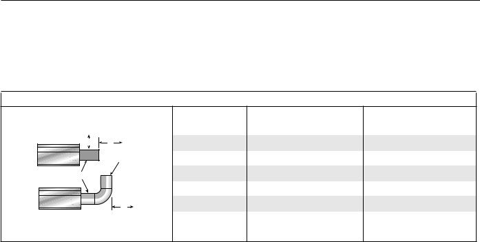
ROBERTS GORDON ® BH-SERI E S SUBM IT TAL SHE E T
NOTE: 1. All dimensions are from the surfaces of all tubes, couplings and elbows.
2.Clearances B, C and D can be reduced by 50% after 25' (7.5 m) of tubing downstream from where the burner and burner tube connect.
3.“-” indicates an unapproved application. Roberts-Gordon prohibits the installation of this heater for all unapproved applications.
Venting
(inches) (centimeters)
Model |
A |
E |
F |
A |
E |
F |
A |
E |
BH-40 |
14 |
18 |
18 |
36 |
46 |
46 |
|
Unvented |
Vent |
BH-60 |
14 |
18 |
18 |
36 |
46 |
46 |
|
Infrared Tubes |
Pipes |
BH-80 |
20 |
24 |
18 |
51 |
61 |
46 |
|
|
|||||||||
Vented |
|
BH-100 |
20 |
24 |
18 |
51 |
61 |
46 |
|
F |
BH-115/125 |
20 |
24 |
18 |
51 |
61 |
46 |
||
|
BH-140/150 |
20 |
30 |
18 |
51 |
77 |
46 |
BH-175/200 |
20 |
30 |
18 |
51 |
77 |
46 |
|
|
|
|
|
|
|
© 2004 Roberts-Gordon |
BEFORE IN STALLATI ON AND OPER ATI ON OF HEATI NG EQUIPMENT, READ AND U NDERSTAND THE INSTALLATION, OPERATIO N AND SERVICE MANUAL. |
APPLICATION S, ENGI NEERING AND DETAI LED GUID ANCE ON SYSTEMS DESIGN, INSTALLATI ON AND PRODUCT PERFORMANCE IS AVAI LABLE UPON REQUEST. ROBERTS GORDON® PRODUCTS ARE TO BE |
|
|
INSTALLED ONLY IN ACCORDANCE WI TH LOCALLAWS, CODES AND REGULATIONS, AND ONLY BY A CONTRACTOR QUALI FIED I N THE I NSTALLATION AND SERVICE OF GAS-FIRED HEATING EQUI PMENT. |
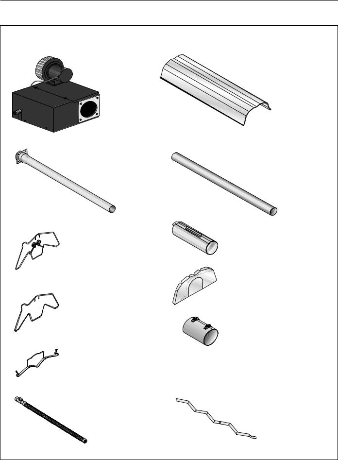
ROBERTS GOR DON® BH-SERI E S SUBM IT TAL SHE E T
BH-SERIES ASSEMBLY OVERVIEW
Major Component Descriptions
Burner with Tube Gasket |
Reflector (Aluminum or |
Must be installed with the |
Stainless Steel) |
flame observation window |
Alternate overlap as shown on |
facing down. |
overview. Minimum overlap is |
|
7” (18 cm). |
|
|
|
|
|
|
|
|
|
|
|
|
Burner Tube |
Tube |
|
|
|
Supplied in 10' (3 m) lengths. |
Hot Rolled or Heat Treated |
|
|
|
Burner tube is always the first |
Aluminized Tube supplied in |
|
|
|
tube after the burner. |
10’ (3 m) lengths. |
|
Tube and Reflector Hanger |
Coupling Assembly with Lock |
|
|
with Clamp Package |
|
Position this hanger no more |
|
than 4” (10 cm) away from |
|
the burner. |
Reflector End Cap |
|
Punch out center section to |
|
accommodate heat exchanger |
Tube and Reflector Hanger |
tube. |
|
|
Suspend system from these |
|
hangers. |
|
|
Vent Adapter |
Reflector Support Strap &
Wire Form
Turbulator
Turbulator must be installed in the last standard section of tube. Turbulator is not required on the
BH-125/150/175/200.
Flex Gas Line with Shut Off Cock
© 2004 Roberts-Gordon BEFORE IN STALLATI ON AND OPER ATI ON OF HEATI NG EQUIPMENT, READ AND U NDERSTAND THE INSTALLATION, OPERATIO N AND SERVICE MANUAL.
APPLICATION S, ENGI NEERING AND DETAI LED GUID ANCE ON SYSTEMS DESIGN, INSTALLATI ON AND PRODUCT PERFORMANCE IS AVAI LABLE UPON REQUEST. ROBERTS GORDON® PRODUCTS ARE TO BE INSTALLED ONLY IN ACCORDANCE WI TH LOCALLAWS, CODES AND REGULATIONS, AND ONLY BY A CONTRACTOR QUALI FIED I N THE I NSTALLATION AND SERVICE OF GAS-FIRED HEATING EQUI PMENT.
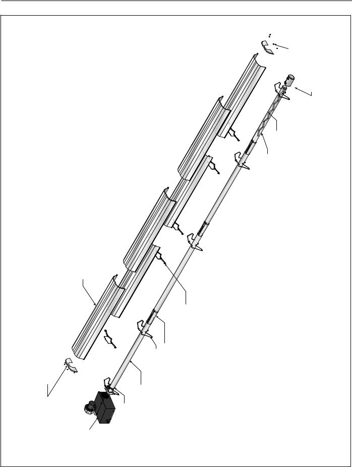
ROBERTS GORDON ® BH-SERI E S SUBM IT TAL SHE E T
BH-Series Linear Assembly Overview
|
|
|
|
|
|
U-Clips |
Adapter |
|
|
|
|
|
|
|
Vent |
|
|
|
|
|
Tube |
Turbulator with select models |
|
Reflector |
|
|
|
|
|
|
|
Reflector End Cap |
|
Burner |
Reflector Hanger |
Coupling |
Reflector Support |
|
|
Burner |
Tube Clamp Package |
Tube and |
|
|
|
|
© 2004 Roberts-Gordon |
BEFORE IN STALLATI ON AND OPER ATI ON OF HEATI NG EQUIPMENT, READ AND U NDERSTAND THE INSTALLATION, OPERATIO N AND SERVICE MANUAL. |
APPLICATION S, ENGI NEERING AND DETAI LED GUID ANCE ON SYSTEMS DESIGN, INSTALLATI ON AND PRODUCT PERFORMANCE IS AVAI LABLE UPON REQUEST. ROBERTS GORDON® PRODUCTS ARE TO BE |
|
|
INSTALLED ONLY IN ACCORDANCE WI TH LOCALLAWS, CODES AND REGULATIONS, AND ONLY BY A CONTRACTOR QUALI FIED I N THE I NSTALLATION AND SERVICE OF GAS-FIRED HEATING EQUI PMENT. |
ROBERTS GOR DON® BH-SERI E S SUBM IT TAL SHE E T
HEATER INSTALLATION
Critical Hanger Placement
Typical Suspension Details
Beam Clamp
24" min.* |
Rod (3/8") |
|
|
(61 cm) |
“X”* |
|
|
Concrete Beam |
Anchor |
Locknut Wood Beam |
Screw Hook |
|
(3/8") |
|
Chain size |
|
3/16" minimum |
Washers |
“S” Hooks |
|
Turnbuckle |
* Allows for thermal expansion of system |
Not Included |
S Hooks |
|
|
Side View |
|
Hanger |
Hanger |
|
|
Reflector |
|
|
Must Be Within 4" (10 cm) |
Front View |
45° Angle |
Description |
Part Number |
S-Hook |
91907302 |
Tube/Reflector Hanger |
03090100 |
Run Length |
Typical Expansion |
Mininum “X” Length |
10’ - 50’ |
±1” (3 cm) |
12” |
51’ - 60’ |
±2” (5 cm) |
18” |
61’ - 80’ |
±3” (8 cm) |
24” |
© 2004 Roberts-Gordon BEFORE IN STALLATI ON AND OPER ATI ON OF HEATI NG EQUIPMENT, READ AND U NDERSTAND THE INSTALLATION, OPERATIO N AND SERVICE MANUAL.
APPLICATION S, ENGI NEERING AND DETAI LED GUID ANCE ON SYSTEMS DESIGN, INSTALLATI ON AND PRODUCT PERFORMANCE IS AVAI LABLE UPON REQUEST. ROBERTS GORDON® PRODUCTS ARE TO BE INSTALLED ONLY IN ACCORDANCE WI TH LOCALLAWS, CODES AND REGULATIONS, AND ONLY BY A CONTRACTOR QUALI FIED I N THE I NSTALLATION AND SERVICE OF GAS-FIRED HEATING EQUI PMENT.
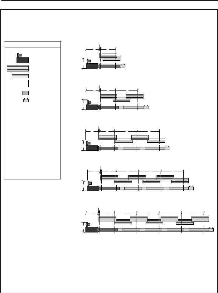
ROBERTS GORDON ® BH-SERI E S SUBM IT TAL SHE E T |
|
|
|
|
|
|
||
BH-Series Linear Layout Overview |
|
|
|
|
|
|
||
|
LEGEND |
|
|
bc |
|
|
|
|
|
|
|
g |
d |
|
|
|
|
|
Burner |
BH-40 |
|
|
|
|
|
|
|
Reflector |
f |
|
|
|
|
|
|
|
|
|
|
|
|
|
|
|
|
Tube |
|
10' Tube Length |
|
|
|
|
|
|
|
|
|
|
|
|
|
|
|
Tube/Reflector |
|
|
bc |
|
|
|
|
|
Hanger |
|
|
|
|
|
|
|
|
Coupling Assembly |
|
g |
d |
e |
|
|
|
|
|
|
|
|
|
|
|
|
|
Vent Adapter |
|
|
|
|
|
|
|
|
|
BH-60 |
f |
|
|
|
|
|
a = |
14" (36 cm) |
BH-80 |
|
|
|
|
|
|
reflector width (not shown) |
|
20' Tube Length |
|
|
|
|
||
|
|
|
|
|
|
|
||
b = |
2" (5 cm) |
|
|
|
|
|
|
|
end cap to burner |
|
|
b c |
|
|
|
|
|
c = |
2" (5 cm) |
|
|
|
|
|
|
|
|
g |
d |
e |
e |
|
|
||
end cap to hanger |
|
|
|
|||||
|
|
|
|
|
|
|
||
d = |
7'6" (229 cm) |
BH-80 |
|
|
|
|
|
|
distance first hanger |
|
|
|
|
|
|
||
e = |
10' (305 cm) |
BH-100 |
f |
|
|
|
|
|
BH-115 |
|
|
|
|
|
|
||
distance between hangers |
|
30' Tube Length |
|
|
|
|
||
f = |
12.5" (32 cm) |
|
|
|
|
|
||
|
|
|
|
|
|
|
||
burner height |
|
|
bc |
|
|
|
|
|
g = |
11" (28 cm) |
|
g |
|
e |
|
e |
|
burner length |
|
d |
e |
|
||||
|
|
BH-100 |
|
|
|
|
|
|
|
|
BH-115 |
|
|
|
|
|
|
|
|
BH-125 |
f |
|
|
|
|
|
|
|
BH-140 |
|
|
|
|
|
|
|
|
|
|
|
|
|
|
|
|
|
|
40' Tube Length |
|
|
|
|
|
|
|
|
|
bc |
|
|
|
|
|
|
BH-115 |
g |
d |
e |
e |
e |
e |
|
|
|
|
|
|
|
|
|
|
|
BH-125 |
|
|
|
|
|
|
|
|
BH-140 |
|
|
|
|
|
|
|
|
BH-150 |
f |
|
|
|
|
|
|
|
BH-175 |
|
|
|
|
|
|
|
|
|
50' Tube Length |
|
|
|
|
|
© 2004 Roberts-Gordon |
BEFORE IN STALLATI ON AND OPER ATI ON OF HEATI NG EQUIPMENT, READ AND U NDERSTAND THE INSTALLATION, OPERATIO N AND SERVICE MANUAL. |
APPLICATION S, ENGI NEERING AND DETAI LED GUID ANCE ON SYSTEMS DESIGN, INSTALLATI ON AND PRODUCT PERFORMANCE IS AVAI LABLE UPON REQUEST. ROBERTS GORDON® PRODUCTS ARE TO BE |
|
|
INSTALLED ONLY IN ACCORDANCE WI TH LOCALLAWS, CODES AND REGULATIONS, AND ONLY BY A CONTRACTOR QUALI FIED I N THE I NSTALLATION AND SERVICE OF GAS-FIRED HEATING EQUI PMENT. |

ROBERTS GOR DON® BH-SERI E S SUBM IT TAL SHE E T
BH-Series Linear Layout Overview (Continued)
|
|
bc |
|
|
|
|
|
|
|
|
g |
d |
e |
e |
e |
e |
e |
|
|
BH-140 |
|
|
|
|
|
|
|
|
|
BH-150 |
f |
|
|
|
|
|
|
|
|
BH-175 |
|
|
|
|
|
|
|
|
|
BH-200 |
|
|
|
|
|
|
|
|
|
|
60' Tube Length |
|
|
|
|
|
|
|
|
|
|
bc |
|
|
|
|
|
|
|
|
g |
d |
e |
e |
e |
e |
e |
e |
|
BH-175 |
f |
|
|
|
|
|
|
|
|
BH-200 |
|
|
|
|
|
|
|
|
|
|
70' Tube Length |
|
|
|
|
|
|
|
|
|
|
bc |
|
|
|
|
|
|
|
|
g |
d |
e |
e |
e |
e |
e |
e |
e |
BH-200 |
f |
|
|
|
|
|
|
|
|
|
80' Tube Length |
|
|
|
|
|
|
|
|
Burner Tube Installation
NOTE:
Tubing requires a downward slope of 1/2" (13 mm)
per 20' (6 m) away from burner.
Offset mounting hole must be to the top
S Hook
Hanger |
Burner Tube
|
7' 6" ± 1' |
|
(229 cm ± 25cm) |
Description |
Part Number |
Burner Tube |
03051XXX |
S-Hook |
91907302 |
Tube/Reflector Hanger |
03090100 |
© 2004 Roberts-Gordon BEFORE IN STALLATI ON AND OPER ATI ON OF HEATI NG EQUIPMENT, READ AND U NDERSTAND THE INSTALLATION, OPERATIO N AND SERVICE MANUAL.
APPLICATION S, ENGI NEERING AND DETAI LED GUID ANCE ON SYSTEMS DESIGN, INSTALLATI ON AND PRODUCT PERFORMANCE IS AVAI LABLE UPON REQUEST. ROBERTS GORDON® PRODUCTS ARE TO BE INSTALLED ONLY IN ACCORDANCE WI TH LOCALLAWS, CODES AND REGULATIONS, AND ONLY BY A CONTRACTOR QUALI FIED I N THE I NSTALLATION AND SERVICE OF GAS-FIRED HEATING EQUI PMENT.
 Loading...