


Rinnai Q85SN, Q85SP, Q175SP, Q205SP, Q175SN User Manual
...I n s t a l l a t i o n & S e r v i c i n g Instructions
High efficiency condensing gas boiler
Q85SN/Q130SN/Q175SN/Q205SN/Q175CN
Q85SP/Q130SP/Q175SP/Q205SP/Q175CP
Pictured: Q85SN, Q130SN
Q85SP, Q130SP
CAUTION!
Read this manual thoroughly before installing, servicing, putting into operation or using this boiler and vent system.
WARNING!
Improper installation, adjustment, alteration, service or maintenance can cause property damage, personal injury (exposure of hazardous materials)* or loss of life. Refer to the user's information manual provided with this boiler. Installation and service must be performed by a licensed professional, service agency or the gas supplier (who must read and follow the supplied instructions before installing, servicing, or removing this boiler).
CAUTION!
The user manual is part of the documentation that is delivered to the installation's operator. Go through the information in this manual with the owner/operator and make sure that they are familiar with all necessary operating instructions.
NOTICE!
Installation and service must be performed by a licensed professional, service technician or the gas supplier.
|
|
|
|
|
WARNING! |
|
|
|
If you do not follow these instructions exactly, a fire or explosion |
|
|
|
may result causing property damage, personal injury or loss of life. |
|
|
|
- Do not store or use gasoline or other flammable vapors and |
|
|
|
liquids in the vicinity of this or any other appliance. |
|
|
|
- WHAT TO DO IF YOU SMELL GAS |
|
|
|
- Do NOT try to light any appliance. |
reserved. |
|
|
- Do NOT touch any electrical switch. |
||
|
|
||
|
- Do NOT use any phone in your building. |
|
|
|
- Immediately call your gas supplier from a neighbor’s phone. |
Changes |
|
|
Follow the gas supplier’s instructions. |
||
|
|
||
|
- If you cannot reach your gas supplier, call the fire department. |
|
|
|
|
|
|
Address: 103 International Drive, Peachtree City, GA, 30269 Toll-free: 1-800-621-9419 • Fax: 678-829-1666 • www.rinnai.us
 8W.51.40.06 / 10.13
These instructions to be retained by user.
Français: voir page 101

Contents of instructions
These installation instructions contain important information for the safe installation, start-up and maintenance of boilers with capacities 85,000 through 205,000 BTU/hr.
These installation instructions are intended for licensed professionals, who have the necessary knowledge and are approved for working on heating and gas systems.
Subject to technical changes
Changes may be made without notice to the illustrations, process steps and technical data as a result of our policy of continuous improvement.
Updating of documentation
Please contact us if you have any suggestions for improvements or corrections.
Find our contact details on the back of this manual.
Installation & Servicing Instructions Rinnai Q-Series
2

Content
1 Safety and general instructions........................................................ |
4 |
||
|
1.1 |
Designated use ................................................................... |
4 |
|
1.2 |
Hazard definitions................................................................ |
4 |
|
1.3 |
Symbol definitions ............................................................... |
4 |
|
1.4 |
The following instructions must be followed ........................ |
5 |
|
1.5 |
Follow these instructions for the space heating water......... |
6 |
|
1.6 |
Tools, materials and additional equipment .......................... |
6 |
|
1.7 |
Relevant Installation, Service and User manuals................ |
6 |
|
1.8 |
Disposal ........................................................................... |
7 |
2 |
Regulations and guidelines.............................................................. |
7 |
|
3 Description of the boiler ................................................................... |
8 |
||
4 |
Packaging and transportation .......................................................... |
9 |
|
|
4.1 |
Scope of delivery................................................................. |
9 |
|
4.2 |
Transportation ..................................................................... |
9 |
5 |
Installation ......................................................................... |
10 |
|
|
5.1 |
Requirements for the installation room............................. |
10 |
|
5.2 |
Fitting the boiler................................................................. |
11 |
|
5.3 |
Dimensions........................................................................ |
12 |
|
5.3.1 |
Plumbing Kits..................................................................... |
15 |
|
5.3.2 |
Clearences from the boiler ................................................ |
16 |
|
5.4 |
Technical specifications..................................................... |
17 |
6 |
Connecting the boiler ..................................................................... |
18 |
|
|
6.1 |
Central heating system...................................................... |
18 |
|
6.1.1 |
Plumbing Kits and installation ........................................... |
20 |
|
6.1.2 |
Side mounting kit for the Low Loss Header....................... |
24 |
|
6.1.3 |
Safety valve....................................................................... |
24 |
|
6.1.4 |
Low water cut off ............................................................... |
24 |
|
6.2 |
Boiler expansion tank ........................................................ |
25 |
|
6.3 |
Underfloor heating system (plastic pipes)........................... |
25 |
|
6.4 |
Gas connection ................................................................. |
26 |
|
6.5 |
Hot water supply (Combi boiler Q175CNQ175CP) ........... |
28 |
|
6.5.1 |
Domestic Water quality...................................................... |
28 |
|
6.5.2 |
Domestic water treatment Accessory ................................ |
29 |
|
6.5.3 |
DHW Expansion Tank........................................................ |
29 |
|
6.5.4 |
Installing a valve kit ........................................................... |
29 |
|
6.5.5 |
Pressure relief Valve for Combi boilers ............................. |
30 |
|
6.6 |
Condensate drain pipe ...................................................... |
30 |
|
6.7 |
Vent system and air supply system ................................... |
31 |
|
6.7.1 |
Intake / Exhaust Guidelines............................................... |
31 |
|
6.7.2a |
Examples vent and air supply systems (concentric) ......... |
32 |
|
6.7.2b |
Examples vent and air supply systems (parallel) .............. |
33 |
|
6.7.3 |
Installation of the vent system ........................................... |
34 |
|
6.7.3.1 |
Boiler conversion from concentric to parallel .................... |
35 |
|
6.7.3.2 |
Installing air filter ............................................................... |
35 |
|
6.7.4 |
Recommended vent/air intake terminal position ............... |
36 |
|
6.7.5 |
Direct vent closet and alcove installation ........................ |
38 |
|
6.7.6 |
Dimensioning of the exhaust and air intake duct ............. |
39 |
|
6.7.7 |
Combustion air and vent piping lengths. ........................... |
40 |
|
6.7.8 |
Calculation of compensation factor ................................... |
41 |
|
6.7.9 |
Room Air System (indoor combustion air)......................... |
42 |
7 |
External domestic hot water tanks ................................................. |
45 |
|
8 |
Electrical connections .................................................................... |
45 |
|
9 |
Boiler controls ......................................................................... |
49 |
|
|
9.1 |
Explanation of the function buttons ................................... |
50 |
10 |
Starting up: Filling and de-aerating the boiler and installation ....... |
51 |
|
|
10.1 |
Requirements of the water system.................................... |
51 |
|
10.2 |
Filling the heating system.................................................. |
52 |
|
10.3 |
Hot water supply (only Q175C) ......................................... |
53 |
11 |
Adjustments ......................................................................... |
55 |
|
|
11.1 |
Altering adjustments.......................................................... |
55 |
|
11.2 |
Activating factory settings (green button function) ........... |
58 |
12 |
Isolating the boiler......................................................................... |
58 |
|
13 |
Commissioning ......................................................................... |
59 |
|
|
13.1 |
Testing for gas leaks.......................................................... |
60 |
|
13.2 |
Testing the Ignition Safety shut off device ......................... |
60 |
|
13.3 |
Checking the O2................................................................. |
61 |
|
13.4 |
Measuring the ionization current ....................................... |
62 |
|
13.5 |
Installing the casing........................................................... |
63 |
14 |
Maintenance ......................................................................... |
63 |
|
|
14.1 |
Periodic examination of venting systems and boiler ......... |
63 |
|
14.2 |
Inspection ......................................................................... |
63 |
|
14.3 |
Maintenance activities ....................................................... |
65 |
|
14.3.1 |
Reset service interval counter ........................................... |
67 |
|
14.4 |
Limited warranty ................................................................ |
67 |
15 |
Parts of the boiler ......................................................................... |
68 |
|
16 |
Blocks and Errors ......................................................................... |
69 |
|
17 |
Spare parts ......................................................................... |
77 |
|
18 |
Parts list vent system ..................................................................... |
89 |
|
19 |
Common venting guidelines........................................................... |
90 |
|
Appendix A - Outoor Reset Sensor Data ............................................. |
91 |
||
Appendix B - Resistance table NTC sensors....................................... |
92 |
||
Installation & Servicing Instructions Rinnai Q-Series
3

Installation & Servicing Instructions Rinnai Q-Series
1 Safety and general instructions
Please observe these instructions in the interest of your own safety.
1.1 Designated use
The boiler is designed for heating water for a central heating system and, if applicable, generating domestic hot water. The boiler is delivered with a burner controller (MCBA) pre-installed.The boiler can be fitted with a modulating outdoor reset sensor ARV12 (included with the boiler) or an On/Off thermostat or relay panel end switch (accessories).
1.2 Hazard definitions
|
The following defined terms are used throughout the documentation to bring attention |
|
to the presence of hazards of various risk levels. Notices give important information |
|
concerning the operation of the product. |
! DANGER |
DANGER: |
|
Indicates the presence of hazards that will cause severe personal injury, death or |
|
substantial property damage. |
!WARNING
!CAUTION
 CAUTION
i NOTICE
WARNING:
Indicates the presence of hazards that can cause severe personal injury, death or substantial property damage.
CAUTION:
Indicates presence of hazards that will or can cause minor personal injury or property damage.
CAUTION:
Risk of electric shock. Indicates presence of hazards due to electric shock.
NOTICE:
Indicates special instructions on installation, operation or maintenance that are important but not related to personal injury or property damage.
1.3 Symbol definitions
The following (safety) symbols may be encountered in these installation instructions and on the unit:
Thissymbolindicatesthattheunitmustbestoredawayfromfreezingconditions.
This symbol indicates that the packaging and/or contents can be damaged as a result of insufficient care taken during transport.
This symbol indicates that, while still in its packaging, the unit must be protected from weather conditions during transport and storage.
4

1.4The following instructions must be followed
-The boiler must only be used for its designated purpose, as described in the Installation Instructions.
-Each unit is fitted with a data plate. Consult the details on this plate to verify whether the boiler is compliant with its intended location, e.g.: gas type, power source and venting classification.
-Only use the boiler with the accessories and spare parts listed.
-Other combinations, accessories and consumables may only be used if they are specifically designed for the intended application and do not affect the system performance and the safety requirements.
-Maintenance and repairs must be performed by a licensed professional.
-Installation of a condensing gas boiler must be reported to the relevant gas utility company and have it approved.
-You are only allowed to operate the condensing gas boiler with the vent system that has been specifically designed and approved for this type of boiler.
-Please note that local permission for the vent system and the condensate water connection to the public sewer system may be required.
You must also respect:
-The local building codes stipulating the installation rules.
-The local building codes concerning the air intake and outlet systems and the chimney connection.
-The regulations for the power supply connection.
-The technical rules established by the gas utility company concerning the connection of the gas connection to the local gas mains.
-The instructions and standards concerning the safety equipment for the water/ space heating system.
-The Installation Instructions for building heating systems.
-The boiler must be located in an area where leakage of the boiler or connections will not result in damage to the area adjacent to the boiler or to lower floors of the structure. When such locations cannot be avoided, it is recommended that a suitable drain pan be installed under the boiler.
-The boiler must be installed in such way that the all components are protected from water (dripping, spraying, rain etc.) during boiler operation and service.
-The boiler must not be installed on or against carpeting.
-Do not restrict or seal any air intake or outlet openings.
-If you find any defects, you must inform the owner of the system of the defect and the associated hazard in writing.
!
!
WARNING
DANGER
In failure to properly commission the boiler as described in section 13 may result unreliable burner operation, reduced component life, and unsafe boiler operation.
DANGER. Gas is flammable and may cause an explosion. Beware if you smell gas: there may be an explosion hazard!
If the information in these instructions is not followed exactly, a fire or explosion may result causing property damage, personal injury or death.
-Do not store or use gasoline or other flammable vapors and liquids in the vicinity of this or any other appliance.
! |
WARNING |
WHAT TO DO IF YOU SMELL GAS |
|
|
- Do NOT try to light any appliance. |
|
|
- Do NOT touch any electrical switch. |
|
|
- Do NOT use any phone in your building. |
|
|
- Immediately call your gas supplier from a neighbor’s phone. Follow the gas |
|
|
supplier’s instructions. |
|
|
- If you cannot reach your gas supllier, call the fire department. |
! |
WARNING |
Should overheating occur or the gas supply fail to shut off, do not turn off or |
disconnect the electrical supply to the pump. Instead, shut off the gas supply |
||
|
|
at a location external to the boiler. |
Installation & Servicing Instructions Rinnai Q-Series
5

Installation & Servicing Instructions Rinnai Q-Series
i NOTICE |
Chemicals that are corrosive in nature should not be stored or used near the |
boiler or vent termination. |
1.5 Follow these instructions for the space heating water
Unsuitable heating system water can cause the formation of scale or sludge, which affects system efficiency. It can also cause corrosion and reduce life of the heat exchanger.
–You must follow Rinnai guidelines for boiler water quality.
–Thoroughly flush the system prior to filling.
–Follow the Rinnai cleaning instructions.
–Never use water that has been treated by a reverse osmosis, D.I., or distilled water to soften the water to fill the heating system.
–Do not use inhibitors or other additives unless approved by Rinnai for that purpose.
–When freeze protection of the heating system is desired, only use Rinnai-approved antifreezes. The allowed maximum concentration is 50%.
–When using oxygen-permeable pipes, e. g. for under floor heating systems, you must separate the system from the boiler using plate heat exchangers.
–Valve off boiler while flushing system, do not introduce any system cleaner into the boiler loop. Flush system thoroughly to remove all system cleaner before filling boiler.
Approved antifreeze: |
• Rhomar RhoGard Mutli-Metal (AL safe) |
• Sentinel X500 |
(max. concentration 50%) |
• Noble Noburst AL |
• Fernox Alphi 11 |
Approved system cleaner: |
• Noble Noburst Hydronic System Cleaner |
• Fernox F3 Cleaner |
|
• Rhomar Hydro-Solv 9100 |
• Sentinel X400 |
i |
NOTICE |
The system cleaners from NoBurst, Rhomar, and Fernox are not to be used in |
||
the boiler. The boiler must be closed off (valved off) from the rest of the system |
||||
|
|
or not connected while the cleaners are in the system. The system should then |
||
|
|
be drained and then thoroughly flushed with clean water to remove all the |
||
|
|
system cleaner. |
|
|
|
Approved inhibitors: • Rhomar Pro-tek 922 |
• Sentinel X100 |
||
|
|
• Noble Noburst AL inhibitor |
|
|
|
|
|
||
|
|
See the Rinnai Boiler Applications Manual or Chapter 6 and 10 of this manual for |
||
|
|
additional information. |
|
|
|
|
|
||
i |
NOTICE |
If problems occur when using sanitary water with a chlorine content |
||
higher than 150 mg/l, no recourse can be made to the terms of the limited |
||||
|
|
|||
warranty.
1.6 Tools, materials and additional equipment
For the installation and maintenance of the boiler you will need:
–Standard tools for space heating, gas and water fitting
–Digital manometer that is capable of reading both positive and negative pressures
–Combustion analyzer (intended for use with condensing boilers)
–Digital multimeter
–pH digital meter
–Metric Allen wrenches
–Metric socket wrenches
In addition, a handtruck with a fastening belt is useful.
For maintenance of the boiler you will need, apart from standard tools for space heating, gas and water fittings the following items:
-Rinnai toolkit Q and E-Series
6

1.7Relevant Installation, Service and User manuals
–Approved vent system
–Rinnai Boiler Applications Manual
–User manual
1.8Disposal
–Dispose of the boiler packaging in an environmentally sound manner.
–Dispose of components of the heating system (e.g. boiler or control device), that must be replaced in an environmentally responsible manner.
2 Regulations and guidelines
The installation must comply to the requirements of the authority having jurisdiction or, in the absence of such requirements, to the latest edition of the National Fuel Gas Code, ANSI Z223.1/NFPA 54. In Canada, installation must be in accordance with the requirements of CAN/CSA B149.1, Natural Gas and Propane Installation Code.
Where required by the authority having jurisdiction, the installation must comply to the Standard for Controls and Safety Devices for Automatically Fired Boilers, ANSI/ ASME CSD-1.
Install CO detectors per local regulations. Boiler requires an inspection every 2 years or 4000 hours and maintenance every 4 years or 8000 hours. See maintenance section chapter 14.
Operating Limits of the boiler:
Max. boiler temperature: 176 °F (80 °C)
Max. operating pressure: 45 psi (3 bar)
Max. Allowable Working Temperature ASME: 200 °F (93 °C)
Max. Allowable Working Pressure ASME: 45 psi (3 bar)
The hot water distribution system must comply with all applicable codes and regulations. When replacing an existing boiler, it is important to check the condition of the entire hot water distribution system to ensure safe operation.
Installation & Servicing Instructions Rinnai Q-Series
7
3 Description of the boiler
Room sealed boiler
The boiler retreives its combustion air from outside then discharges the flue gasses to the outside.
Condensing
Retrieves heat as much as possible from the flue gasses.
Water condensates on the heat exchanger.
Modulating
Stepless higher or lower burning according to the heat demand.
Different boilertypes:
The Rinnai Q boiler is a room sealed, condensing and modulating central heating boiler, with an optional integrated DHW cylinder (integrated DHW on the Q175C only). The QxxS boiler models have the ability to control a domestic hot water indirect tank.
The boiler is provided with a compact stainless steel heat exchanger with smooth tubes. This design is a well engineered principle using durable materials.
The boiler burns gas for supplying heat. The heat is transferred in the heat exchanger to the water in the central heating system. By cooling down the exhaust gases condensate is formed. This results in high efficiency. The condensate, which has no effect on the heat exchanger and the function of the boiler, is drained through a condensate collector trap.
The boiler is provided with an intelligent control system (CMS Control Management System). The boiler anticipates the heat demand of the central heating system or the domestic hot water facility system.
When an outdoor sensor is connected to the boiler it will operate weather dependantly using outdoor reset. This means that the boiler control measures the outside temperature and supply temperature. With this data the boiler calculates the optimal supply temperature for the installation.
Explanation of the type indication: |
Rinnai Q205SN |
||||||||||||||||||||||||
|
|
|
|
Q = Type |
|
|
|
|
|
|
|
|
|
|
|
|
|
|
|
|
|
||||
|
|
|
|
|
|
|
|
|
|
|
|
|
|
|
|
|
|||||||||
|
|
|
|
|
|
|
|
|
|
|
|
|
|
|
|
|
|||||||||
|
|
|
|
205 = Nominal load in (x1,000) BTU |
|
|
|
|
|
|
|
|
|
|
|
||||||||||
|
|
|
|
||||||||||||||||||||||
|
|
|
|
S = System/Solo (C = Combi) |
|
|
|
|
|
|
|
|
|
|
|
|
|
|
|||||||
|
|
|
|
N = Natural Gas (P = Propane Gas) |
|
||||||||||||||||||||
|
|
|
|
|
|
|
|
|
|
|
|
|
|
|
|
|
|
|
|
|
|
|
|
|
|
|
|
|
|
|
|
|
|
|
|
|
|
|
|
|
|
|
|
|
|
|
|
|
|
|
|
|
|
|
|
|
|
|
|
|
|
|
|
|
|
|
|
|
|
|
|
|
|
|
|
|
|
|
|
|
|
|
|
|
|
|
|
|
|
|
|
|
|
|
|
|
|
|
|
|
|
|
|
|
|
|
|
|
|
|
|
|
|
|
|
|
|
|
|
|
|
|
|
|
|
|
|
|
|
|
|
|
|
|
|
|
|
|
|
|
|
|
|
|
|
|
|
|
|
|
|
|
|
|
|
|
|
|
|
|
|
|
|
|
|
|
|
|
|
|
|
|
|
|
|
|
|
|
|
|
|
|
|
|
|
|
|
|
|
|
|
|
|
|
|
|
|
|
|
|
|
|
|
|
|
|
|
|
|
|
|
|
|
|
|
|
|
|
|
|
|
|
|
|
|
|
|
|
|
|
|
|
|
Installation & Servicing Instructions Rinnai Q-Series
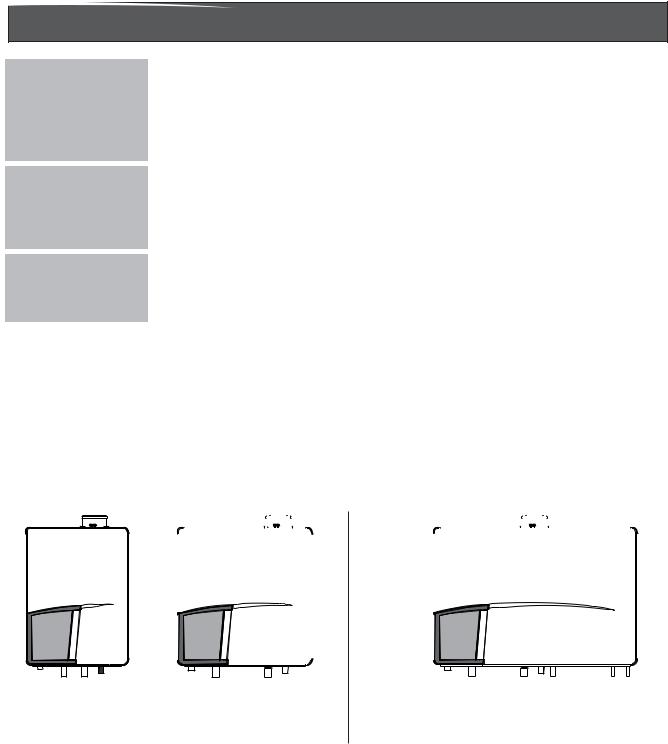
System/Solo boilers: |
|
Q85SN, Q130SN |
Q175SN, Q205SN |
Q85SP, Q130SP |
Q175SP, Q205SP |
Combi boiler with integrated DHW cylinder Q175CN
Q175CP
8

4 Packaging and transportation
4.1 Scope of delivery
The boiler is supplied ready for use.
•Please check if the packaging is intact.
•Check if all the items listed are included in the delivery.
The supply kit contents:
|
Description |
|
Amount |
|
|
|
|
Q85S |
Q175S |
|
|
|
|
Q130S Q205S Q175C |
|
||
|
Boiler with: |
|
|
|
|
|
Outdoor reset sensor ARV12 |
1 |
1 |
1 |
|
|
Compression ring Ø15 brass |
|
|
4 |
|
|
Compression ring Ø22 brass |
|
|
2 |
|
|
Compression ring Ø28 brass |
2 |
|
|
|
|
Compression ring Ø35 brass |
|
2 |
2 |
|
|
Bolt M5X16mm |
1 |
1 |
1 |
|
|
Cover air supply Ø120/Ø80 |
1 |
1 |
1 |
|
|
Gasket vent system ø80 |
1 |
1 |
1 |
|
|
Power cable pull safety Q-Series |
1 |
1 |
1 |
|
|
Flue pipe Ø 80 PP |
1 |
1 |
1 |
|
|
Nut 15mm compression fitting |
|
|
2 |
|
|
Nut W1.1/8x1/14 22 Compression fitting |
|
|
1 |
|
|
Nut W1.3/8"x1/14 28 compression fitting |
2 |
|
|
|
|
Nut W1.610x1/14 35 compression fitting |
|
2 |
2 |
|
|
Screw 6X60mm |
5 |
5 |
5 |
|
|
Lip-ring flue pipe ø80 |
1 |
1 |
1 |
|
|
Feed through + plug flue gas |
1 |
1 |
1 |
|
|
Cap de-aerator |
1 |
1 |
1 |
|
|
Adapter fitting 15mm x 3/4"NPT ext. |
|
|
2 |
|
|
Adapter fitting 22mm x 3/4"NPT ext. |
|
|
1 |
|
|
Flue adapter Ø80/Ø3" pps UL appr. |
2 |
2 |
2 |
|
|
Flow restriction MR01 FG 21,0L red |
|
|
1 |
|
|
Wall mounting suspension bracket |
1 |
1 |
1 |
|
|
Plumbing kit Q85S/Q130S |
1 |
1 |
|
|
|
Plumbing kit Q175S/Q175C/Q205S |
|
|
1 |
|
|
3/4" Gas valve |
1 |
1 |
1 |
|
|
Template on inside of package |
1 |
1 |
1 |
|
|
Installation & Service Instructions |
1 |
1 |
1 |
|
|
User information manual |
1 |
1 |
1 |
|
|
Warranty document |
1 |
1 |
1 |
|
|
ICSL book |
1 |
1 |
1 |
|
|
|
|
|
|
|
4.2 Transportation |
|
|
|
|
|
! CAUTION |
The boiler may be damaged when not secured properly. |
|
|
||
-Only transport the boiler using appropriate transportation equipment, such as a handtruck with a fastening belt or special equipment for maneuvering steps.
-When shipping the boiler must be secured on the transportation equipment to prevent it from falling off.
-Protect all parts against impacts if they are to be transported.
-Follow the transportation markings on the packaging.
•Packaged boilers must always be lifted and carried by two people, or you must use a handtruck or special equipment for transport.
Installation & Servicing Instructions Rinnai Q-Series
9

Installation & Servicing Instructions Rinnai Q-Series
5Installation
5.1Requirements for the installation room
! DANGER |
- The room where the boiler will be placed must always be free from freezing |
conditions. |
-Do not store or use gasoline or other flammable vapors and liquids in the vicinity of this or any other appliance.
-Never use or store any chlorinated detergents or halogenated hydrocarbons (e.g. in spraycans, solvents and detergents, paints, adhesives) in proximity of the boiler.
-The boiler must be installed in such a way that it is protected from water (dripping, spraying, rain, etc.) during operation and service (circulator replacement, condensate trap, control replacement, etc.)
-This boiler is for intended for indoor installations only.
Products to avoid present in boiler room and/or around combustion air intake
Spray cans containing chloro-/fluorcarbons Ammonium and/or ammonium solutions Permanent wave solutions (hair product) Chlorinated waxes and/or cleaners Swimming pool chemicals based on chlorine Calcium chloride used for thawing
Sodium chloride used for water softening Refrigerant leaks
Paint or varnish removers Hydrochloric acid/muriatic acid Cements and glues
Antistatic fabric softeners used in clothes dryers Chlorine-type bleaches, detergents, and cleaning solvents found in household laundry rooms
Adhesives used to fasten building products and other similar products
Areas likely to have contaminants
Dry cleaning/laundry areas and establishments
Swimming pools
Metal fabrication plants
Beauty shops
Refrigeration repair shops
Photo processing plants
Auto body shops
Plastic manufacturing plants
Furniture refinishing areas and establishments
New building construction
Remodeling areas
Garages with workshops
10
5.2 Fitting the boiler
i
i
!
!
NOTICE
NOTICE
CAUTION
WARNING
-Remove the packaging materials.
-Do not tear the packaging. Take notice of the presence of the mounting template at the inside of the carton wrapper.
-Lay the boiler on its back during unpacking. When unpacking, the casing can be removed from the boiler. This part can be kept apart during installation. It must be placed on the boiler and fixed with the screw behind the door before the boiler is started up.
Turn the boiler to its side and remove the wall bracket from the back of the boiler by removing the 2 screws.
The boiler can be mounted practically to any wall with the suspension bracket and the enclosed mounting equipment.
-The wall must be flat and of sufficient strength in order to be able to securely hold and support the boiler weight with its water content.
-Take note of the necessary space around the boiler for installation of venting system, pipework and servicing. See drawing in section 5.3.
The location of the boiler can be determined by using the template which is printed on the inside the boiler package wrapping. Remember to account for the spacing of the plumbing kit.
-Drill the necessary holes using the template
-Install the mounting bracket to the wall using the supplied mounting materials
Lifting and carrying precautions.
To avoid personal injury please follow these recommendations:
-Always lift the boiler with 2 people or use special equipment.
-When lifting the boiler, bend the knees, and keep the back straight and feet apart.
-Do not lift and twist at the same time.
-Lift and carry the boiler close to the body.
-Wear protective clothing and gloves to protect from any sharp edges.
Lift the boiler only by the boiler's rear wall. Do not lift using the pipes on the bottom of the boiler or the vent connections on the top of the boiler.
-Dispose the packaging materials.
Installation & Servicing Instructions Rinnai Q-Series
11

Installation & Servicing Instructions Rinnai Q-Series
5.3 Dimensions
|
|
F |
C |
|
|
D |
|
|
|
F |
C |
|
D |
|
|
|
|
E |
|
|
|
|
|
E |
|
|
|||||
|
|
|
|
|
|
|
|
|
|
|
|
|
W |
||
|
|
|
|
|
|
|
|
|
|
|
|
|
|
|
|
|
A |
|
|
|
|
|
|
|
|
A |
|
|
|
|
|
|
P |
|
|
|
G |
|
|
|
Q |
P |
|
|
G |
|
Q |
|
|
X |
|
|
|
|
|
X |
|
|
|
||||
Y |
T |
|
|
K |
|
|
Y |
T |
|
|
|
||||
U |
|
|
|
|
|
|
U |
|
|
|
|
K |
|||
|
V1 |
|
|
|
|
|
|
|
|
V1 |
|
|
|
|
|
R |
|
|
|
|
|
|
|
|
R |
|
|
|
|
|
|
|
|
V2 |
|
|
H |
|
Z |
|
|
V2 |
|
H |
|
|
|
|
|
aa |
|
|
|
|
J |
B |
|
|
aa |
|
J |
|
|
|
|
|
|
|
|
|
|
|
|
B |
|||||
|
|
|
|
|
|
|
|
|
|
|
|
|
|
|
|
dimensions Q85S, Q130S, Q175S and Q205S |
|
|
|
|
|
|
|
|
figure 1 |
||||||
|
|
|
|
|
F |
C |
|
|
D |
|
|
|
|
|
|
|
|
|
|
|
E |
|
|
|
|
|
|
|
|
||
|
|
|
|
|
|
|
|
|
|
|
|
|
|
|
|
|
|
|
|
A |
|
|
|
|
|
|
|
|
|
|
|
|
|
|
|
P |
|
X |
|
G |
|
|
|
|
|
Q S |
|
|
|
|
Y |
T |
|
|
|
K |
|
|
|
|
|
|
|
|
|
|
U |
|
|
|
|
|
|
|
|
|
|
||
|
|
|
|
V1 |
|
|
|
|
|
|
|
|
|
|
|
|
|
|
R |
|
|
|
|
|
|
|
|
|
|
|
|
|
|
|
|
|
V2aa |
|
|
H |
J |
Z |
|
|
|
|
|
|
|
|
|
|
|
|
|
|
|
|
|
|
|
||
|
|
|
|
|
|
|
|
|
L N |
O B |
|
|
|
|
|
|
|
|
|
|
|
|
|
|
|
|
|
|
|
|
|
dimensions Q175C |
figure 2 |
12

Dimensions
|
|
Boiler type |
Solo |
Combi |
|
|
|
|
|
Q85SN/Q85SP |
Q175SN/Q175SP |
|
|
|
|
|
Q130SN/Q130SP |
Q205SN/Q205SP |
Q175CN/Q175CP |
|
|
|
|
inch / mm |
inch / mm |
inch / mm |
|
|
A |
Height |
26.8" / 680 |
26.8" / 680 |
26.8" / 680 |
|
|
B |
Width |
19.7" / 500 |
26" / 660 |
39.4" / 1000 |
|
|
C |
Depth |
15.2" / 385 |
15.2" / 385 |
15.2" / 385 |
|
|
D |
Left side / vent |
13.2" / 335 |
19.5" / 495 |
19.5" / 496 |
|
|
E |
Center to center / vent and air supply |
4.7" / 120 |
4.7" / 121 |
4.7" / 122 |
|
|
F |
Back / vent |
10.6" / 270 |
10.6" / 270 |
10.6" / 270 |
|
|
G |
Left side / gas pipe |
2.6" / 65 |
2.6" / 65 |
2.6" / 65 |
|
|
H |
Left side / supply pipe |
7.8" / 199 |
7.8" / 199 |
7.8" / 199 |
|
|
J |
Left side / return pipe |
16.8" / 428 |
19.8" / 504 |
19.8" / 504 |
|
|
K |
Left side / condensate pipe |
14.6" / 370 |
20.9" / 530 |
20.9" / 530 |
|
|
L |
Left side / expansion pipe |
|
|
23.2" / 590 |
|
|
N |
Left side / cold water pipe |
|
|
34.8" / 885 |
|
|
O |
Left side / hot water pipe |
|
|
37.6" / 955 |
|
|
P |
Pipe length of g* |
0.7" / 18 |
0.7" / 18 |
0.7" / 18 |
|
|
Q |
Pipe length of c* |
2" / 50 |
2" / 50 |
2" / 50 |
|
|
R |
Pipe length of f and r* |
17.7" / 450 |
18.5" / 470 |
18.5" / 470 |
|
|
S |
Pipe length of e, k and w* |
|
|
3.5" /89 |
|
|
T |
Back / Center of pipe c* |
1" / 25 |
1" / 25 |
1" / 25 |
|
|
U |
Back / Center of pipe g* |
1.6" / 40 |
1.6" / 40 |
1.6" / 40 |
|
|
V1 |
Back / Center of pipe f, r, e, k and w* |
2" / 50 |
2" / 50 |
2" / 50 |
|
|
V2 |
Back / Center of pipe f and r* |
2.1" / 54 |
2.1" / 54 |
2.1" / 54 |
|
|
W |
Pipe length vent co-axial |
2.6" / 65 |
2.6" / 65 |
2.6" / 65 |
|
|
|
Pipe length vent parallel |
5.8" / 147 |
5.8" / 147 |
5.8" / 147 |
|
|
X |
Bottom side boiler to center safety valve |
7.7" / 195 |
8" / 200 |
8" / 200 |
|
|
Y |
Bottom side boiler to center header |
10.2" / 260 |
10.4" / 265 |
10.4" / 265 |
|
|
Z |
Center to center of f and r* |
9" / 229 |
12" / 305 |
12" / 305 |
|
|
aa |
Depth plumbing kit |
5.6" / 142 |
5.6" / 142 |
5.6" / 142 |
|
|
|
*) See figure 3 |
|
|
|
|
dimensions |
|
|
table 1 |
|||
Installation & Servicing Instructions Rinnai Q-Series
13
Dimensions
Connection for combustion air supply and vent system
g f1 r1 c |
g f1 |
r1 |
c |
g f1 |
r1 |
c |
e |
k w |
t 


f2 |
r2 |
f2 |
r2 |
f2 |
r2 |
|
boiler connections |
|
|
|
|
figure 3 |
|
Installation & Servicing Instructions Rinnai Q-Series
|
|
Boiler type |
Solo |
Combi |
|
|
|
|
|
Q85SN/Q85SP |
Q175SN/Q175SP |
|
|
|
|
|
Q130SN/Q130SP |
Q205SN/Q205SP |
Q175CN/Q175CP |
|
|
|
|
|
|
|
|
|
Vent system / Combustion air supply |
80/125mm |
80/125mm |
80/125mm |
||
|
Gas pipe |
g |
3/4"M-NPT |
3/4"M-NPT |
3/4"M-NPT |
|
|
Supply pipe |
boiler side - f1 |
28mm |
35mm |
35mm |
|
|
|
system side - f2 |
1¼"M-NPT |
1½"M-NPT |
1½"M-NPT |
|
|
Return pipe |
boiler side - r1 |
28mm |
35mm |
35mm |
|
|
|
system side - r2 |
1¼"M-NPT |
1½"M-NPT |
1½"M-NPT |
|
|
Condensate pipe |
c |
0.95" / 24mm |
0.95" / 24mm |
0.95" / 24mm |
|
|
Expansion pipe |
e |
|
|
0.87"x ¾"M-NPT / |
|
|
|
|
22mm |
|||
|
|
|
|
|
||
|
Cold water pipe |
k |
|
|
0.6"x ¾"M-NPT / |
|
|
|
|
15mm |
|
||
|
|
|
|
|
|
|
|
Hot water pipe |
w |
|
|
0.6"x ¾"M-NPT / |
|
|
|
|
15mm |
|||
|
|
|
|
|
||
|
Supply pipe indirect tank. |
|
|
|
|
|
|
In case of optional internal |
t |
1"M-NPT |
|
|
|
|
3 way valve. |
|
|
|
|
|
connection diameters |
|
|
|
table 2 |
||
14
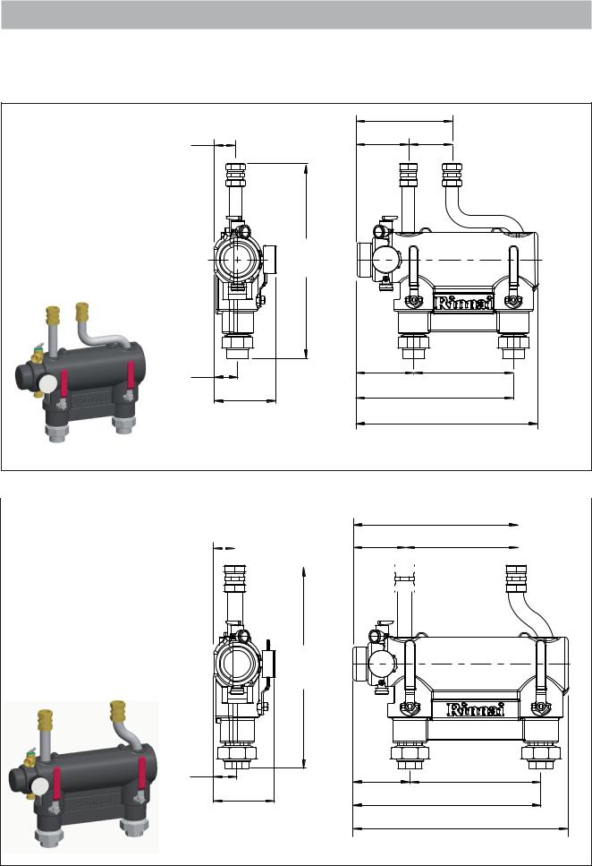
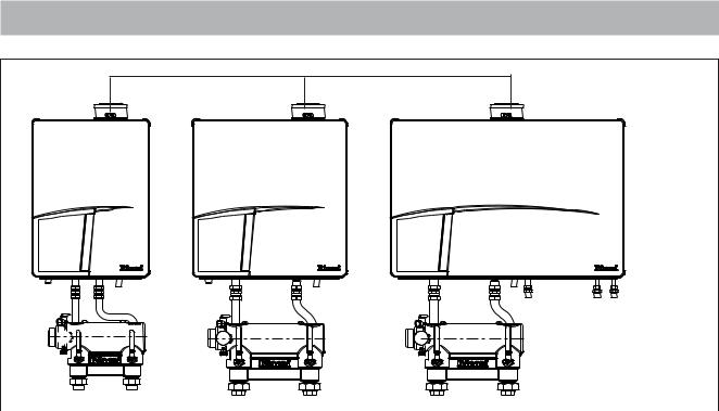
5.3.1Plumbing Kits
Rinnai boilers are supplied with a Plumbing kit from factory. Find below the dimensions.
See chapter 6.1 for additional information.
|
|
8.6” |
||
Plumbing Kit 2 |
2.0” |
219mm |
||
Suitable for: |
4.7” |
3.9” |
||
50mm |
119mm |
100mm |
||
Q85SN / Q85SP |
||||
|
|
|
||
Q130SN / Q130SP |
|
|
|
|
|
17.6” |
|
|
448mm |
|
2.1” |
5.2” |
9” |
54mm |
131mm |
229mm |
142 |
|
14.2” |
[5.6”] |
360mm |
|
|
|
16.4” |
|
|
416mm |
Plumbing kit 2 |
|
|
|
|
|
|
|
|
|
|
|
|
|
|
|
|
|
|
|
|
figure 4 |
|
|
|
|
|
|
|
|
|
|
|
|
|
|
|
|
|
|
||||
|
|
|
|
|
|
|
|
|
|
|
|
|
|
|
15” |
|
|
||||
|
|
|
|
|
|
|
|
|
|
|
|
|
|
|
|
||||||
Plumbing Kit 3 |
2.0” |
|
|
|
|
|
4.7” |
|
381mm |
|
|
||||||||||
Suitable for: |
|
|
|
|
|
|
|
|
|
|
|
10.2” |
|
|
|||||||
|
|
|
|
|
|
|
|
|
|
|
|||||||||||
|
|
|
|
|
|
|
|
|
|
|
|
|
|
|
|
|
|
|
|
|
|
50mm |
|
|
|
|
|
120mm |
|
|
|
|
|
|
260mm |
|
|
|
|||||
Q175SN / Q175SP |
|
|
|
|
|
|
|
|
|
|
|
|
|
||||||||
|
|
|
|
|
|
|
|
|
|
|
|
|
|
|
|
|
|
|
|
|
|
Q175CN / Q175CP |
|
|
|
|
|
|
|
|
|
|
|
|
|
|
|
|
|
|
|
|
|
|
|
|
|
|
|
|
|
|
|
|
|
|
|
|
|
|
|
|
|
|
|
Q205SN / Q205SP |
|
|
|
|
|
|
|
|
|
|
|
|
|
|
|
|
|
|
|
|
|
|
|
|
|
|
|
|
|
|
|
|
|
|
|
|
|
|
|
|
|
|
|
|
18.6” |
|
|
|
Q-Series |
|
|
|
|
RinnaiInstructions |
|
|
474mm |
|
|
|
|
|
|
|
|
|
|
2.1” |
5.2” |
438mm |
19.7” |
|
Servicing& |
54mm |
133mm |
|
305mm |
|
|
[5.6” |
17.2” |
|
|
||
142mm |
|
|
|
|
|
|
|
|
|
Installation |
|
|
|
501mm |
|
||
|
|
|
|
||
Plumbing kit 3 |
|
|
|
figure 5 |
|
15

5.3.2Clearences from the boiler
ceiling |
|
|
|
|
Min. 10" / |
|
|
|
|
250mm |
|
2" |
2" |
|
15.7" |
24" |
|||
50 |
50 |
|||
400 |
600 |
|||
|
|
|||
wall |
|
|
|
Installation & Servicing Instructions Rinnai Q-Series
|
|
|
|
|
|
|
|
|
service clearances to the boiler |
|
|
|
figure 6 |
||||
|
|
|
|
|
|
|
||
|
|
|
Minimum required clearances |
Minimum required clearances |
Recommended |
|||
|
|
|
to combustibles |
|
to non-combustibles |
service clearances |
|
|
|
|
|
All types |
|
All types |
All types |
|
|
|
|
|
inch / mm |
|
inch / mm |
inch / mm |
|
|
Top of boiler |
2" / 50 |
2" / 50 |
10" / |
250 |
|
|||
Back of boiler |
0" |
0" |
0 |
|
|
|||
Front of boiler |
6" / 150 |
6" / 150 |
24" / |
600 |
|
|||
Left side of boiler |
2" / 50 |
2" / 50 |
2" / |
50 |
|
|||
Right side of boiler |
2" / 50 |
2" / 50 |
2" / |
50 |
|
|||
Floor / Ground to |
12" / 300 |
12" / 300 |
30" / |
762 |
|
|||
bottom of boiler |
|
|||||||
|
|
|
|
|
|
|||
Floor/ Ground to |
|
|
|
|
|
|
|
|
bottom Low loss |
|
0" |
0" |
12" / |
300 |
|
||
header |
|
|
|
|
|
|
|
|
Vent |
|
0" |
0" |
0" |
|
|||
clearances to the boiler |
|
|
|
|
table 3 |
|||
For closet installation: clearance is 1” / 25mm from the front.
Low Loss Header
Clearances to combustible and non-combustible is 0 inch for sides, top, front and floor/ground The recommended service clearance to the bottom of the low loss header is 12 inches.
16

5.4 Technical specifications
|
|
|
|
|
|
|
Q-Series |
|
|
|
|
|
|
|
|
|
Combi |
|
|
|
|
|
|
|
|
|
|
|
Q175CN |
Q85SN |
Q130SN |
Q175SN |
Q205SN |
|
|
|
Boiler type |
|
|
Q175CP |
Q85SP |
Q130SP |
Q175SP |
Q205SP |
|
|
|
|
|
|
|
|
|
|
|
|
|
|
|
|
Input Hs CH |
BTU/hr |
175,000 |
85,000 |
130,000 |
175,000 |
205,000 |
|
|
||
|
|
|
kW |
|
51 |
25 |
38 |
51 |
60 |
|
|
|
Qn |
Output non-condensing CH |
BTU/hr |
157,000 |
77,000 |
117,000 |
157,000 |
184,000 |
|
|
|
|
|
|
kW |
45.9 |
22.5 |
34.2 |
45.9 |
54.0 |
|
|
|
|
Qn |
Output EN677 efficiency CH |
BTU/hr |
172,400 |
84,000 |
127,600 |
172,400 |
202,200 |
|
|
|
|
|
|
kW |
50.2 |
24.7 |
37.3 |
50.2 |
59.1 |
|
|
|
|
Qn |
Output AFUE CH |
BTU/hr |
167,500 |
82,000 |
124,900 |
167,500 |
196,100 |
|
|
|
|
|
|
kW |
48.8 |
24.1 |
36.5 |
48.8 |
57.4 |
|
|
|
|
Efficiency at 98.6/86°F (36/30°C) part |
% |
98.5 |
98.8 |
98.2 |
98.5 |
98.5 |
|
|
||
|
load, Hs, EN677 CH |
|
|
||||||||
|
|
|
|
|
|
|
|
|
|
||
|
AFUE according IBR |
% |
|
95.0 |
95.4 |
95.4 |
95.0 |
95.0 |
|
|
|
|
O2 (at full load) |
% |
|
|
Natural gas: 4.4 - 4.7 (Propane: 4.8 - 5.1) |
|
|
|
|||
|
Electr. power consumption max. |
W |
|
210 |
137 |
144 |
210 |
234 |
|
|
|
|
Electr. power consumption stand by |
W |
|
|
|
14 |
|
|
|
|
|
|
Current |
V/Hz |
|
|
|
120Vac/60Hz |
|
|
|
|
|
|
Fuse rating |
A |
|
|
|
5AF & 4AT |
|
|
|
|
|
|
Degree of protection acc. EN 60529 |
|
|
|
|
IPX0D |
|
|
|
|
|
|
Weight (empty) |
lbs / kg |
|
196 / 89 |
110 / 50 |
117 / 53 |
141 / 64 |
141 / 64 |
|
|
|
|
Water content CH |
gallon / liter |
|
1.8 / 7 |
0.9 / 3.5 |
1.3 / 5 |
1.8 / 7 |
1.8 / 7 |
|
|
|
|
Water content DHW |
gallon / liter |
|
3.7 / 14 |
|
|
|
|
|
|
|
|
Water content Plumbing Kit |
gallon / liter |
|
0.74 / 2.8 |
0.58 / 2.2 |
0.74 / 2.8 |
|
|
|||
|
After run time pump CH |
min |
|
|
|
5 |
|
|
|
|
|
|
After run time pump DHW |
min |
|
|
|
1 |
|
|
|
|
|
|
PMS Water pressure min.-max. |
PSI / bar |
|
|
|
14-43 / 1-3 |
|
|
|
|
|
|
PMW Water pressure DHW max. |
PSI / bar |
150 / 10 |
n.a. |
n.a. |
n.a. |
n.a. |
||||
|
Flow temperature max. |
°F / °C |
|
|
|
176 / 80 |
|
|
|
|
|
|
Pump type |
|
|
UPER 20-78 |
UPER 20-58 |
UPER 20-78 |
UPER 20-78 |
UPER 20-78 |
|
|
|
|
Available pump height CH ('T = 25K) |
PSI / kPa |
|
2.9 / 20 |
5.2 / 36 |
3.0 / 21 |
2.9 / 20 |
5.5 / 38 |
|
|
|
|
Approvals |
|
|
ASME, CSA |
ASME, CSA |
ASME, CSA |
ASME, CSA |
ASME, CSA |
|
|
|
|
DHW flow (at 'T50°F) |
gallon/min |
|
6.2 |
|
|
|
|
|
|
|
|
DHW flow (at 'T27.8°C) |
liter/min |
23.5 |
|
|
|
|
|
|
||
|
DHW flow (at 'T75°F) |
gallon/min |
|
4.1 |
|
|
|
|
|
|
|
|
DHW flow (at 'T41.7°C) |
liter/min |
|
15.5 |
|
|
|
|
|
|
|
|
Max. DHW flow rate |
gallon/min |
|
6.2 |
|
|
|
|
|
|
|
|
|
|
liter/min |
|
23.5 |
|
|
|
|
|
|
|
Pressure difference DHW |
PSI / bar |
|
4.3 / 0.3 |
|
|
|
|
|
|
|
|
|
|
|
|
|
|
|
|
|
|
|
|
CSA number |
|
|
|
|
2183087 |
|
|
|
|
|
|
CRN number |
|
|
|
|
8101.7CL |
|
|
|
|
|
Technical specifications |
|
|
|
|
|
|
Table 4 |
||||
Installation & Servicing Instructions Rinnai Q-Series
17

Installation & Servicing Instructions Rinnai Q-Series
6 Connecting the boiler
The boiler has the following connection pipes;
-The central heating circuit pipes.
These must be connected to the Plumbing Kit by means of adapter fittings. See further chapter 6.1;
-The gas supply pipe.
It is provided with a 3/4" male thread into which the tail piece of the gas valve can be screwed. See further chapter 6.4;
-The condensation drain pipe.
It consists of an oval 1" (24 mm) plastic pipe. The drain pipe can be connected to this by means of an open connection. If the open connection is fitted in a different location, then the pipe can be lengthened by means of a 1 1/4" (32 mm) PVC sleeve. See further chapter 6.6;
-The vent system and air supply system.
It consists of a concentric connection 3"/5" (80/125 mm). The boiler can be converted to a twin pipe connection that will accept 80mm flue and intake air or with the use of the included adapters 3” PVC / CPVC flue and intake. See further chapter 6.7.
-Cold and hot water pipes for domestic hot water (DHW).
Combi boilers only: These consist of 3/4" (15 mm) copper pipe and can be connected to the installation by means of 3/4" M-NPT adapter fittings. See further chapter 6.5;
i NOTICE |
The pipes to be connected to the boiler must be cleaned before connecting in |
order to prevent dirt from entering and damaging the boiler. |
6.1 Central heating system
i i i
i
NOTICE
NOTICE
NOTICE
NOTICE
Connect the central heating system according to its instructions.
The boiler pipes can be connected to the installation by means of compression fittings. Reducers should be used for connecting to thick-walled pipe (welded or threaded).
When removing the plastic sealing caps from the pipes, dirty testing water may drain from the boiler.
A Plumbing Kit must be fitted to the boiler.
The boiler, when used in connection with a refrigeration system, must be installedsothechilledmediumispipedinparallelwiththeboilerwithappropriate valves to prevent the chilled medium from entering the boiler.
The boiler piping system of a hot water boiler connected to heating coils located in air handling units where they may be exposed to refrigerated air circulation must be equipped with flow control valves or other automatic means to prevent gravity circulation of the boiler water during the cooling cycle.
18
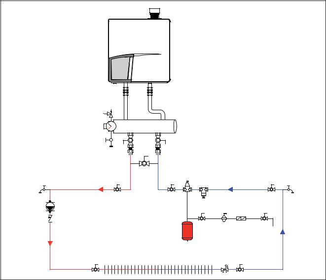
P |
Low Loss Header |
|
|
|
|
|
|
|
|
T |
|
|
|
|
|
V1 |
V2 |
|
|
Service valve |
Service valve |
|
|
|
|
11 |
7 |
|
|
|
1 |
6 |
5 |
|
2 |
|
|
8 |
9 |
3 |
|
|
|
|
|
|
10 |
|
|
|
|
|
4 |
|
Boiler basic piping |
|
|
|
figure 7 |
1.shut off valve
2.system circulator
3.check valve
4.balancing valve
5.boiler drain valve
6.dirt trap
7.air separator
8.automatic fill valve
9.back flow preventer
10.expansion tank
11.bypass for system cleaning
Installation & Servicing Instructions Rinnai Q-Series
19
6.1.1Plumbing Kit installation
i
i
i
NOTICE
NOTICE
NOTICE
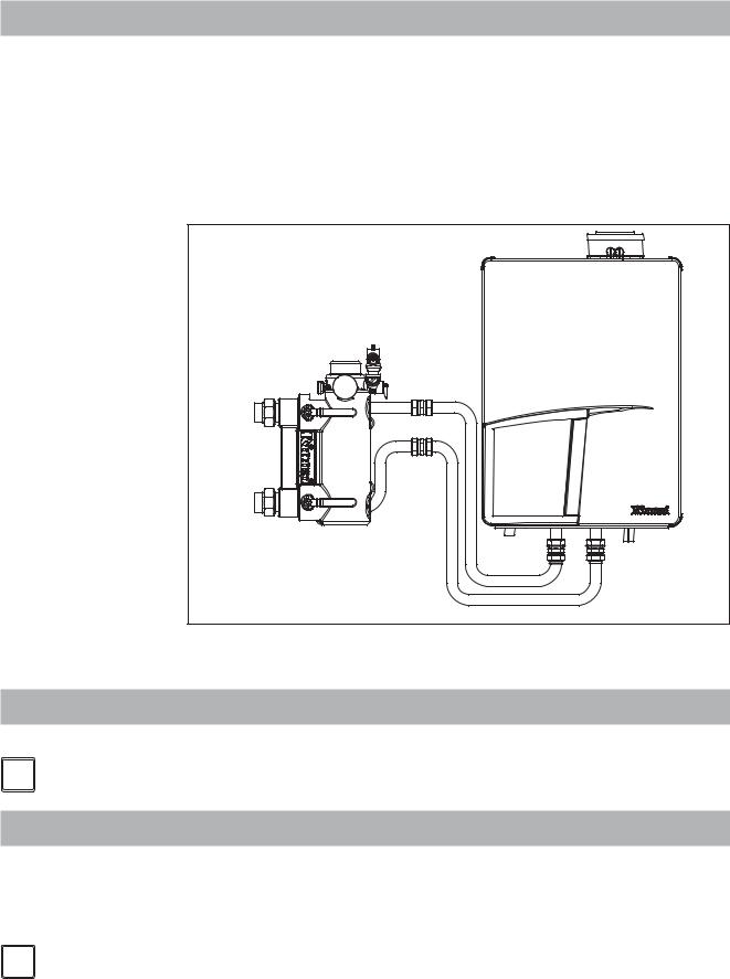
Rinnai supplies specific Plumbing Kits with each boiler type, which must be fitted directly underneath the boiler on the supply and return pipe. Find in chapter 5.3 the dimensions. Use of the Rinnai boiler without the plumbing kit will void the warranty.
To protect the entire heating system we recommend installing a dirt particle trap in the return circuit. When the boiler is installed to an existing heating system this trap is required. Use of a Y strainer is not permitted as a substitute for a dirt trap.
-Install shut-off valves immediately before and after the dirt particle filter to allow the trap to be cleaned.
-Position 3 (figure 8) is a garden hose thread boiler drain that can be used to drain the boiler or add water treatment additives to the system such as inhibitors or glycol.
-Position 4 (figure 8) is the supply connection for an indirect tank when used with the optional 3-way valve kit.
-For information on locating the expansion tank and system fill, please see the Rinnai Boiler Applications Manual.
Thoroughly flush all pipes and radiators. We recommend the use of a Rinnai approved system cleaner. Please refer to the list of approved Rinnai system cleaners in this chapter.
-Refer to the installation template and chapter 5.3 for the pipe connection dimensions.
The plumbing kit is not intended to support the weight of the piping. Appropriate piping supports should be used to support all attached piping to the boiler and plumbing kit.
Installation & Servicing Instructions Rinnai Q-Series
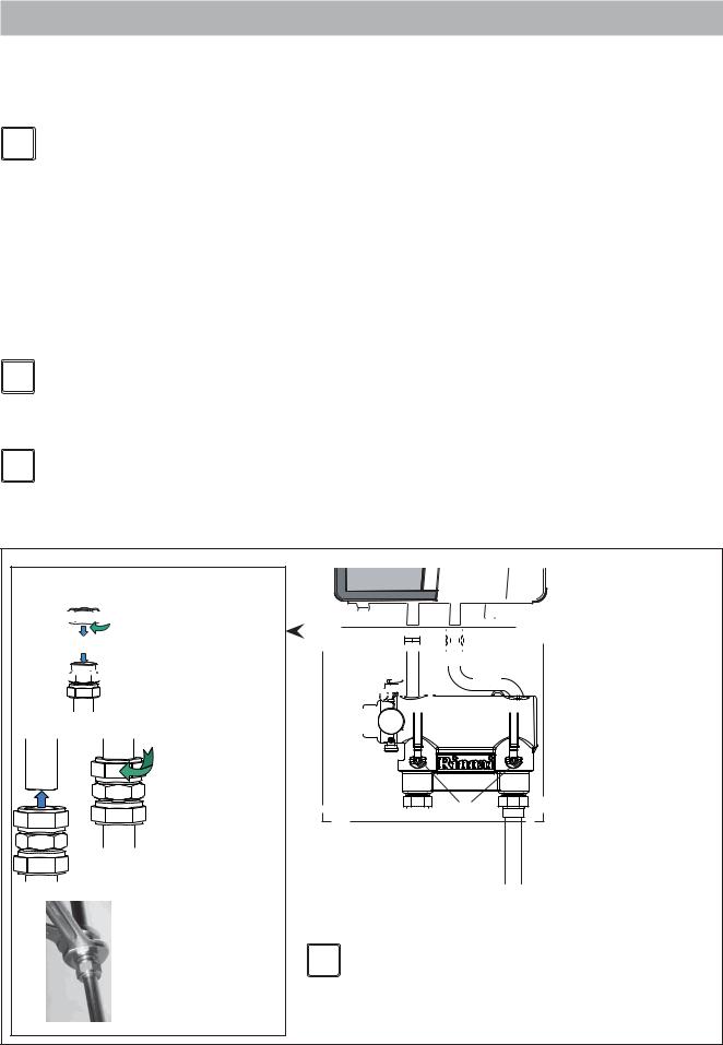
Compression fittings.
Parts:


 1. Nut

 2. Ferrule


 3. Fitting
Fitting instructions: |
|
|
1 |
2 |
1. Push the complete |
fitting over the pipe as |
||
|
|
far as possible. Ferrule |
|
|
should be over the |
|
|
pipe completely. |
|
|
2. Turn the nut handtight |
|
|
clockwise. |
3
3. Use 2 wrenches, one to hold the fitting on its place, the other for tighten the nut clockwise in 3/4 turn.
|
|
|
|
|
|
|
|
|
|
|
5 |
|
|
|
|
|
|
|
|
|
|
|
|
|
|
|
|
|
|
|
|
|
|
|
|
|
|
|
|
|
|
|
|
|
|
|
|
|
|
|
|
|
|
|
|
|
|
|
|
|
|
|
|
|
|
|
|
|
|
|
|
|
|
|
|
|
|
|
|
|
|
|
|
|
|
|
|
|
|
|
|
|
|
|
|
|
1 |
|
|
|
|
|
|
|
|
|
|
|
|
|
|
|
|
|
|
|
|||
|
|
|
|
|
|
|
|
|
|
|
|
|
|
|
|
|
|
|
|
||||
|
|
|
|
|
|
|
|
|
|
|
|
|
|
|
|
|
|
||||||
|
|
|
|
|
|
|
|
|
|
|
|
|
|
|
|
|
|
|
|
|
|||
|
|
|
|
|
|
|
|
|
|
|
|
|
|
|
|
|
|
|
|
|
|
|
|
|
|
|
|
|
|
|
|
|
|
|
|
|
|
|
|
|
|
|
|
|
|
|
|
2 


4 
 9
9


3
6
|
|
|
|
|
7 |
|
8 |
||
|
||||
1.Plumbing kit
2.Safety valve
3.Drain and Purge connection
4.DHW flow connection in case of optional internal 3 way valve
5.Bronze adapter fittings
6.Service valves*
7.Flow
8.Return
9.Pressure gauge*
* After installation of the plumbing kit to i NOTICE the boiler the pressure gauge and both
handles of the service valves must be mounted. Be sure the gauge is fitted leak free and that the handles are secured with the supplied nuts.
Plumbing Kit installation |
figure 8 |
20
-Boiler system flushing (Not Boiler heat exchanger)
When replacing an existing boiler the heating system should be flushed with the old boiler in place before the new boiler is added to the system. If the old boiler has already been removed a bypass must be piped in when the new boiler is installed in order to facilitate the flushing of the system.
The boiler must be valved off from the system, while the system is flushed. No system cleaner should ever enter the boiler heat exchanger due to its caustic nature which could damage the heat exchanger.
1.Close the shutoff valves on both the supply and return connections on the plumbing kit (V1 and V2).
2.Open the bypass valve (V4).
3.Connect pump outlet hose (H1) to the supply side purge station (BD1)
4.Connect drain hose (H3) to the return side purge station (BD2).
5.Pour the system cleaner into a pail and follow the system cleaner instructions on circulation time and volume to be added to the system.
6.Operate the charging pump (CP) and charge the system with the required volume of system cleaner
7.Close the supply side purge station (BD1)
8.Turn on the system pump(s) (SP) and circulate the cleaner through the system for required time as established by the cleaner manufacturer.
9.Once the time required by the system cleaner manufacturer has been met place the drain hose (H3) in a drain.
10.Turn off the system pump(s) (SP)
11.Close the main valve on the system return (V3) and open the return side purge station (BD2).
12.Open the auto feed on the system (F1) and allow water to rinse the system for whichever is greater; 10 minutes or the required rinse time by the system cleaner manufacturer.
P
Low Loss Header
T
V1 |
V2 |
V4
|
BD1 |
|
H1 |
CP |
SP |
|
|
|
H2 |
System cleaner
Boiler system flushing
V3 |
BD2 |
F1 |
H3 |
|
|
|
Drain |
figure 9
Installation & Servicing Instructions Rinnai Q-Series
21

Installation & Servicing Instructions Rinnai Q-Series
13.If the installation is a zone system be sure to purge out each zone individually
14.Close the auto feed on the system (F1)
15.Close the return side purge station (BD2) and disconnect the hose (H3).
16.Open the main valve on the system return (V3)
17.Close the bypass valve below the plumbing kit (V4).
18.Open shutoff valves on both the supply and return connections on the plumbing kit (V1 and V2).
19.Clean out the dirt trap
20.Test the pH of the water that will be used for filling the system
21.Test the water hardness of the water that will be used for filling the system
22.Use the proper water treatment to ensure the pH and water hardness are within the Rinnai boiler water quality guidelines
23.The boiler and system may now be filled
|
The following is a list of approved system cleaners, inhibitors, and antifreeze. |
|
|
Approved antifreeze: |
|
|
• Rhomar RhoGard Mutli-Metal (AL safe) |
• Sentinel X500 |
|
• Noble Noburst AL |
• Fernox Alphi 11 |
|
Approved system cleaner: |
|
|
• Noble Noburst Hydronic System Cleaner |
• Fernox F3 Cleaner |
|
- Rhomar Hydro-Solv 9100 |
• Sentinel X400 |
i NOTICE |
The system cleaners from NoBurst, Rhomar, and Fernox are NOT to be used in |
|
the boiler. The boiler must be closed off (valved off) from the rest of the system |
||
|
or not connected while the cleaners are in the system. The system should then |
|
|
be drained and then thoroughly flushed with clean water to remove all the |
|
|
system cleaner. |
|
|
Approved inhibitors: |
|
|
- Rhomar Pro-tek 922 |
• Sentinel X100 |
|
- Noble Noburst AL inhibitor |
|
|
|
|
- Connect the expansion tank to the system. See chapter 6.2. - Connect the pipes so that they are free from strain.
Connecting boiler with DHW tank
-Connect the external DHW tank according to the installation instructions of the DHW tank and fittings concerned. See chapter 7 and the Rinnai Boiler Applications Manual for additional information.
The boiler has a self-adjusting and self-protecting control system for the load and the pump capacity. By this means, the temperature difference between the supply and return water is checked.
22
Water filter |
figure 10 |
|
i |
NOTICE |
|
If the installation resistance is over the stated value; the pump will rotate at maximum capacity and the load will be adjusted until an acceptable temperature difference between supply and return water has been obtained. If, after this, the temperature difference is still not acceptable then the boiler will switch off and wait until an acceptable temperature has arisen.
If an unacceptable temperature is detected, the control will repeatedly try to achieve water flow over the boiler. If not the boiler will switch off.
The electrical side of the external circulation pump (fig. 6, pos. 2) can be connected to the Control Tower. This pump thus switches simultaneously to the boiler pump. The maximum absorbed current consumption of the external circulation pump may not exceed 120V, 2 Amp. If a pump with a larger current draw is required an isolation relay must be used. See the Rinnai Boiler applications manual for further information. The extra external pump must be selected according to the installation resistance
and required flow.
As standard the boiler is provided with a water filter in the return pipe of the boiler (fig. 10), so that debris from the central heating water is prevented from affecting the boiler.
The boiler is designed to be used on pressurized heating systems only (closed loop).
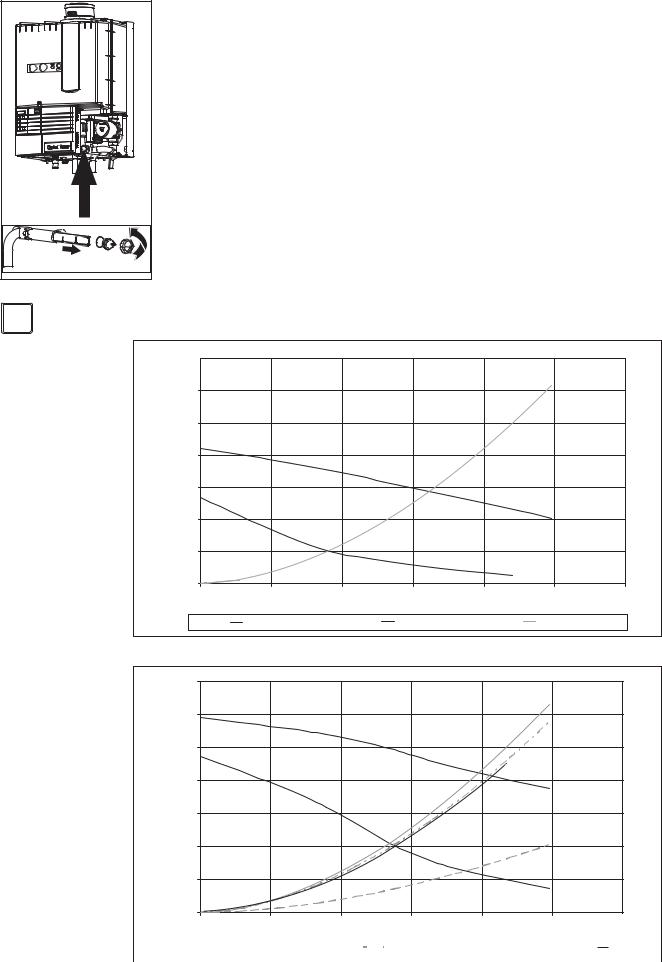
Q85S |
14 |
|
|
|
|
|
32.3 |
|
12 |
|
|
|
|
Q85S |
27.7 |
|
10 |
|
|
|
|
23.0 |
|
|
8 |
|
|
|
|
|
18.5ofhead |
|
PSI |
|
|
|
|
|
Feet |
|
6 |
|
|
|
|
|
13.8 |
|
4 |
|
|
|
|
|
9.2 |
|
2 |
|
|
|
|
|
4.6 |
|
0 |
|
|
|
|
|
0 |
|
0 |
2 |
4 |
6 |
8 |
10 |
12 |
|
|
|
|
Q [gallons/min] |
|
|
|
|
|
UPER 20-58 |
25% |
UPER 20-58 |
100% |
Resistance Q85S |
|
pump index lines UPER 20-58 |
|
|
|
|
graph 1a |
||
Q130S 14 |
|
|
|
|
|
32.3 |
|
Q175S |
|
|
|
|
|
|
|
Q175C 12 |
|
|
|
Q175S |
|
27.7 |
|
Q205S |
|
|
|
|
|
|
|
|
|
|
|
|
|
|
|
10 |
|
|
|
Q175C |
|
23.0 |
|
|
8 |
|
|
|
Q130S |
|
head |
|
|
|
|
|
18.5 |
||
PSI |
|
|
|
|
|
|
Feetof |
|
6 |
|
|
|
|
|
13.8 |
|
4 |
|
|
|
|
|
9.2 |
|
|
|
|
|
Q205S |
|
|
|
2 |
|
|
|
|
|
4.6 |
|
0 |
|
|
|
|
|
0 |
|
0 |
2 |
4 |
6 |
8 |
10 |
12 |
|
|
|
|
Q [gallons/min] |
|
|
|
|
|
|
UPER 20-78 |
|
UPER 20-78 |
|
Restistance |
|
Resistance |
|
|
|
Resistance |
Resistance |
|
|
|
|
|
|
|
|
|
||||||||
|
25% |
|
100% |
|
Q175S |
|
Q175C |
|
|
|
Q205S |
Q130S |
|
||
|
|
|
|
|
|
|
|
|
|
|
|
||||
pump index lines UPER 20-78 |
|
|
|
|
|
|
|
|
|
graph 1b |
|
||||
Installation & Servicing Instructions Rinnai Q-Series
23
Installation & Servicing Instructions Rinnai Q-Series
6.1.2Side mounting kit for the Low Loss header
A side mounting kit for the low loss header is available as an accessory. This kit relocates the low loss header from directly below the boiler to the left side of the boiler only. The kit includes all the parts required to relocate the low loss header including all mounting brackets and material. This kit provides an alternative to for installations with height limitations and allows for an alternative piping installation.
Kit 2 for boiler models Q85S and Q130S Rinnai part number: 804000072
Kit 3 for boiler models Q175S, Q175C, and Q205S Rinnai part number: 804000073.
Side mounting kit |
figure 11 |
6.1.3Safety valve
i NOTICE |
An ASME 30 psi pressure relief valve is installed on the plumbing kit included |
with the boiler. |
6.1.4Low water cut off
The Rinnai Q boiler has a factory installed pressure switch type Low Water Cut Off (LWCO). Check your local codes to see if a Low Water Cut Off is required (LWCO) and if this device conforms to local code. See the Rinnai Boiler Applications Manual for further information.
i NOTICE |
The Low water cut off is not serviceable. |
24

6.2Boiler expansion tank
i i
i
i
|
An expansion tank must be part of the central heating system. The expansion tank |
|
must be appropriate to the water content of the installation. The pre-charge pressure |
|
depends on the installation height above the mounted expansion tank. The expansion |
|
tank is NOT a part of the delivery and should be sourced locally. Please refer to the |
|
expansion tank manufacturer for further information. The Combi boiler Q175C is |
|
equipped with an expansion tank connection. This pipe is connected with the three |
|
way valve and boiler pump. |
NOTICE |
Fill expansion tank to a minimum of 14.5 psi. |
|
|
|
For the boiler to function correctly, it is necessary to connect the expansion |
NOTICE |
tank to the expansion tank connection on the boiler. If the expansion tank is not |
|
connected to the supplied connection damage to the boiler may occur. |
|
Note: |
|
The solo boilers Q85S, Q130S, Q175S and Q205S can be provided with an optional |
|
internal three way valve. When this valve is installed in the boiler, the boiler is provided |
|
with an expansion tank connection. This pipe is connected with the three way valve |
|
and boiler pump. |
NOTICE |
For the boiler to function correctly, it is necessary to connect the expansion |
tank to the expansion tank connection on the boiler. If the expansion tank is not |
|
|
connected to the supplied connection damage to the boiler may occur. |
|
See the Rinnai Boiler Applications Manual for further information regarding placement |
|
of the expansion tank in the system. See the Rinnai 3-way valve indirect tank |
|
installation manual for further information regarding the installation of the 3-way valve |
|
indirect tank kit. |
NOTICE |
The boiler cannot be used with an open type expansion tank. |
6.3Underfloor heating system (plastic pipes)
|
When using oxygen-permeable pipes, e. g. for floor heating systems, you must |
|
separate the system using plate heat exchangers. |
i NOTICE |
No recourse can be made to the terms of the limited warranty in the event of |
failure to observe the regulations pertaining to plastic underfloor heating pipes. |
Installation & Servicing Instructions Rinnai Q-Series
25
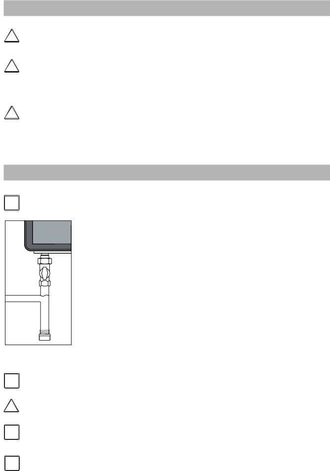
Installation & Servicing Instructions Rinnai Q-Series
6.4Gas connection
!
!
!
DANGER
WARNING
DANGER
Only work on gas lines if you are licensed for such work.
If these instructions are not followed exactly, a fire or explosion may result causing property damage, personal injury or death.
Rinnai wall mounted boilers are built to run on Natural Gas or Propane Gas. The gas type the boiler is suitable for is indicated on the packaging and on the boiler by a blue label with Natural Gas or a green label with Propane Gas and on the identification plate on the boiler.
First check the identification plate on the boiler for the suitable gas type.
Do not use the boiler for another type of gas than indicated on the identification plate of the boiler. This will cause improper functioning and can damage the boiler.
Natural gas: |
refer to chapter 6.4.1 |
Propane gas: |
refer to chapter 6.4.2 |
6.4.1.Gas connection with natural gas
i NOTICE
Sediment trap |
figure 12a |
The gas supply connection must comply with local regulations or, if such regulations do not exist, with the National Fuel Gas Code, ANSI Z 223.1.
For Canada, the gas connection must comply with local regulations or, if such regulations do not exist, with the CAN/CSA B149.1, Natural Gas and Propane Installation Code.
Pipe sizing for natural gas
Contact gas supplier to size the gas supply line and meter.
Gas piping
A sediment trap must be installed upstream of the gas controls.
The boiler gas pipe is equipped with external 3/4" M-NPT thread, onto which the tail piece of the gas shut off valve can be connected. Use appropriate sealing.
The connection to the boiler must include a suitable method of disconnection and a gas control valve must be installed adjacent to the boiler for isolation purposes. The nominal inlet working gas pressure measured at the boiler should be 7" W.C. (18 mbar) for Natural gas (Gas A). Maximum pressure with no flow (lockup) or with the boiler running is 10.5" W.C. Minimum pressure with the gas flowing (verify during boiler startup) is 4.0" W.C.
i
!
i
i
NOTICE
DANGER
NOTICE
NOTICE
The gas pipe must be fitted to the gas valve free from any strain.
Make sure that the gas pipe system does not contain dirt, particularly with new pipes.
Always check the safety of the gas pipe system by means of a bubble test using leak-search spray.
The boiler and its individual shut off valve must be disconnected from the gas supply piping system during any pressure testing of that system at test pressures in excess of 1/2 PSI (3.5kPa).
The boiler must be isolated from the gas supply piping system by closing its individual manual shutoff valve during any pressure testing of the gas supply piping system at test pressures equal to or less than 1/2 PSI (3.5 kPa).
26
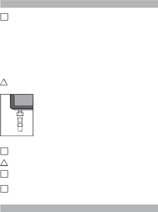
6.4.2
i NOTICE
!DANGER
Gas connection with propane gas
The gas supply connection must comply with local regulations or, if such regulations do not exist, with the National Fuel Gas Code, ANSI Z 223.1.
For Canada, the gas connection must comply with local regulations or, if such regulations do not exist, with the CAN/CSA B149.1, Natural Gas and Propane Installation Code.
Pipe sizing for propane gas
-Contact gas supplier to size pipes, tanks, and 100% lockup gas pressure regulator.
Propane Supply Pressure Requirements
-Adjust propane supply regulator provided by the gas supplier for 14 inches W.C. maximum pressure.
-Pressure required at gas valve inlet pressure port:
-Maximum 14" W.C. with no flow (lockup) or with boiler running.
-Minimum 8" W.C. with gas flowing (verify during boiler startup).
Ensure that the high gas pressure regulator is installed at least 6 to 10 feet upstream of the boiler.
Gas piping
-Use a gas shut off valve compatible with propane gas.
-A sediment trap must be provided upstream of the gas controls.
The boiler pipe is provided with external 3/4" M-NPT thread, onto which the tail piece of the gas shut off valve can be screwed. Use appropriate sealing.
The connection to the boiler must include a suitable method of disconnection. A gas control valve must be installed adjacent to the boiler for isolation purposes. The nominal inlet working gas pressure measured at the boiler should be 12 inch W.C. (30mbar) for Propane gas (Gas E).
The gas pipe must be fitted to the gas valve free from any strain.
Gas shut off valve onto boiler |
|
||
|
figure 12b |
Make sure that the gas pipe system does not contain dirt, particularly with new |
|
|
|
||
i |
NOTICE |
pipes. |
|
Always check the safety of the gas pipe system by means of a bubble test using |
|||
|
|
||
! |
DANGER |
leak-search spray. |
|
The boiler and its individual shut off valve must be disconnected from the |
|||
|
|
||
i |
NOTICE |
gas supply piping system during any pressure testing of that system at test |
|
pressures in excess of 1/2 PSI (3.5kPa). |
|||
|
|
The boiler must be isolated from the gas supply piping system by closing its |
|
i |
NOTICE |
individual manual shutoff valve during any pressure testing of the gas supply |
|
piping system at test pressures equal to or less than 1/2 PSI (3.5 kPa). |
|||
6.5Hot water supply (Combi boiler Q175CN/Q175CP)
Connection of the drinking water installation should be performed according to the national secondary drinking water regulations.
Installation & Servicing Instructions Rinnai Q-Series
27
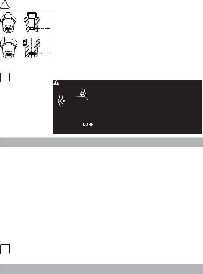
Installation & Servicing Instructions Rinnai Q-Series
! |
DANGER |
Do NOT use toxic chemicals, such as those used for boiler treatment in potable |
||
water heating systems used for space heating. |
||||
|
|
The sanitary water pipes can be connected to the installation by use of adapter |
||
|
|
fittings. The cold water inlet on the Combi boilers must be equipped with the following |
||
|
|
components (counted in the water flow direction):Flow regulator valve (supplied), |
||
|
|
Safety group, Expansion vessel 87 PSI / 6bar (potable water, blue). |
||
|
|
A flow regulator valve is supplied with the boiler. The flow regulator valve ensures that |
||
|
|
a quantity of water is supplied which has a outlet temperature of 120°F (assuming a |
||
|
|
cold water temperature of 45°F). The quantity of water is virtually unaffected by the |
||
|
|
water pressure. The 3/4" NPT adapter fitting with the flow reducing valve must be |
||
|
|
fitted in the cold water connection (see Dimensions 5.3, cold water pipe -k). |
||
flow regulator valve |
figure 13 When there is a water pressure lower than 22PSI / 1.5 bar it is advisable to |
|||
|
|
remove the inside mechanism of the flow reducing valve. Contact Rinnai for |
||
i |
NOTICE |
removal instructions. |
|
|
DANGER |
Hot water can be dangerous, especially for infants or children, the elderly, |
|||
|
|
|||
|
|
or infirm. There is hot water scald potential if the thermostat is set too high. |
||
|
|
|
Water temperatures over 125º F (51º C) can cause severe burns or |
|
|
|
|
scalding resulting in death. |
|
|
|
|
Hot water can cause first degree burns with exposure for as little as: |
|
3 seconds at 140º F (60º C)
20 seconds at 130º F (54º C)
8 minutes at 120º F (48º C)
Test the temperature of the water before placing a child in the bath or shower.
Do not leave a child or an infirm person in the bath unsupervised.
6.5.1Domestic Water quality
|
Appropriate steps must be taken to ensure the indirect tank water heater does not |
|
become plugged by scale caused by hard water or sediment. If the indirect tank water |
|
heater becomes plugged by either scaling from hard water or sediment it is not the |
|
responsibility of Rinnai. |
|
1. Water hardness for DHW |
|
When there is a water hardness of more than 6 to 7 grains hardness for domestic |
|
water, a water softener must be installed on the inlet side of the DHW connection. |
|
2. Sediment in DHW |
|
If there is sediment in your domestic water supply a sediment filter or other suitable |
|
device should be used to remove it before the water enters the indirect tank water |
|
heater. |
|
3. Water Chemistry for DHW |
|
The water used for domestic must have a water pH between 6.0 and 8.0, contain less |
|
than 1.7 gpg (20 mg/l) of Sodium, and a concentration of Chlorine less than 5.8 gpg |
|
(100 mg/L). |
i NOTICE |
If problems occur when using sanitary water outside of the above stated |
|
requirements, no recourse can be made to the terms of the limited warranty. |
6.5.2Domestic water treatment Accessory
Rinnai offers a domestic water treatment device that can help reduce scale build up. This device can be installed on the incoming cold water line for any combi boiler. For additional information on contact Rinnai.
28
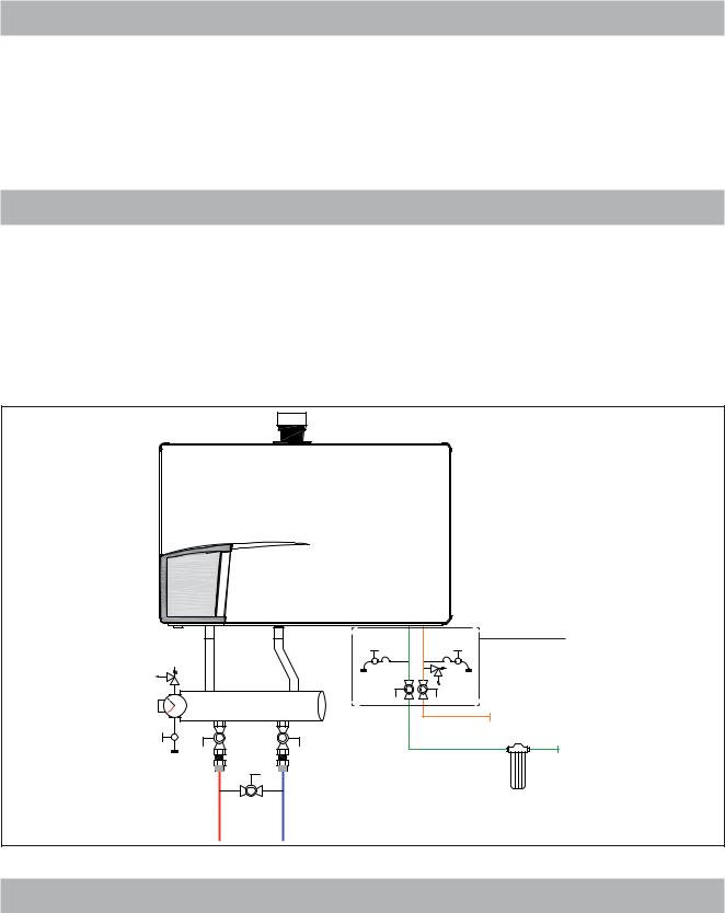
6.5.3DHW Expansion Tank
A domestic water expansion tank could be required by local code. Check local code to determine if it is required.
If a combi boiler is installed in a closed water supply system, such as one having a backflow preventer in the cold water supply line, means shall be provided to control thermal expansion. Contact the water supplier or local plumbing inspector on how to control thermal expansion.
6.5.4Installing a valve kit
A means to isolate the domestic indirect tank water heater for cleaning must be provided at installation. Refer to figure 13 for proper piping layout. A Rinnai valve kit can be used on domestic water connections for all combi boilers to allow for cleaning of indirect tank water heater and installation the domestic hot water pressure relief valve.
•Rinnai recommends the use of the WRIK-LF-F(3/4” NPT thread connection) or WRIK-C kit (WRIK-C (3/4” sweat connection) when connecting the domestic water lines to the boiler.
•Use of this kit will assist in flushing the indirect tank water heater in areas where water quality issues exist, as well as improve overall product serviceability.
Plumbing valve Kit |
P |
Low Loss Header |
|
|
|
|
|
|
T |
|
|
|
|
|
|
Sediment Filter |
|
V1 |
V2 |
Cold water |
|
|
||
Service valve |
Service valve |
|
|
Boiler DHW piping |
figure 14 |
6.5.5Pressure relief Valve for Combi boilers
-An approved pressure relief valve is required by Rinnai for all water heating systems.
-The relief valve must comply with the standard for Relief Valves andAutomatic Gas Shutoff Devices for Hot Water Supply Systems ANSI Z21.22 and/or the standard Temperature, Pressure, Temperature and Pressure Relief Valves and Vacuum Relief Valves, CAN1-4.4.
-The relief valve must be rated up to 150 psi and to at least the maximum BTU/hr of the appliance.
Installation & Servicing Instructions Rinnai Q-Series
29

Installation & Servicing Instructions Rinnai Q-Series
-The discharge from the pressure relief valve should be piped to the ground or into a drain system to prevent exposure or possible burn hazards to humans or other plant or animal life. Follow local codes. Water discharged from the relief valve could cause severe burns instantly, scalds, or death.
-The pressure relief valve must be manually operated once a year to check for correct operation.
-The relief valve should be added to the hot water outlet line according to the manufacturer instructions. DO NOT place any other type valve or shut off device between the relief valve and the combi boiler.
-Do not plug the relief valve and do not install any reducing fittings or other restrictions in the relief line. The relief line should allow for complete drainage of the valve and the line.
-If a relief valve discharges periodically, this may be due to thermal expansion in a closed water supply system. Contact the water supplier or local plumbing inspector on how to correct this situation. Do not plug the relief valve.
-Rinnai does not require a combination temperature and pressure relief valve for this appliance. However local codes may require a combination temperature and pressure relief valve.
-If a combi boiler is installed in a closed water supply system, such as one having a backflow preventer in the cold water supply line, means shall be provided to control thermal expansion. Contact the water supplier or local plumbing inspector on how to control thermal expansion.
6.6Condensate drain pipe
This boiler produces condensate. Condensate must be drained otherwise the boiler will not function and can cause product or property damage.
The condensation drain pipe should be connected to a drain in the building by means of an open connection. By this means the possibility of drain gases effecting the boiler is prevented. The drain connection should have a minimum diameter of 1.3" / 32mm.
Install the condensation drain pipe according to applicable local code.
If the condensate outlet of the boiler is lower than the public sewage system a condensate pump must be used.
The condensate produced by the boiler has a pH value between 3 and 4.
Install a neutralization unit if required by local code. It is recommended, but not required to install a condensate neutralizer. Rinnai offers a condensate neutralizer designed to work with all boiler models. The condensate neutralizer kit comes with all the necessary fittings and mounting material. PVC pipe must be supplied by the installation contractor. Rinnai part number: 804000074
i i
NOTICE
NOTICE
Do not drain the condensation water to the external rain gutter because of the danger of freezing and blockage of the drain.
Before putting the boiler into operation fill the condensate trap with 1.27 cups / 300 ml of water. If the boiler will be installed in a high temperature installation such as baseboard with a supply temperature of 160°F or above, fill the condensate trap with mineral oil instead of water.
Use materials approved by the authority having jurisdiction. In absence of such i NOTICE authority, PVC and CPVC pipe must comply with ASTM D1785, F441 or D2665.
Cement and primer must comply with ASTM D2564 or F493.
For Canada, use CSA or ULC certified PVC or CPVC pipe, fittings and cement.
Periodic cleaning of the condensate disposal system must be carried out. i NOTICE See the Rinnai Boiler Applications Manual for further information and a piping
diagram for the condensate.
30
 Loading...