


INSTALLATION AND OPERATION MANUAL
M-Series Condensing Boiler
Wall-Mounted, Gas-Fired Combi Boiler
Central Heating and Domestic Hot Water
MODELS
M060C
M090C
M120C
M160C
Certified to ANSI Z21.13 and CSA 4.9
WARNING If the information in these instructions are not followed exactly, a fire or explosion may result causing property damage, personal injury, or loss of
life.
•Do not store or use gasoline or other flammable vapors and liquids in the vicinity of this or any other appliance.
•WHAT TO DO IF YOU SMELL GAS
−Do not try to light any appliance.
−Do not touch any electrical switch; do not use any phone in your building.
−Immediately call your gas supplier from a neighbor’s phone. Follow the gas supplier’s instructions.
−If you cannot reach your gas supplier, call the fire department.
•Installation and service must be performed by a qualified installer, service agency or the gas supplier.
READ AND SAVE THIS MANUAL
Rinnai M-Series Condensing Boiler Combi Manual

1. Welcome........................................................................................................................... |
4 |
|
2. Safety................................................................................................................................ |
5 |
|
2.1 |
Safety Symbols ........................................................................................................................... |
5 |
2.2 |
Safety Precautions...................................................................................................................... |
5 |
3. About the Boiler ................................................................................................................ |
7 |
|
3.1 |
Front View .................................................................................................................................. |
7 |
3.2 Bottom View............................................................................................................................... |
8 |
|
3.3 Components ............................................................................................................................... |
9 |
|
3.4 |
Specifications............................................................................................................................ |
10 |
3.5 Dimensions ............................................................................................................................... |
11 |
|
3.6 |
Accessories ............................................................................................................................... |
13 |
3.7 How to Remove the Front Panel .............................................................................................. |
14 |
|
4. Installation ...................................................................................................................... |
15 |
|
4.1 |
Installation Guidelines.............................................................................................................. |
15 |
4.2 What You’ll Need...................................................................................................................... |
16 |
|
4.3 |
Items Included.......................................................................................................................... |
17 |
4.4 |
Choose an Installation Location ............................................................................................... |
18 |
4.5 Mount the Boiler to the Wall ................................................................................................... |
20 |
|
5. Venting ........................................................................................................................... |
21 |
|
5.1 |
Guidelines................................................................................................................................. |
21 |
5.2 |
Venting Installation Sequence.................................................................................................. |
22 |
5.3 Termination Considerations..................................................................................................... |
22 |
|
5.4 |
Venting Options........................................................................................................................ |
23 |
6. Gas Supply ...................................................................................................................... |
43 |
|
6.1 Connect the Gas Supply............................................................................................................ |
43 |
|
6.2 |
Gas Operating Instructions....................................................................................................... |
45 |
6.3 |
Gas Pipe Sizing Reference Tables ............................................................................................. |
46 |
7. DHW System Piping ......................................................................................................... |
48 |
|
7.1 |
Guidelines................................................................................................................................. |
48 |
7.2 |
Instructions............................................................................................................................... |
48 |
7.3 Piping Diagram for a Basic DHW Installation............................................................................ |
49 |
|
8. CH System Piping............................................................................................................. |
50 |
|
8.1 |
Guidelines................................................................................................................................. |
50 |
8.2 |
Instructions............................................................................................................................... |
50 |
8.3 Common CH Components ........................................................................................................ |
51 |
|
8.4 Piping Diagram for a Basic CH System (With Hydraulic Separation)........................................ |
53 |
|
8.5 |
Hydraulic Separation ................................................................................................................ |
54 |
8.6 Connect the Pressure Relief Valves (DHW and CH).................................................................. |
55 |
|
2 |
Rinnai M-Series Condensing Boiler Combi Manual |
8.7 Connect the Condensate Drain Line......................................................................................... |
56 |
|
9. Power Supply .................................................................................................................. |
58 |
|
9.1 Guidelines................................................................................................................................. |
58 |
|
9.2 Electrical Connections .............................................................................................................. |
59 |
|
9.3 Post-Power Supply Connection Checklist................................................................................. |
59 |
|
10. Commissioning .............................................................................................................. |
60 |
|
10.1 Safety Precautions.................................................................................................................. |
60 |
|
10.2 |
Instructions............................................................................................................................. |
60 |
10.3 Air Purge Process.................................................................................................................... |
63 |
|
11. Post-Installation Checklist ............................................................................................. |
64 |
|
12. Operation...................................................................................................................... |
66 |
|
12.1 Start-Up Information.............................................................................................................. |
66 |
|
12.2 Control Panel.......................................................................................................................... |
67 |
|
12.3 |
Basic Operation Settings......................................................................................................... |
70 |
12.4 Parameter Settings ................................................................................................................. |
75 |
|
12.5 Outdoor Reset Control ........................................................................................................... |
80 |
|
12.6 Diagnostic Codes .................................................................................................................... |
86 |
|
12.7 Forced Hi/Low Fire Modes ..................................................................................................... |
87 |
|
12.8 Freeze Protection ................................................................................................................... |
88 |
|
13. Maintenance ................................................................................................................. |
89 |
|
13.1 Owner Maintenance............................................................................................................... |
89 |
|
13.2 Licensed Professional Maintenance....................................................................................... |
90 |
|
13.3 |
Test the Ignition Safety Shut Off Device................................................................................. |
92 |
14. Appendices.................................................................................................................... |
93 |
|
14.1 |
Approved Cleaners, Inhibitors and Antifreezes..................................................................... |
93 |
14.2 |
Flush the CH Plumbing System.............................................................................................. |
94 |
14.3 |
Boiler Parts ............................................................................................................................ |
95 |
14.4 |
System Application Examples.............................................................................................. |
103 |
14.5 Gas Conversion..................................................................................................................... |
109 |
|
14.6 Wiring Diagram..................................................................................................................... |
113 |
|
14.7 Ladder Diagram .................................................................................................................... |
114 |
|
14.8 |
CH Pressure Drop and Flow Curve....................................................................................... |
115 |
14.9 |
DHW Pressure Drop and Flow Curve................................................................................... |
116 |
14.10 Resistance/Temperature Table for Sensors ....................................................................... |
117 |
|
14.11 Remove a Boiler from a Common Vent System ................................................................. |
118 |
|
14.12 Massachusetts State Gas Regulations ................................................................................ |
119 |
|
14.13 Warranty ............................................................................................................................ |
120 |
|
Rinnai M-Series Condensing Boiler Combi Manual |
3 |
1
Thank you for purchasing a Rinnai Condensing Boiler. Before installing and operating this boiler, be sure to read these instructions completely and carefully to familiarize yourself with the boiler’s features and functionality.
•You must read the entire manual to properly operate the boiler.
•Keep this manual for future reference.
•As when using any appliance generating heat, there are certain safety precautions you should follow. See section “2.2 Safety Precautions” for detailed safety precautions.
•Be sure your boiler is installed by a licensed installer.
•If installing in the state of Massachusetts, read section “14.12 Massachusetts State Gas Regulations” in this manual.
Following is a list of common acronyms and abbreviations used in this manual:
ANSI |
American National Standards |
|
Institute |
||
|
||
Btu |
British Thermal Unit |
|
CH |
Central Heating |
|
DHW |
Domestic Hot Water |
|
GPM |
Gallons per minute |
|
LP |
Liquid Propane |
|
LWCO |
Low Water Cut Off |
|
NG |
Natural Gas |
|
PP |
Polypropylene |
|
PRV |
Pressure Relief Valve |
|
PSI |
Pounds per square inch |
|
W.C. |
Inches water column |
|
|
|
•A trained and qualified professional must install the boiler, inspect it, and leak test it before use. The warranty will be voided due to any improper installation.
•The trained and qualified professional should have skills such as:
−Gas line sizing
−Connecting gas lines, water lines, valves, and electricity
−Knowledge of applicable national, state, and local codes
−Installing venting through a wall or roof
−Training in installation of condensing boilers. Training on Rinnai M-Series Condensing Boilers is accessible at www.trainingevents.rinnai.us.
•Read all instructions in this manual before installing the boiler. The boiler must be installed according to the exact instructions in this manual.
•Proper installation is the responsibility of the installer.
•When installation is complete, leave this manual with the boiler or give the manual directly to the consumer.
For Your Records
Dealer Name:
Dealer Phone:
Purchase Date:
Serial #:
Located on left side of unit
4 |
Rinnai M-Series Condensing Boiler Combi Manual |
2
 WARNING
•If the information in these instructions is not followed exactly, a fire or explosion may result causing property damage, personal injury, or death.
•Do not store or use gasoline or other flammable vapors and liquids in the vicinity of this or any other appliance.
•WHAT TO DO IF YOU SMELL GAS:
−Do not try to light any appliance.
−Do not touch any electrical switch; do not use any phone in your building.
−Immediately call your gas supplier from a neighbor’s phone. Follow the gas supplier’s instructions.
−If you cannot reach your gas supplier, call the fire department.
•Installation and service must be performed by a qualified installer, service agency or the gas supplier.
•The warning signs in this manual are here to prevent injury to you and others. Please follow them explicitly.
This manual contains the following important safety symbols. Always read and obey all safety messages.
Safety alert symbol. Alerts you to potential hazards that can kill or hurt you and others.
 DANGER
Indicates an imminently hazardous situation which, if not avoided, will result in personal injury or death.
Rinnai M-Series Condensing Boiler Combi Manual
 WARNING
Indicates a potentially hazardous situation which, if not avoided, could result in personal injury or death.
 CAUTION
Indicates a potentially hazardous situation which, if not avoided, could result in minor or moderate injury. It may also be used to alert against unsafe practices.
The following precautions apply to the installer and consumer. Read and follow all instructions in this section.
•Before operating, smell all around the appliance area for gas. Be sure to smell next to the floor because some gas is heavier than air and will settle on the floor.
•Keep the area around the appliance clear and free from combustible materials, gasoline, and other flammable vapors and liquids.
•Do not store or use gasoline or other flammable vapors and liquids in the vicinity of this or any other appliance.
•Combustible construction refers to adjacent walls and ceiling and should not be confused with combustible or flammable products and materials. Combustible and/or flammable products and materials should never be stored in the vicinity of this or any gas appliance.
•Always check the water temperature before entering a shower or bath.
5

•Do not use this appliance if any part has been under water. Immediately call a licensed professional to inspect the appliance and replace any part of the control system and any manual gas control valve which has been under water.
•Do not use substitute materials. Use only parts certified for the appliance.
•Should overheating occur or the gas supply fail to shut off, turn off the manual gas control valve to the appliance.
•It is strongly recommended that you use a trained and qualified professional who has attended a Rinnai installation training class to adjust parameter settings.
•Do not use an extension cord or adapter plug with this appliance.
•Any alteration to the appliance or its controls can be dangerous and will void the warranty.
•To protect yourself from harm, before performing maintenance:
−Turn off the electrical power supply by unplugging the power cord or by turning off the electricity at the circuit breaker. (The boiler controller does not control the electrical power.)
−Turn off the gas at the gas control, usually located immediately below the boiler.
−Turn off the incoming water supply. This can be done at the isolation valve immediately below the boiler for the domestic hot water. Turning off the water for the central heating system is done at the boiler system filling station shut-off valve or the main water supply to the building.
−Use only your hand to turn the manual gas control valve. Never use tools. If the manual gas control valve will not turn by hand, do not try to repair it; call a trained and qualified professional. Force or attempted repair may result in a fire or explosion.
•Proper venting is required for the safe operation of this appliance. Failure to properly vent this appliance can result in death, personal injury and/or property damage.
•Flammable liquids such as cleaning solvents, aerosols, paint thinners, adhesives, gasoline and propane must be handled and stored with extreme care. These flammable liquids emit flammable vapors and when exposed to an ignition source can result in a fire hazard or explosion. Flammable liquids should not be used or stored in the vicinity of this or any other gas appliance.
•DO NOT operate the boiler without the front panel installed. The front panel should only be removed for service/ maintenance or replacing internal components.
•BURN HAZARD. Hot exhaust and vent may cause serious burns. Keep away from the boiler. Keep small children and animals away from the boiler.
•Heating supply, return and domestic hot water outlet pipes leaving the boiler can be hot to touch.
•Install the vent system per local and national codes.
•Do not install this boiler above 10,200 ft (3,109 m).
•Do not obstruct combustion air to the boiler.
•Rinnai recommends that every home have a carbon monoxide (CO) alarm in the hallway near bedrooms in each sleeping area. Check batteries monthly and replace them annually.
•California law requires the following Proposition 65 warning to be provided:
 WARNING
This product can expose you to chemicals including Nickel compounds, Lead and Lead compounds which are known to the State of California to cause cancer, birth defects or other reproductive harm. For more information, visit www.P65Warnings.ca.gov.
6 |
Rinnai M-Series Condensing Boiler Combi Manual |
3
Topics in this section
•Front View
•Bottom View
•Components
•Specifications
•Dimensions
•Accessories
•How To Remove the Front Panel
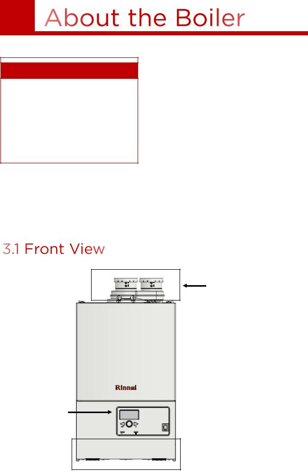
The M-Series Condensing Boiler is a wall-mounted, gas-fired boiler designed to providing heating and domestic hot water.
For complete boiler information, refer to the “Rinnai M-Series Condensing Boiler Installation Manual” supplied with the boiler, or visit rinnai.us.
Vent Connections
Controller
(front cover removed)
Piping Connections (visible
 below boiler)
Rinnai M-Series Condensing Boiler Combi Manual |
7 |
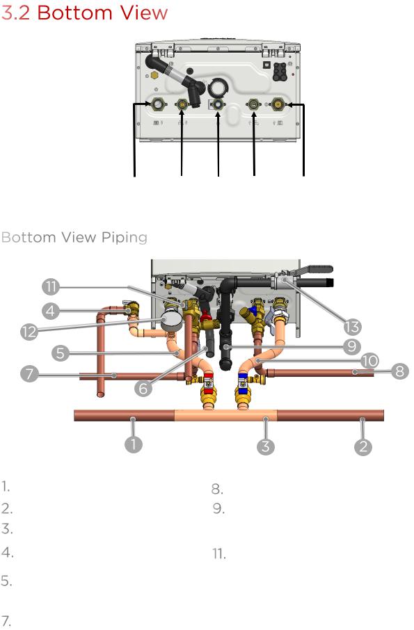
Central |
DHW |
Gas |
DHW |
Central |
Heating |
Hot Outlet |
|
Cold Inlet |
Heating |
Supply |
|
|
|
Return |
All items are field-supplied unless otherwise noted.
Supply to CH System
Return from CH System
Primary-Secondary Heating Kit
CH Pressure Relief Valve (supplied with boiler)
CH Supply
 Condensate Drain
Domestic Hot Water
Domestic Cold Water
Gas
 CH Return
Domestic Hot Water Pressure Relief Valve
 Central Heating Temperature Pressure
Gauge (supplied with boiler)
 Gas Shut Off Valve
8 |
Rinnai M-Series Condensing Boiler Combi Manual |

Exhaust Intake


Located behind #6 (Silencer)

|
Located |
|
behind |
|
#6 (Silencer) |

|
|
|
|
|
1 |
iCon Heat Exchanger |
|
2 |
Burner Hood with Burner Cassette |
|
|
|
|
3 |
Fan with Integrated Venturi |
|
4 |
Gas Valve |
|
5 |
Ignition Unit |
|
6 |
Silencer |
|
7 |
Condensate Tray |
|
8 |
Flue Gas Exhaust/Air Intake with |
|
Measuring Points |
||
|
9 |
Automatic De-aerator |
10 |
Control Panel |
|
|
11 |
Pressure Sensor |
12 |
Modulating Pump |
13 |
Plate Heat Exchanger |
|
|
14 |
Diverter Valve |
15 |
Flow Sensor |
16 |
Condensate Trap |
|
|
Rinnai M-Series Condensing Boiler Combi Manual |
9 |

Model |
|
|
M060C |
|
M090C |
M120C |
|
M160C |
Dimensions - w, h, d |
|
17 in. x 28 in. x 10 in. (439 mm x 699 mm x 264 mm) |
||||||
|
|
|
|
|
|
|
|
|
Weight |
|
|
77 lb (35 kg) |
|
|
83.6 lb (38 kg) |
|
|
Appliance Type |
|
|
Wall-Mounted, Gas-Fired Combi Boiler |
|||||
Installation Type |
|
|
|
Indoor |
|
|||
Ignition System |
|
|
|
|
Direct Electronic Ignition |
|
||
Heat Exchanger Type |
|
iCon1 |
|
|
iCon2 |
|
||
Heat Exchanger Surface Area |
|
7.3 sq ft |
|
|
11.8 sq ft |
|
||
|
Minimum |
|
NG: 17,000 |
|
|
NG: 23,500 |
|
|
Gas |
|
LP: 31,500 |
|
|
LP: 73,500 |
|
|
|
|
|
|
|
|
|
|||
Consumption |
Maximum (Central |
60,000 |
|
90,000 |
120,000 |
|
160,000 |
|
(Btu/h) |
Heating) |
|
|
|
||||
|
|
|
|
|
|
|
||
|
Maximum (DHW) |
|
103,000 |
|
|
160,000 |
|
|
Temperature |
Central Heating |
|
|
68° F - 185° F (20° C - 85° C) |
|
|||
(Min - Max) |
|
|
|
|||||
Setting |
|
|
|
|
|
|
|
|
DHW (Min - Max) |
|
104° F - 149° F (40° C - 65° C) |
|
|||||
|
|
|
||||||
|
|
|
|
|
1.4 |
1.4 |
|
1.4 |
|
|
|
1 Gallon |
|
Gallons |
|
||
|
Central Heating |
|
|
Gallons |
|
Gallons |
||
|
|
3.8 Liters |
|
5.2 Li- |
|
|||
Water |
|
|
|
5.2 Liters |
|
5.2 Liters |
||
|
|
|
|
ters |
|
|||
Content |
|
|
|
|
|
|
|
|
|
|
.05 Gallons |
|
.08 |
.08 |
|
.08 |
|
|
|
|
|
|
||||
|
DHW |
|
|
Gallons |
Gallons |
|
Gallons |
|
|
|
.2 Liters |
|
|
||||
|
|
|
|
.3 Liters |
.3 Liters |
|
.3 Liters |
|
|
|
|
|
|
|
|||
Water Supply |
Central Heating |
|
Minimum: 19 PSI |
Maximum: 45 PSI |
||||
DHW |
|
|
|
150 PSI (maximum) |
|
|||
Pressure |
|
|
|
|
||||
Pressure Relief Valve |
|
|
30 PSI |
|
||||
|
|
|
|
|||||
Pump Model |
|
|
|
|
Grundfos UPER 15-78 |
|
||
Sound Level |
|
|
46 dB |
|
|
54 dB |
|
|
|
Normal |
Central |
155 W |
|
177 W |
164 W |
|
191 W |
|
|
Heating |
|
|
||||
|
|
|
|
|
|
|
|
|
Electrical |
|
DHW |
185 W |
|
191 W |
191 W |
|
191 W |
Data |
Standby |
|
|
|
3.5 W |
|
||
|
Max Current |
|
|
|
1.97 Amps (maximum) |
|
||
|
Fuse |
|
|
|
5 Amps |
|
||
Gas |
Natural Gas |
|
|
|
3.0 in. - 10.5 in. W.C. |
|
||
Supply |
|
|
|
|
|
|
|
|
Propane |
|
|
|
8.0 in. - 13.5 in. W.C. |
|
|||
Pressure |
|
|
|
|
||||
Electric Connections |
|
|
|
AC 120 Volts, 60Hz. |
|
|||
Energy Star Qualified |
|
Recognized as the Most Efficient of ENERGY STAR® |
||||||
|
|
|
|
|
|
|
|
|
Certifications |
|
|
|
|
ANSI Z21.13, CSA 4.9 |
|
||
|
|
|
|
|
|
|
|
|
1Minimum flow may vary slightly depending on the temperature setting and the inlet water temperature. Minimum activation flow is 0.4 GPM (1.5 L/min).
2The maximum gas supply pressure must not exceed the value specified by the manufacturer. Rinnai products are continually being updated and improved; therefore, specifications are subject to change without prior notice.
10 |
Rinnai M-Series Condensing Boiler Combi Manual |
Measurements: in. (mm)
Vent Top Connections 3 in. (80 mm) PP, 3 in. PVC, 3/5 in. Concentric, 2 in. (60 mm) PP, 2 in. PVC
Rinnai M-Series Condensing Boiler Combi Manual |
11 |
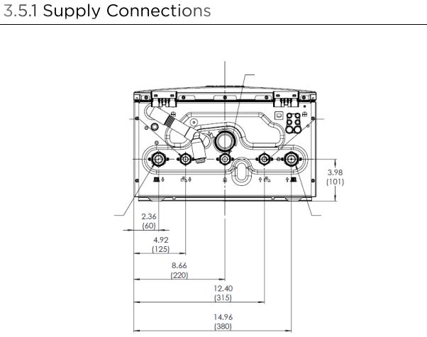
|
Gas |
|
Domestic Hot Water |
Domestic Cold |
|
|
|
|
Outlet |
|
Water Inlet |
|
|
|
Central Heating |
Central Heating |
Supply |
Return |
Connection |
Connection Size with Provided |
|
Adapters |
||
|
||
Gas |
3/4 in. NPT |
|
|
|
|
DWH In (Cold Inlet) |
3/4 in. NPT |
|
|
|
|
DHW Out (Hot Outlet) |
3/4 in. NPT |
|
|
|
|
CH In (CH Return) |
1 in. NPT |
|
|
|
|
CH Out (CH Supply) |
1 in. NPT |
|
|
|
12 |
Rinnai M-Series Condensing Boiler Combi Manual |
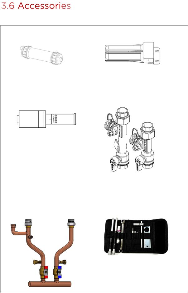
The following optional accessories are available for the Rinnai M-Series Condensing Boiler.
CONDENSATE NEUTRALIZER |
SCALECUTTER |
Neutralizes the condensate generated by the boiler.
SCALECUTTER REFILL CARTRIDGE
Refill cartridge for the ScaleCutter filter assembly.
PRIMARY SECONDARY HEATING KIT
PN: 803000023
Filters and reduces the amount of scale entering the boiler allowing for greater boiler longevity.
DHW ISOLATION VALVE KIT
For quick isolation of the boiler DHW connections.
BOILER TOOLKIT
PN: 809000024
Set of specific tools recommended for boiler service.
Rinnai M-Series Condensing Boiler Combi Manual |
13 |
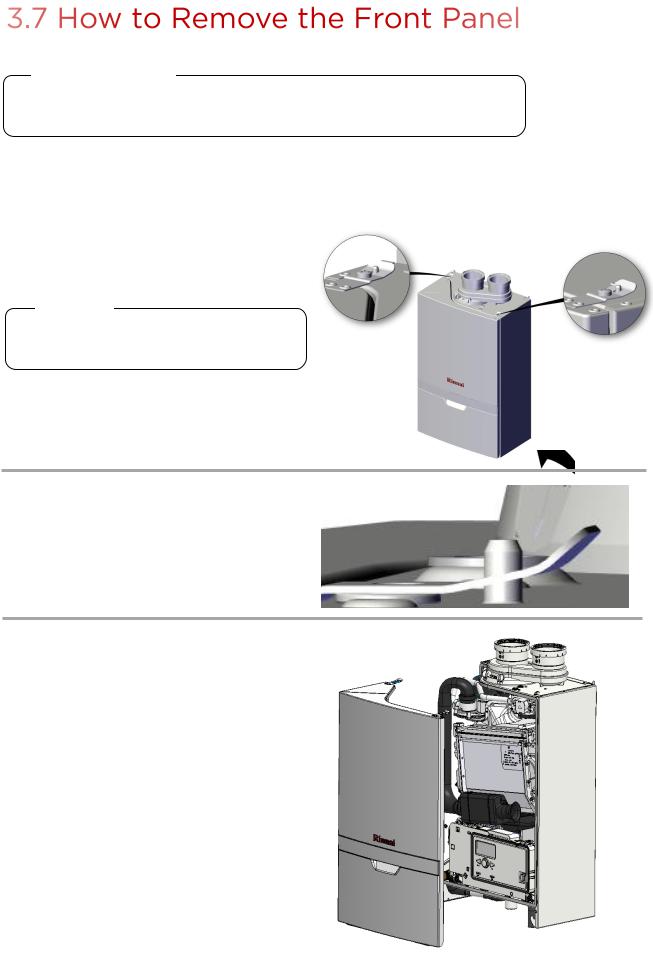
 IMPORTANT
Do not operate the boiler without the front panel installed. The front panel should only be removed for service/maintenance or replacing internal components.
You Will Need:
•
1
Philips head screwdriver
Using a Philips head screwdriver, remove the 2 screws from the top of the boiler.
 TIP
TIP
Be careful not to lose the screws. You’ll need them when reinstalling the front cover.
2 Lift the tab slightly above the peg.
3 |
To remove, carefully lift the panel up |
|
|
|
and off to release it from the boiler. |
14 |
Rinnai M-Series Condensing Boiler Combi Manual |

4
Topics in this section
•Installation Guidelines
•What You’ll Need
•Items Included
•Choose an Installation Location
•Mount the Boiler to the Wall
THIS SECTION IS INTENDED
FOR THE INSTALLER
Installer qualifications: A trained and qualified professional must install the appliance, inspect it, and leak test the boiler before use. The warranty will be voided due to any improper installation. The trained and qualified professional should have skills such as: Gas sizing; Connecting gas lines, water lines, valves, and electricity; Knowledge of applicable national, state, and local codes; Installing venting through a wall or roof; and training in installation of condensing boilers. Training for Rinnai Condensing Boilers is accessible online at www.trainingevents.rinnai.us.
•This boiler is certified for installation in residential and commercial applications.
•This boiler is suitable for combination water heating and central heating.
•The installation must conform with local codes or, in the absence of local codes, with the National Fuel Gas Code, ANSI Z223.1/NFPA 54, or the Natural Gas and Propane Installation Code, CSA B149.1. If installed in a manufactured home, the installation must conform with the
Manufactured Home Construction and Safety Standard, Title 24 CFR, Part 3280 and/or CAN/SCA Z240 MH Series, Mobile Homes.
Rinnai M-Series Condensing Boiler Combi Manual
•The appliance, when installed, must be electrically grounded in accordance with local codes or, in the absence of local codes, with the National Electrical Code, ANSI/ NFPA 70, or the Canadian Electrical Code, CSA C22.1.
•The appliance and its main gas valve must be disconnected from the gas supply piping system during any pressure testing of that system at test pressures in excess of 1/2 psi (3.5 kPa) (13.84 in W.C.). For system testing at pressures less than or equal to 1/2 psi (3.5 kPa) (13.84 in W.C.) the appliance must be isolated from the gas supply piping by closing its individual manual shutoff valve.
•You must follow the installation instructions and those in section “5. Venting” for adequate combustion air and exhaust.
•If this boiler’s DHW system is connected to a closed water supply system, such as one having a backflow preventer in the cold water supply line, means shall be provided to control thermal expansion. Contact the water supplier or local plumbing inspector on how to control thermal expansion.
•Should overheating occur or the gas supply fail to shut off, turn off the manual gas control valve to the appliance.
•Combustion air must be free of chemicals, such as chlorine or bleach, that produce fumes. These fumes can damage components and reduce the life of your appliance.
•Where required by the authority having jurisdiction, the installation must comply with the Standard for Controls and Safety Devices for Automatically Fired Boilers, ANSI/ASME CSD-1.
15
•Ensure the wall is of sufficient strength to support the weight of the boiler, piping and any other components needed for installation; if it is not, please reinforce the wall as appropriate.
•Operating limits of the boiler:
Maximum boiler set |
185°F (85°C) |
point temperature: |
|
|
|
Maximum operating |
45 psi (3.1 bar) |
pressure: |
|
Maximum allowable |
210°F (99°C) |
working |
|
temperature ASME: |
|
Maximum allowable |
45 psi (3.1 bar) |
working pressure |
|
ASME: |
|
|
|
DO NOT
DO NOT install the boiler in an area where water leakage of the unit or connections will result in damage to the area adjacent to the appliance or to lower floors of the structure. When such locations cannot be avoided, it is required that a suitable drain pan, adequately drained, be installed under the boiler. The pan must not restrict combustion air flow.
DO NOT install the boiler in an area with negative air pressure.
DO NOT obstruct the flow of combustion and ventilation air.
DO NOT use substitute parts that are not authorized for this boiler.
DO NOT install the boiler on carpeting.
16
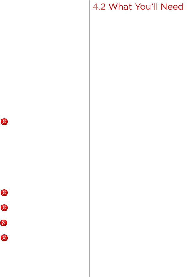
Gather the recommended tools and parts before starting installation.
Items Needed
•Pressure relief valve for domestic hot water (150 PSI / 1,034 kPa)
•Low loss header or closely spaced tee
•Expansion tank for a closed heating system
•Isolation valve kit or equivalent components (for quick isolation of the boiler for service and/or maintenance)
•CH System Air Separator
•Standard tools for central heating, gas fitting, plumbing and electrical wiring.
•Combustion analyzer (intended for use with condensing boilers)
•Digital manometer capable of reading both positive and negative pressure
•Digital multimeter capable of reading microamps
•pH digital meter or test strips
•For wall mounting bracket installation:
−Level
−Screws (use appropriate screws for type of wall construction)
Other Items You May Need
•Hand truck with fastening belt
•Boiler toolkit (optional accessory for boiler service. See section “3.6 Accessories” for more information.)
Rinnai M-Series Condensing Boiler Combi Manual

Carefully unpack your boiler system and verify the following contents are included. If any items are damaged or missing, contact your local dealer/distributor. Do not attempt to use any item that appears damaged.
RINNAI CONDENSING BOILER
Vent top with integrated 3 in. PP (80 mm) Connections
Integrated
Items
Pump |
Refer to section |
|
“3.3 Components” |
||
|
||
|
for a complete list of |
|
|
integrated parts. |
WALL MOUNTING |
|
30 PSI PRESSURE |
|
OUTDOOR |
CENTRAL HEATING |
BRACKET |
|
RELIEF VALVE |
|
TEMPERATURE SENSOR |
TEMPERATURE |
|
|
|
PRESSURE GAUGE |
||
|
|
For Central |
|
|
|
|
|
|
|
|
|
|
|
Heating Systems |
|
|
|
|
|
|
|
|
|
VENT ADAPTERS
3 in. PVC |
2 in. PVC/PP |
(QTY 2) |
Reducer (QTY 2) |
3/5 in. Concentric
LIQUID PROPANE FIELD CONVERSION KIT
This boiler is configured for Natural Gas only. Use this kit to convert to Propane Gas if needed. Contents include:
EEPROM KEY LIQUID PROPANE CONVERSION CONVERSION
RESTRICTOR RATING MANUAL PLATE
DOCUMENTATION
• |
Installation and Operation |
• |
ISCL |
|
Manual (this manual) |
• |
Conversion Manual |
• |
User Manual |
|
|
Rinnai M-Series Condensing Boiler Combi Manual |
17 |
When choosing an installation location, you must ensure that clearances will be met and that the vent length will be within required limits. Consider the installation environment, water quality, and need for freeze protection. Requirements for the gas line, water lines, electrical connection, and condensate disposal can be found in their respective installation sections in this manual.
This section provides information on the importance of water quality to the Rinnai Condensing Boiler. The information is intended to serve as general guidelines only and is not a complete list of water quality guidelines.
Consideration of care for your boiler should include evaluation of water quality.
•The water must be potable, free of corrosive chemicals, sand, dirt, or other contaminants.
•It is up to the installer to ensure the water does not contain corrosive chemicals or elements that can affect or damage the boiler.
•Water that contains chemicals exceeding the levels below can damage the boiler.
Contaminant |
Maximum Level |
|
Total Hardness |
Up to 200 mg/L |
|
Aluminum * |
Up to 0.2 mg/L |
|
Chlorides * |
Up to 250 mg/L |
|
Copper * |
Up to 1.0 mg/L |
|
Dissolved Carbon Dioxide |
Up to 15.0 mg/L |
|
(CO2) |
||
|
||
Iron * |
Up to 0.3 mg/L |
|
Manganese * |
Up to 0.05 mg/L |
|
pH * |
6.5 to 8.5 |
|
TDS (Total Dissolved Solids)* |
Up to 500 mg/L |
|
Zinc * |
Up to 5 mg/L |
* Source: Part 143 National Secondary
Drinking Water Regulations
•Unsuitable heating system water can cause the formation of scale or sludge, which affects system efficiency. It can also cause corrosion and reduce life of the heat exchanger.
•Never use water that has been treated by a reverse osmosis, deionized, or distilled water to soften the water to fill the heating system.
•For Domestic Hot Water systems, if you install the boiler in an area that is known to have hard water or that causes scale buildup, the water must be treated and may require a more frequent flushing schedule. Scale build-up is caused by hard water and can be accelerated if the boiler is set at a high temperature. Rinnai offers Southeastern Filtration’s “ScaleCutter Water Conditioning System” that offers superior lime scale prevention and corrosion control by feeding a blend of control compounds into the cold water supply.
•Oxygen permeable or rubber tubing is not permitted in the heating system unless it is separated from the boiler by a plate heat exchanger. The boiler warranty may be voided if connected directly to CH systems that include this tubing.
•Thoroughly flush the system prior to filling. While flushing, isolate the boiler.
•Do not introduce any system cleaner into the boiler. Flush the system thoroughly to remove all system cleaner before filling the boiler with water.
•When freeze protection of the heating system is desired, only use Rinnai-approved antifreezes. The allowed maximum concentration is 50%.
•Reference section “14.1 Approved Cleaners, Inhibitors and Antifreezes” in the Appendix for an approved list of system cleaners, inhibitors, and antifreezes.
 IMPORTANT
Replacement of components due to water quality damage is not covered by the warranty.
18 |
Rinnai M-Series Condensing Boiler Combi Manual |

Air surrounding the boiler, venting, and vent termination(s) is used for combustion and must be free of any compounds that cause corrosion of internal components. These include corrosive compounds that are found in aerosol sprays, detergents, bleaches, cleaning solvents, oil based paints/varnishes, and refrigerants. The air in beauty shops, dry cleaning stores, photo processing labs, and storage areas for pool supplies often contains these compounds. The boiler, venting, and vent termination(s) should not be installed in any areas where the air may contain these corrosive compounds.
Location |
Clearance |
|
|
Top |
2 in. (51 mm) |
|
0 in. from vent components |
Bottom (Ground) |
12 in. (305 mm) |
Front |
6 in. (152 mm) |
|
Clearance for servicing is |
|
24 in. (610 mm) in front |
|
of boiler |
|
|
Back |
0 in. |
Sides (Left and Right) |
2 in. (51 mm) |
Vent |
0 in. |
|
|
Right image is not to scale and is for illustration purposes only.
Top
Front
Side
Bottom
WALL
2 in. (51 mm) Minimum
2 in. (51 mm) Minimum
12 in. (305 mm) Minimum
Use this checklist to ensure you have selected the correct location for the boiler.
□The boiler is not exposed to corrosive compounds in the air.
□The boiler location complies with the required clearances.
□The planned combustion air and exhaust termination locations meet the required clearances.
□The water supply does not contain chemicals or exceed total hardness that will damage the heat exchanger.
□A standard 3 prong 120 VAC, 60 Hz properly grounded wall outlet or other 120 VAC, 60 Hz source is available.
□The installation must conform with local codes or, in the absence of local codes, with the
National Fuel Gas Code, ANSI Z223.1/NFPA 54, or the Natural Gas and Propane Installation Code, CSA B149.1.
Rinnai M-Series Condensing Boiler Combi Manual |
19 |
You Will Need:
•Rinnai Condensing Boiler
•Wall Mounting Bracket
•Boiler Mounting Template
Supplied by Installer:
•Level
•Four screws for mounting bracket installation
•Screws for top and bottom bracket installation
Use appropriate screws for type of wall construction.
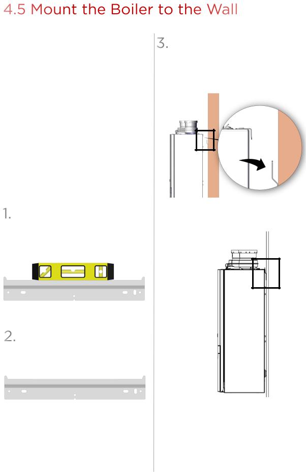
Instructions:
Hold the wall mounting bracket up against the wall and use a level to make sure the bracket is even. Proper operation requires the boiler to be level.
Level
Wall Mounting Bracket
Use the appropriate screws for the wall construction to secure the mounting bracket to the wall (use any of the screw holes in the mounting bracket).
Insert the top mounting lip of the boiler onto the wall mounting bracket. Make sure the wall mounting bracket is attached to the wall and can hold the weight of the boiler before you fully let go.
Boiler mounting template
Assembled view
20 |
Rinnai M-Series Condensing Boiler Combi Manual |
5
Topics in this section
•Guidelines
•Venting Installation Sequence
•Termination Considerations
•Venting Options
•M-Series boilers can be installed in direct vent or non-direct vent applications.
•When installed as Direct Vent, refer to the following section for a complete list of approved vent manufacturers and products: “5.4.1 Direct Vent: Approved Vent Manufacturers and Products.”
•When installed as Non-Direct Vent (Room Air), the vent must be Category IV and of a type listed by a national recognized testing agency.
•Exhaust must be directly vented to the outside. Combustion air can be provided from outside (Direct Vent) or from room air (Non-Direct Vent).
•If using room air (non-direct vent) for combustion, ensure the required volume of indoor air is available according to the National Fuel Gas Code, ANSI Z223.1/NFPA 54.
•Avoid dips or sags in horizontal vent runs by installing supports per the vent manufacturer’s instructions.
•Support horizontal vent runs every 4 ft (1.2 m) and all vertical vent runs every 6 ft (1.83 m) or as per vent manufacturer’s instructions or local code requirements.
Rinnai M-Series Condensing Boiler Combi Manual
•Venting should be as direct as possible with a minimum number of pipe fittings.
•For manufactured vent systems, vent connections must be firmly pressed together so that the connections form an air tight seal. Follow the venting manufacturer’s instructions.
•Refer to the Schedule 40 PVC/CPVC manufacturer for appropriate fittings, solvents or joining methods.
•If venting reassembly is needed, follow the steps for installing the venting in the following sections. Make certain that the vent piping and seals are not damaged. Only use sealants, primers, or glues that are approved for the vent material in use.
•Refer to the instructions of the vent system manufacturer for component assembly instructions.
•If the vent system is to be enclosed, it is suggested that the design of the enclosure shall permit inspection of the vent system. The design of such enclosure shall be deemed acceptable by the installer or the local inspector.
•Any issues resulting from improper vent installation will not be covered by warranty.
 WARNING
•DO NOT use cellular core PVC/CPVC.
•DO NOT use Radel, ABS, or galvanized material to vent this appliance.
•DO NOT cover non-metallic vent pipe and fittings with thermal insulation.
•DO NOT combine vent components from different manufacturers.
•DO NOT reduce the vent diameter. Vent diameter cannot be less than 2 in.
•DO NOT connect the venting system with an existing vent or chimney.
•DO NOT common vent with the vent pipe of any other manufacturer’s boiler or appliance.
21

1.Determine the termination method— horizontal or vertical, concentric, or twin pipes, etc.
2.Determine proper location for wall or roof penetration for each termination.
3.Install termination assembly as described in this manual or in the vent manufacturer’s installation instructions.
4.Install air and vent piping from boiler to termination.
5.Slope horizontal exhaust run towards the boiler 1/4 in. per foot. DO NOT slope combustion air pipe towards boiler.
6.Install vent supports and brackets allowing for movement from expansion, or as per vent manufacturer’s instructions or local code requirements.
7.(Optional step) Install vent screen or room air filter (not included with purchase) on Schedule 40 PVC combustion air and exhaust termination elbows as illustrated below.
Vent Screen
Room Air Filter
•Press vent screen inside of termination piece/ elbow.
•Secure vent screen to the elbow with screw.
Press air filter into the 3 in. (80 mm) PP intake air fitting on the boiler.
Check to determine whether local codes supersede the following clearances:
•Avoid termination locations near a dryer vent.
•Avoid termination locations near commercial cooking exhaust.
•Avoid termination locations near any air inlets.
•You must install a vent termination at least 12 in above the ground or anticipated snow level.
The vent for this appliance shall not terminate:
•Over public walkways.
•Near soffit vents or crawl space vents or other area where condensate or vapor could create a nuisance or hazard or cause property damage.
•Where condensate or vapor could cause damage or could be detrimental to the operation of regulators pressure relief valves, or other equipment.
Listed below are important considerations for locating vent termination under a soffit (ventilated or unventilated or eave vent; or to a deck or porch):
•Do not install vent termination under a soffit vent such that exhaust can enter the soffit vent.
•Install vent termination such that exhaust and rising moisture will not collect under eaves. Discoloration to the exterior of the building could occur if installed too close.
•Do not install the vent termination too close under the soffit where it could present recirculation of exhaust gases back into the combustion air intake of the termination.
Horizontal portions of the venting system shall be supported to prevent sagging:
•For category IV boilers, have horizontal runs sloping upwards not less than 1/4 in. per foot (21 mm/m) from the boiler to the vent terminal;
•For category IV boilers, be installed so as to prevent accumulation of condensate; and
•For category IV boilers, where necessary, have means provided for drainage of condensate.
22 |
Rinnai M-Series Condensing Boiler Combi Manual |
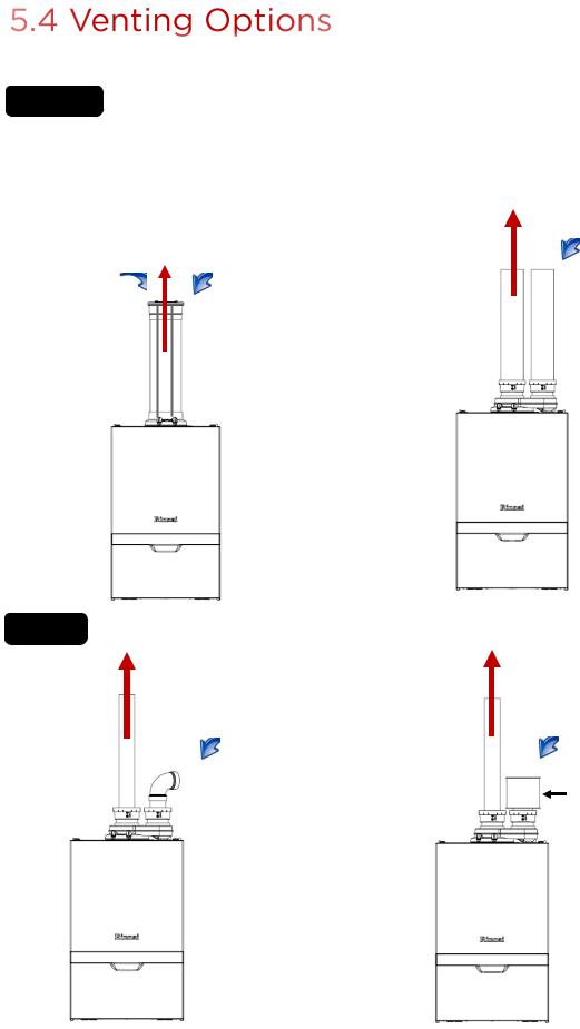
Two venting options are available: Direct Vent and Non-Direct Vent (Room Air).
Option 1 |
Direct Vent (Concentric and Twin Pipe) |
See Direct Vent section for complete details. |
|
Concentric Pipe |
Twin Pipe |
Combustion air and exhaust vent directly through a single concentric connection. Hot exhaust exits through the interior tube, while combustion air enters through the outer layer.
|
Exhaust |
Combustion |
Combustion |
air |
air |
Combustion air and exhaust vent directly through separate penetrations.
Exhaust
Combustion
air
Option 2 |
Room Air |
See Room Air section for complete details. |
|
|
|
Exhaust |
Exhaust |
|
Combustion |
Combustion air |
air |
|
|
Room air filter |
|
(accessory) |
Rinnai M-Series Condensing Boiler Combi Manual |
23 |
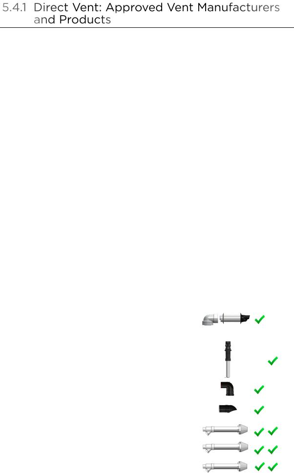
Following is a list of vent components and terminations for Direct Vent installations (concentric and twin pipe). Install the correct venting for your model according to the venting manufacturer’s instructions and the guidelines below. The information below is correct at time of publication and is subject to change without notice. Contact the vent manufacturer for questions related to the vent system, products, part numbers and instructions.
Manufacturer |
Phone |
Web Site |
Ubbink |
800-621-9419 |
www.rinnai.us |
|
|
|
Centrotherm |
877-434-3432 |
www.centrotherm.us.com |
|
|
|
Heat-Fab |
800-772-0739 |
www.heatfab.com |
|
|
|
Metal Fab |
800-835-2830 |
www.metal-fabinc.com |
|
|
|
IPEX |
U.S.: 800-463-9572 |
www.ipexamerica.com, www.ipexinc.com |
|
Canada: 866-473-9462 |
|
|
|
|
DuraVent |
800-835-4429 |
www.duravent.com |
|
|
|
Royal |
800-232-5690 |
www.royalbuildingproducts.com |
|
|
|
ECCO Manufacturing |
877-955-4805 |
www.eccomfg.com |
|
|
|
DiversiTech |
800-995-2222 |
www.diversitech.com |
|
|
|
Z-FLEX |
603-669-5136 |
www.z-flex.com |
|
|
|
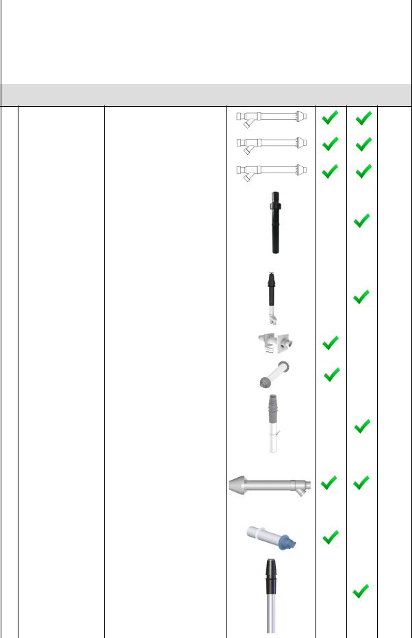
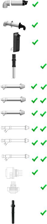
2 in./4 in. CONCENTRIC VENT TERMINATIONS
Manufacturer |
Manufacturer Part Number |
Product Description |
Diagram |
Horizontal |
Vertical |
Equivalent Length (ft) |
|
|
|
|
|
|
|
|
|
2 in./4 in. CONCENTRIC VENT TERMINATIONS |
|
|
|
|
|
|
|
|
|
|
|
|
229011NPP |
2/4 Condensing Horizontal Termination Kit 8.7 in. |
|
|
|
|
|
229012NPP |
2/4 Condensing Horizontal Termination Kit 12 in. |
|
|
|
5 |
|
229013NPP |
2/4 Condensing Horizontal Termination Kit 21 in. |
|
|
|
|
|
|
|
|
|
|
|
UBBINK |
224356NPP |
2/4 Condensing Roof Discharge Termination |
|
|
|
|
|
20 in. above roof |
|
|
|
5 |
|
|
|
|
|
|
||
|
|
|
|
|
|
|
|
|
|
|
|
|
|
|
710202NPP |
2/4 Condensing 90 Degree Diverter Nose |
|
|
|
5 |
|
|
(Use with Wall Terminal) |
|
|
|
|
|
|
|
|
|
|
|
|
|
|
|
|
|
|
|
710215NPP |
2/4 Condensing 45 Degree Diverter Nose |
|
|
|
5 |
|
|
(Use with Wall Terminal) |
|
|
|
|
|
|
|
|
|
|
|
|
|
|
|
|
|
|
|
196005, |
FGV Concentric Vent Kit (16 in. length) |
|
|
|
20 |
|
197040 |
|
|
|
|
|
IPEX |
|
|
|
|
|
|
|
|
|
|
|
|
|
196105, |
FGV Concentric Vent Kit (28 in. length) |
|
|
|
20 |
|
197033 |
|
|
|
|||
|
|
|
|
|
|
|
|
|
|
|
|
|
|
|
196125 |
FGV Concentric Vent Kit (40 in. length) |
|
|
|
20 |
|
|
|
|
|
|
|
24 |
|
Rinnai M-Series Condensing Boiler Combi Manual |
|
|||
Manufacturer |
Manufacturer |
Part Number |
Product |
Description |
Diagram |
Horizontal |
Vertical |
Equivalent Length |
(ft) |
|
|
|
|
|
|
|
|
|
|
2 in./4 in. CONCENTRIC VENT TERMINATIONS (Continued)
52CVKGVS6502 |
PVC Concentric Vent Kit |
20 |
|
2 in. x 16 in. |
|
|
|
ROYAL |
|
|
|
|
52CVKGVS6502-28 |
PVC Concentric Vent Kit |
20 |
||
|
||||
|
|
2 in. x 28 in. |
||
|
|
|
||
|
|
|
|
|
|
52CVKGVS6502-40 |
PVC Concentric Vent Kit |
20 |
|
|
|
2 in. x 40 in. |
||
|
|
|
||
|
|
|
|
|
CENTROTHERM |
ICRT2439 |
2 in. x 4 in. Concentric Roof |
|
|
|
|
|||
|
|
Termination |
|
|
|
|
|
20 |
|
|
|
|
|
|
|
2PPS-VKL/VK-TCL |
2 in. x 4 in. Vertical |
|
|
DURAVENT |
|
Termination Cap |
20 |
|
|
Kit-Concentric |
|||
|
|
|||
|
|
|
||
|
|
|
|
|
|
2PPS-HKL |
2 in. x 4 in. Horizontal |
20 |
|
|
|
Termination Kit-Concentric |
||
|
|
|
||
|
|
|
|
|
|
190288 |
2 in. x 4 in. Concentric |
5 |
|
|
|
Horizontal Termination |
||
ECCO |
|
|
|
|
190295 |
2 in. x 4 in. Concentric |
|
||
|
Vertical Termination |
|
||
|
|
|
5 |
|
|
|
|
|
|
DIVERSITECH |
CVENT-2 |
2 in. x 4 in. Concentric |
|
|
|
|
|||
|
|
Horizontal Termination |
|
|
|
|
|
20 |
|
|
|
|
|
|
|
2ZDCTH24 |
2 in. x 4 in. Concentric |
5 |
|
|
|
Horizontal Termination |
||
|
|
|
|
|
FLEX-Z |
2ZDCTV24 |
2 in. x 4 in. Concentric Roof |
|
|
|
Termination |
|
||
|
|
|
||
|
|
|
5 |
|
|
|
|||
Rinnai M-Series Condensing Boiler Combi Manual |
25 |
|||
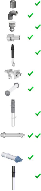
3 in./5 in. CONCENTRIC VENT TERMINATIONS
Manufacturer |
Manufacturer Part Number |
Product Description |
Diagram |
Horizontal |
Vertical |
Equivalent Length (ft) |
|
|
|
|
|
|
|
|
3 in./5 in. CONCENTRIC VENT TERMINATIONS |
|
|
|
||
|
223174PP |
3/5 Condensing Horizontal |
|
|
|
|
|
223176PP |
Termination Kit 8.7 in. |
|
|
|
|
|
223177PP |
3/5 Condensing Horizontal |
|
|
|
5 |
|
|
Termination Kit 12 in. |
|
|
|
|
|
|
|
|
|
|
|
|
|
3/5 Condensing Horizontal |
|
|
|
|
|
|
Termination Kit 21 in. |
|
|
|
|
UBBINK |
|
|
|
|
|
|
223186PP |
3/5 Condensing Horizontal Diverter |
|
|
|
16 |
|
|
Termination Kit 19 in. |
|
|
|
||
|
|
|
|
|
||
|
|
|
|
|
|
|
224047PP |
3/5 Condensing Raised Horizontal |
|
|
|
|
|
|
|
Termination Kit |
|
|
|
24 |
|
|
|
|
|
|
|
|
|
|
|
|
|
|
|
184162PP |
3/5 Condensing Roof Discharge |
|
|
|
|
|
|
Termination 20 in. above roof |
|
|
|
|
|
|
|
|
|
|
5 |
|
|
|
|
|
|
|
|
196006, 197009 |
FGV Concentric Vent Kit 3 in. x 20 |
|
|
|
20 |
|
|
in. |
|
|
|
|
|
|
|
|
|
|
|
|
|
|
|
|
|
|
IPEX |
196106, 197107 |
FGV Concentric Vent Kit 3 in. x 32 |
|
|
|
20 |
|
in. |
|
|
|
||
|
|
|
|
|
|
|
|
|
|
|
|
|
|
|
196116, 197117 |
FGV Concentric Vent Kit 3 in. x 44 |
|
|
|
20 |
|
|
in. |
|
|
|
|
|
|
|
|
|
|
|
|
|
|
|
|
|
|
|
52CVKGVS6503 (PVC)/ |
PVC/CPVC Concentric Vent Kit 3 in. |
|
|
|
20 |
|
52CVKGVSF9003 (CPVC) |
x 20 in. |
|
|
|
|
|
|
|
|
|
||
|
|
|
|
|
|
|
ROYAL |
52CVKGVS6503-32 |
PVC/CPVC Concentric Vent Kit 3 in. |
|
|
|
|
(PVC)/ 52CVKGVSF9003- |
x 32 in. |
|
|
|
20 |
|
|
32 (CPVC) |
|
|
|
|
|
|
|
|
|
|
|
|
|
52CVKGVS6503-44 |
PVC/CPVC Concentric Vent Kit 3 in. |
|
|
|
|
|
(PVC)/ 52CVKGVSF9003- |
x 44 in. |
|
|
|
20 |
|
44 (CPVC) |
|
|
|
|
|
FAB |
SC03HT |
Horizontal Termination Adapter |
|
|
|
20 |
|
|
|
|
|
||
|
|
|
|
|
|
|
HEAT- |
|
|
|
|
|
|
SC03VT |
Vertical Termination Adapter |
|
|
|
20 |
|
|
|
|
|
|||
|
|
|
|
|
|
|
|
|
|
|
|
|
|
CENTROTHERM |
ICRT3539 |
3 in./5 in. Concentric Roof |
|
|
|
|
|
|
|
|
|
||
|
|
Termination PPs-UV |
|
|
|
|
|
|
|
|
|
|
20 |
|
|
|
|
|
|
|
26 |
Rinnai M-Series Condensing Boiler Combi Manual |
Manufacturer |
Manufacturer Part Number |
Product Description |
Diagram |
Horizontal |
Vertical |
|
Equivalent Length (ft) |
|
|
|
|
|
|
|
|
|
3 in./5 in. CONCENTRIC VENT TERMINATIONS (Continued) |
|
|
|
|||
|
3CGRLSV |
Vertical Adapter |
|
|
|
|
1 |
|
|
|
|
|
|
|
|
|
|
|
|
|
|
|
|
FAB- |
3CGRLSH |
Horizontal Adapter |
|
|
|
|
6 |
|
|
|
|
|
|
||
|
|
|
|
|
|
|
|
METAL |
|
|
|
|
|
|
|
3CGRVT |
Vertical Termination |
|
|
|
|
5 |
|
|
|
|
|
|
|||
|
|
|
|
|
|
|
|
|
|
|
|
|
|
|
|
|
3CGRHT |
Horizontal Termination |
|
|
|
|
16 |
|
|
|
|
|
|
|
|
|
|
|
|
|
|
|
|
|
3PPS-VKL/VK-TCL |
3 in. x 5 in. Vertical Termination Cap |
|
|
|
|
|
DURAVENT |
|
Kit-Concentric |
|
|
|
|
|
|
|
|
|
|
|
20 |
|
|
|
|
|
|
|
|
|
|
|
|
|
|
|
|
|
|
3PPS-HKL |
3 in. x 5 in. Horizontal Termination |
|
|
|
|
20 |
|
|
Kit-Concentric |
|
|
|
|
|
|
|
|
|
|
|
|
|
|
|
|
|
|
|
|
|
|
190388 |
3 in. x 5 in. Concentric |
|
|
|
|
|
|
|
Horizontal Termination |
|
|
|
|
5 |
|
|
|
|
|
|
|
|
ECCO |
|
|
|
|
|
|
|
190395 |
3 in. x 5 in. Concentric Vertical |
|
|
|
|
|
|
|
Termination |
|
|
|
|
|
|
|
|
|
|
|
|
|
5 |
|
|
|
|
|
|
|
|
DIVERSITECH |
CVENT-3 |
3 in. x 5 in. Concentric |
|
|
|
|
|
|
|
|
|
|
|
||
|
|
Horizontal Termination |
|
|
|
|
20 |
|
|
|
|
|
|
|
|
|
|
|
|
|
|
|
|
|
2ZDCTH35 |
3 in. x 5 in. Concentric |
|
|
|
|
|
|
|
Horizontal Termination |
|
|
|
|
5 |
|
|
|
|
|
|
|
|
FLEX-Z |
2ZDCTV35 |
3 in. x 5 in. Concentric Roof |
|
|
|
|
|
|
Termination |
|
|
|
|
|
|
|
|
|
|
|
|
|
|
|
|
|
|
|
|
|
5 |
|
|
|
|
|
|
|
|
Rinnai M-Series Condensing Boiler Combi Manual |
|
|
|
27 |
|||
2 in. TWIN PIPE TERMINATIONS
Manufacturer |
Manufacturer |
Part Number |
Product |
Description |
Diagram |
Horizontal |
Vertical |
Equivalent Length (ft) |
|
|
|
|
|
|
|
|
|
2 in. TWIN PIPE TERMINATIONS
CENTROTHERM |
ISELL0287UV |
Termination |
|
|
|
5 |
|
2 in. 87° Long PPS-UV |
|
|
|
6 |
|
|
|
|
|
|
|
|
|
|
|
|
|
|
|
|
ISTT0220 |
2 in. Termination Tee |
|
|
|
6 |
|
|
|
|
|
|
|
|
|
|
|
|
|
|
|
ISLPT0202 |
2 in. Low Profile Wall |
|
|
|
|
|
|
|
|
|
|
|
|
2PPS-HTPL |
2 in. Twin Pipe Termination |
|
|
|
10 |
DURAVENT |
|
|
|
|
|
|
|
|
|
|
|
|
|
2PPS-HSTL |
2 in. Single Horizontal |
|
|
|
6 |
|
|
|
|
|
|||
|
|
Termination |
|
|
|
|
|
|
|
|
|
|
|
|
|
|
|
|
|
|
|
2PPS-TBL |
2 in. Black UV Resistant Tee |
|
|
|
5 |
|
|
|
|
|
|
|
|
|
|
|
|
|
|
|
196984 |
FGV PVC Low Profile |
|
|
|
|
|
|
Termination Kit |
|
|
|
5 |
IPEX |
|
|
|
|
|
|
|
Kit |
|
|
|
|
|
|
081216 |
FGV PVC Wall Termination |
|
|
|
|
|
|
|
|
|
|
16 |
|
|
|
|
|
|
|
|
52SWVKGVS6502 |
PVC Side Wall Vent Kits |
|
|
|
|
|
|
|
|
|
|
5 |
ROYAL |
|
|
|
|
|
|
52WTVKGVS6502 |
PVC Wall Vent Kits |
|
|
|
|
|
|
|
|
|
|
||
|
|
|
|
|
|
16 |
|
|
|
|
|
|
|
DIVERSITECH |
HVENT-2 |
2 in. Low Profile Horizontal |
|
|
|
|
|
|
Vent Kit |
|
|
|
|
|
|
|
|
|
|
5 |
|
|
|
|
|
|
|
28 |
Rinnai M-Series Condensing Boiler Combi Manual |
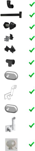
3 in. TWIN PIPE TERMINATIONS
Manufacturer |
Manufacturer Part Number |
Product Description |
Diagram |
Horizontal |
Vertical |
Equivalent Length (ft) |
|
|
|
|
|
|
|
|
|
3 in. TWIN PIPE TERMINATIONS |
|
|
|
|
|
|
|
|
|
|
|
CENTROTHERM |
ISELL0387UV |
3 in. 87° Long PPS-UV |
|
|
|
6 |
|
|
|
|
|
||
|
|
|
|
|
|
|
ISTT0320 |
3 in. Termination Tee |
|
|
|
6 |
|
|
|
|
|
|||
|
|
|
|
|
|
|
|
|
|
|
|
|
|
|
ISLPT0303 |
3 in. Low Profile Wall |
|
|
|
5 |
|
|
Termination |
|
|
|
|
|
|
|
|
|
|
|
|
|
|
|
|
|
|
|
3PPS-HTPL |
3 in. Twin Pipe Termination |
|
|
|
10 |
|
|
|
|
|
|
|
DURAVENT |
|
|
|
|
|
|
3PPS-HSTL |
3 in. Single Horizontal |
|
|
|
5 |
|
|
|
|
|
|||
|
|
Termination |
|
|
|
|
|
|
|
|
|
|
|
|
|
|
|
|
|
|
|
3PPS-TBL |
3 in. Black UV Resistant Tee |
|
|
|
6 |
|
|
|
|
|
|
|
|
|
|
|
|
|
|
|
196985 |
FGV PVC Low Profile |
|
|
|
5 |
|
|
Termination Kit |
|
|
|
|
IPEX |
|
|
|
|
|
|
081219 |
FGV PVC Wall |
|
|
|
|
|
|
|
|
|
|
||
|
|
Termination Kit |
|
|
|
16 |
|
|
|
|
|
|
|
|
|
|
|
|
|
|
|
52SWVKGVS6503 |
PVC Side Wall Vent Kits |
|
|
|
5 |
|
|
|
|
|
|
|
ROYAL |
|
|
|
|
|
|
52WTVKGVS6503 |
PVC Wall Vent Kits |
|
|
|
|
|
|
|
|
|
|
||
|
|
|
|
|
|
16 |
|
|
|
|
|
|
|
DIVERSITECH |
HVENT-3 |
3 in. Low Profile Horizontal |
|
|
|
|
|
|
|
|
|
||
|
|
Vent Kit |
|
|
|
|
|
|
|
|
|
|
5 |
|
|
|
|
|
|
|
Rinnai M-Series Condensing Boiler Combi Manual |
29 |

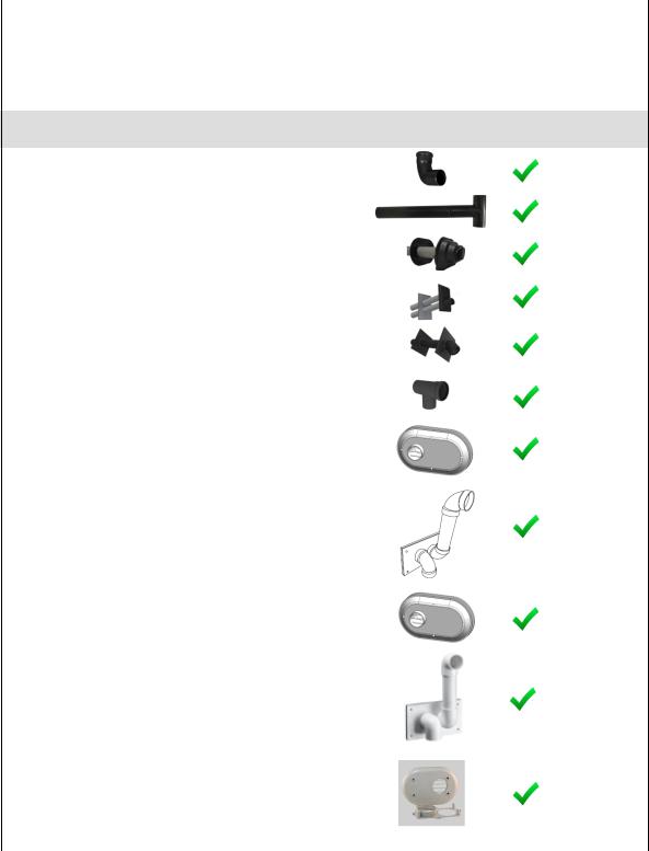
VARIOUS 2 in. OR 3 in. SCHEDULE 40 PVC/CPVC TERMINATIONS
Product |
Description |
|
Diagram |
|
Horizontal |
|
Vertical |
|
Equivalent Length (ft) |
|
|
|
|
|
|
|
|
|
|
|
|
Air Filter Screen |
|
|
|
|
|
|
|
|
N/A |
|
|
|
|
|
|
|
|
|
|
|
|
Tee |
|
|
|
|
|
|
|
|
5 |
|
|
|
|
|
|
|
|
|
|
|
|
90° Elbow |
|
|
|
|
|
|
|
|
5 |
|
|
|
|
|
|
|
|
|
|
|
|
45° Elbow |
|
|
|
|
|
|
|
|
2.5 |
|
|
|
|
|
|
|
|
|
|
|
|
|
|
|
|
|
|
|
|
|
|
|
|
|
Approved PVC/CPVC Vent and Air Piping Material |
|
|
|
|||||
|
|
|
|
|
|
|
|
|
|
|
Item |
|
Material |
|
Standard for Installation in North America |
|
|||||
|
United States |
|
Canada |
|
|
|
||||
|
|
|
|
|
|
|
||||
|
|
Thermoplastic Piping Materials |
|
|
|
|
|
|
||
Vent or Combustion |
|
PVC Schedule 40 |
ANSI/ASTM D1785 |
Thermoplastic vent pipe must |
||||||
Air Intake Pipe and |
|
PVC-DWV |
ANSI/ASTM D2665 |
|||||||
|
be certified to ULC S636. |
|||||||||
Fittings |
|
CPVC Schedule 40 |
ANSI/ASTM F441 |
|||||||
|
Intake pipe may be of the |
|||||||||
PVC Pipe Cement |
|
PVC |
ANSI/ASTM D2564 |
|||||||
|
materials listed in this table. |
|||||||||
and Primer |
|
CPVC Schedule 40 |
ANSI/ASTM F493 |
|||||||
|
|
|
|
|
|
|
||||
|
|
PVC Vent Screens |
|
|
|
|
|
|
||
|
|
|
• 2 in. Vent Screens (included in carton box) (IPEX |
|||||||
Termination Vent |
|
Polyethylene |
Part Number: 196050) |
|
|
|
||||
Screens |
|
• 3 in. Vent Screens (IPEX Part Number: 196051) |
|
|||||||
|
|
|
||||||||
|
|
|
|
|||||||
|
|
|
|
|
|
|
|
|
|
|
Exhaust piping must be of solid core material. Refer to the PVC/CPVC manufacturer for appropriate fittings, solvents or joining methods.
APPROVED VENTING MATERIALS BY MANUFACTURER
Manufacturer |
Vent Material |
|
Ubbink |
PVC (Outer Vent), Polypropylene (Inner Vent) |
|
|
|
|
Centrotherm |
Polypropylene |
|
|
|
|
Heat-Fab |
Metal |
|
|
|
|
Metal Fab |
Metal |
|
|
|
|
IPEX |
PVC/CPVC |
|
|
|
|
DuraVent |
Polypropylene |
|
|
|
|
Royal |
PVC |
|
|
|
|
ECCO Manufacturing |
Polypropylene |
|
|
|
|
DiversiTech |
PVC/CPVC |
|
|
|
|
Z-FLEX |
Polypropylene |
|
|
|
|
30 |
Rinnai M-Series Condensing Boiler Combi Manual |
|
 Loading...