


E110CP
I n s t a l l a t i o n & S e r v i c i n g
Instructions
High efciency condensing gas boiler
E75CN/E110CN
E75CP/E110CP
CAUTION!
Read this manual thoroughly before installing, servicing, putting
into operation or using this boiler and vent system.
WARNING!
Improper installation, adjustment, alteration, service or
maintenance can cause property damage, personal injury or
loss of life. Refer to this manual. For assistance or additional
information consult a qualied installer or the gas supplier.
CAUTION!
The user manual is part of the documentation that is delivered
to the installation's operator. Go through the information in this
manual with the owner/operator and make sure that he or she is
familair with all necessary operating instructions.
NOTICE!
Installation and service must be performed by a qualied
installer, service technician or the gas supplier.
Pictured: E75CN, E110CN
E75CP, E110CP
In the Commonwealth of Massachusetts this boiler must be
installed by a licensed Plumber or Gas Fitter.
WARNING!
If you do not follow these instructions exactly, a re or explosion may
result causing property damage, personal injury or loss of life.
- Do not store or use gasoline or other ammable vapors and
liquids in the vicinity of this or any other appliance.
- WHAT TO DO IF YOU SMELL GAS
- Do NOT try to light any appliance.
- Do NOT touch any electrical switch.
- Do NOT use any phone in your building.
- Immediately call your gas supplier from a neighbor’s phone.
Follow the gas supplier’s instructions.
- If you cannot reach your gas supplier, call the re department.
Address: 103 International Drive, Peachtree City, GA, 30269
Toll-free: 1-800-621-9419 • Fax: 678-829-1666 • www.rinnai.us
These instructions to be retained by user.
8U.51.60.01/09.09 Changes reserved.

Contents of instructions
These installation instructions contain important information for the safe installation, start-up and maintanance of
boilers with capacities 75,000 through 110,000 BTU/hr.
These installation instructions are intended for professional installers, who have the necessary knowledge and are
approved for working on heating and gas systems.
Subject to technical changes
Changes may be made without notice to the illustrations, process steps and technical data as a result of our policy
of continuous improvement.
Updating of documentation
Please contact us if you have any suggestions for improvements or corrections.
Find our contact details on the back of this manual.
California Proposition 65 lists chemical substances known to the state to cause cancer, birth defects, death,
serious illness or other reproductive harm. This product may contain such substances, be their origin from fuel
combustion (gas, oil) or components of the product itself.
Installation & Servicing Instructions Rinnai E-Series
2

Content
1 Safety and general instructions 4
1.1 Designated use 4
1.2 Hazard denitions 4
1.3 Symbol denitions 4
1.4 The following instructions must be followed 5
1.5 Follow these instructions for the space heating water 6
1.6 Tools, materials and additional equipment 6
1.7 Relevant Installation, Service and User manuals 6
1.8 Disposal 6
2 Regulations and guidelines 7
3 Description of the boiler 8
4 Packaging and transportation 9
4.1 Scope of delivery 9
4.2 Transportation 9
5 Installation 10
5.1 Requirements for the installation room 10
5.2 Fitting the boiler 11
5.3 Dimensions 12
5.3.1 Plumbing kits 14
5.3.2 Clearances from appliance 15
5.4 Technical specications 16
6 Connecting the boiler 17
6.1 Central heating system 17
6.1.1 Plumbing Kit installation 18
6.1.2 Safety valve 19
6.1.3 Low water cut off 20
6.2 Expansion tank 20
6.3 Underoor heating system (plastic pipes) 21
6.4 Gas supply connection 21
6.4.1. Gas connection with natural gas 22
6.4.2 Gas connection with propane gas 23
6.5 Hot water supply 24
6.6 Condensate drain pipe 24
6.7 Vent system and air supply system 25
6.7.1 Intake / Exhaust Guidelines 25
6.7.2 Examples vent and air supply systems 26
6.7.3 Installation of the vent system 28
6.7.4 Recommended vent/air intake terminal position 29
6.7.5 Dimensioning of the exhaust and air intake duct 31
6.7.6 Combustion air and vent piping lengths 32
6.7.7 Calculation of compensation factor 33
6.7.8 Room Air System (outdoor combustion air) 34
7 Electrical connections 37
8 Boiler controls 40
8.1 Explanation of the function buttons 41
9 Starting up: Filling and de-aerating the boiler and installation 42
9.1 Requirements of the water system 42
9.2 Filling the heating system 43
9.3 Hot water supply 44
10 Adjustments 46
10.1 Altering adjustments 46
10.2 Activating factory settings (green button function) 49
11 Isolating the boiler 49
12 Commissioning 50
12.1 Testing for gas leaks 51
12.2 Testing the Ignition Safety shut off device 51
12.3 Checking for contamination 52
12.4 Checking of the zero pressure control 53
12.5 Checking the O
12.6 Measuring the ionization current 55
12.7 Installing the casing 55
13 Maintenance 56
13.1 Periodic examination of venting and boiler 56
13.2 Inspection 56
13.2 Maintenance activities 58
13.3 Warranty 60
14 Parts of the boiler 61
15 Blocks and errors 62
16 Other errors 86
17 Spare parts 92
18 Parts list vent system 102
19 Common venting guidelines 103
Appendix A Outdoor Reset Sensor Data 104
54
2
Installation & Servicing Instructions Rinnai E-Series
3
1 Safety and general instructions
!
!
!
Please observe these instructions in the interest of your own safety.
1.1 Designated use
The boiler is designed for heating water for a central heating system and generating
domestic hot water. The boiler is delivered with a burner controller (MCBA) pre-installed.
The boiler can be tted with a modulating outdoor reset sensor ARV12 (included with
the boiler) or an On/Off thermostat or relay panel end switch (accessories).
1.2 Hazard denitions
The following dened terms are used throughout the documentation to bring attention
to the presence of hazards of various risk levels. Notices give important information
concerning the operation of the product.
DANGER:
DANGER
Indicates the presence of hazards that will cause severe personal injury, death or
substantial property damage.
WARNING
CAUTION
CAUTION
NOTICE
i
WARNING:
Indicates the presence of hazards that can cause severe personal injury, death or
substantial property damage.
CAUTION:
Indicates presence of hazards that will or can cause minor personal injury or property
damage.
CAUTION:
Risk of electric shock. Indicates presence of hazards due to electric shock.
NOTICE:
Indicates special instructions on installation, operation or maintenance that are
important but not related to personal injury or property damage.
1.3 Symbol denitions
The following (safety) symbols may be encountered in these installation instructions
and on the unit:
This symbol indicates that the unit must be stored away from frost.
This symbol indicates that the packaging and/or contents can be damaged as
a result of insufcient care taken during transport.
This symbol indicates that, whilst still in its packaging, the unit must be
protected from weather conditions during transport and storage.
Installation & Servicing Instructions Rinnai E-Series
4

1.4 The following instructions must be followed
!
!
- The boiler must only be used for its designated purpose, as described in the
Installation Instructions.
- Each unit is tted with a data plate. Consult the details on this plate to verify whether
the boiler is compliant with its intended location, e.g.: gas type, power source and
venting classication.
-
Only use the boiler with the accessories and spare parts listed.
- Other combinations, accessories and consumables must only be used if they are
specically designed for the intended application and do not affect the system
performance and the safety requirements.
- Maintenance and repairs must only performed by trained professionals.
- Installation of a condensing gas boiler must be reported to the relevant gas utility
company and have it approved.
- You are only allowed to operate the condensing gas boiler with the vent system
that has been specically designed and approved for this type of boiler.
- Please note that local permission for the vent system and the condensate water
connection to the public sewer system may be required.
You must also respect:
- The local building codes stipulating the installation rules.
- The local building codes concerning the air intake and outlet systems and the
chimney connection.
- The regulations for the power supply connection.
- The technical rules laid down by the gas utility company concerning the connection
of the gas connection to the local gas mains.
- The instructions and standards concerning the safety equipment for the water/
space heating system.
- The Installation Instructions for building heating systems.
- The boiler must be located in an area where leakage of the boiler or connections
will not result in damage to the area adjacent to the boiler or to lower oors of
the structure. When such locations cannot be avoided, it is recommended that a
suitable drain pan be installed under the boiler.
- The boiler must be installed in such way that the all components are protected
from water (dripping, spraying, rain etc.) during boiler operation and service.
- The boiler must not be installed on or against carpeting.
- Do not restrict or seal any air intake or outlet openings.
- If you nd any defects, you must inform the owner of the system of the defect and
the associated hazard in writing.
DANGER
WARNING
DANGER. Gas is ammable and may cause an explosion.
Beware if you smell gas: there may be an explosion hazard!
If the information in these instructions is not followed exactly, a re or explosion may
result causing property damage, personal injury or death.
- Do not store or use gasoline or other ammable vapors and liquids in the vicinity
of this or any other appliance.
WHAT TO DO IF YOU SMELL GAS
- Do NOT try to light any appliance.
- Do NOT touch any electrical switch.
- Do NOT use any phone in your building.
- Immediately call your gas supplier from a neighbor’s phone. Follow the gas
supplier’s instructions.
- If you cannot reach your gas supllier, call the re department.
Should overheating occur or the gas supply fail to shut off, do not turn off
or disconnect the electrical supply to the pump. Instead, shut off the gas
supply at a location external to the appliance.
Installation & Servicing Instructions Rinnai E-Series
5

1.5 Follow these instructions for the space heating water
Unsuitable heating system water can cause the formation of scale or sludge, which
affects system efciency. It can also cause corrosion and reduce life of the heat
exchanger.
– You must follow Rinnai guidelines for boiler water quality.
– Thoroughly ush the system prior to lling.
– Follow the Rinnai cleaning instructions.
– Never use water that has been treated by salt bedding exchangers, reverse
osmosis, D.I., or distilled water to soften the water to ll the heating system.
– Do not use inhibitors or other additives unless approved by Rinnai for that
purpose!
– When frost protection of the heating system is desired, only use Rinnai-approved
antifreezes, Noble Noburst Aluminum, or Rhomar RhoGard Aluminum Safe MultiMetal.
– When using oxygen-permeable pipes, e. g. for under oor heating systems, you
must separate the system from the boiler using plate heat exchangers.
– Valve off boiler while ushing system, do not introduce any system cleaner into the
boiler loop. Flush system thoroughly to remove all system cleaner before lling
boiler.
See the Rinnai Boiler Applications Manual and chapter 10 for additional information.
1.6 Tools, materials and additional equipment
For the installation and maintenance of the boiler you will need:
– Standard tools for space heating, gas and water tting
– Digital manometer, capable of reading both positive and negative pressure
(accuracy -0.001” W.C.)
– Combustion analyzer (intended for use with condensing boilers)
– Digital multimeter
– pH digital meter
– Metric Allen wrenches
– Metric socket wrenches
In addition, a handtruck with a fastening belt is useful.
For maintenance to the boiler you need, apart from standard tooling for space heating,
gas and water tting the following items:
- Rinnai toolkit Q and E-Series
1.7 Relevant Installation, Service and User manuals
– Vent system
– Rinnai Boiler Applications Manual
1.8 Disposal
– Dispose of the boiler packaging in an environmentally sound manner.
– Dispose of components of the heating system (e.g. boiler or control device), that
must be replaced in an environmentally responsible manner.
Installation & Servicing Instructions Rinnai E-Series
6

2 Regulations and guidelines
The installation must comply to the requirements of the authority having jurisdiction
or, in the absence of such requirements, to the latest edition of the National Fuel Gas
Code, ANSI Z223.1/NFPA 54. In Canada, installation must be in accordance with the
requirements of CAN/CSA B149.1, Natural Gas and Propane Installation Code.
Where required by the authority having jurisdiction, the installation must comply to
the Standard for Controls and Safety Devices for Automatically Fired Boilers, ANSI/
ASME CSD-1.
Install CO detectors per local regulations. Boiler requires an inspection every 2 years
and maintenance every 4 years or 4000 hours. See maintenance section chapter 14.
Operating Limits of the boiler:
Max. boiler temperature: 176 °F (80.0 °C)
Max. operating pressure: 45 psi (3 bar)
Max Allowable Working Temperature ASME: 200 °F (93 °C)
Max. Allowable Working Pressure ASME: 45 psi (3 bar)
The hot water distribution system must comply with all applicable codes and
regulations. When replacing an existing boiler, it is important to check the condition
of the entire hot water distribution system to ensure safe operation.
i
NOTICE
For installations in the Commonwealth of Massachusetts, the following local
requirements apply in addition to all other applicable NFPA requirements:
For direct- vent boilers, mechanical-vent heating appliances or domestic hot water
equipment, where the bottom of the vent terminal and the intake is installed below
four feet above grade the following requirements must comply:
1)
If not present on each oor level where there are bedrooms, a carbon monoxide
detector and alarm must be placed in a living area outside the bedrooms. The
carbon monoxide detector and alarm must comply with NFPA 720 (2005 Edition).
2) A carbon Monoxide detector and alarm shall be located in the room that houses
the appliance and/or equipment and shall:
a) Be powered by the same electrical circuit as the appliance and/or equipment
such that only one service switch services both the appliance and the carbon
monoxide detector;
b) Have battery back-up power;
c)
Meet ANSI/UL 2034 Standards and comply with NFPA 720 (2005 Edition); and
d) Have been approved and listed by a Nationally Recognized Testing Lab as
recognized under 527 CMR.
3) A product-approved vent terminal must be used, and if applicable, a product
approved air intake must be used. Installation shall be performed in strict compliance
with the manufacturer’s instructions. A copy of the installation instructions shall
remain with the appliance and/or equipment at the completion of the installation.
4) A metal or plastic identication plate shall be mounted at the exterior of the building,
four feet directly above the location of vent terminal. The plate shall be of sufcient
size to be easily read from a distance of eight feet away, and read “Gas Vent
Directly Below”.
Installation & Servicing Instructions Rinnai E-Series
7
For direct-vent boilers mechanical-vent heating boilers or domestic hot water
equipment where the bottom of the vent terminal and the intake is installed higher
than four feet above grade the following requirements must comply:
1)
If not present on each oor level where there are bedrooms, a carbon monoxide
detector and alarm must be placed in a living area outside the bedrooms. The
carbon monoxide detector and alarm must comply with NFPA 720 (2005 Edition).
2) A carbon monoxide detector shall:
a) Be located inn the room where the boiler and/or equipment is located;
b) Be either hard-wired or battery powered or both; and:
c) Shall comply with NFPA 720 (2005 Edition).
3) A product-approved vent terminal must be used, and if applicable, a productapproved air intake must be used. Installation shall be in strict compliance with
the manufacturer’s instructions. A copy of the installation instructions shall remain
with the appliance and/or equipment at the completion of the installation.
3 Description of the boiler
Room sealed boiler
The boiler retreives its combustion air from outside then
discharges the ue gasses to
the outside.
Condensing
Retrieves heat as much as
possible from the ue gasses. Water condensates on
the heat exchanger.
Modulating
Stepless higher or lower
burning according to the heat
demand.
The Rinnai E boiler is a room sealed, condensing and modulating central heating
boiler, with an integrated DHW fascility.
The boiler is provided with a compact stainless steel heat exchanger with smooth
tubes. This design is a well thought out principle using durable materials.
The boiler burns gas for supplying heat. The heat is transferred in the heat exchanger
to the water in the central heating system. By cooling down the exhaust gases
condensate is formed. This results in high efciency. The condensate, which has
no effect on the heat exchanger and the function of the boiler, is drained through
condensate collector trap.
The boiler is provided with an intelligent control system (CMS Control Management
System). The boiler anticipates the heat demand of the central heating system or the
domestic hot water facility system.
When an outdoor sensor is connected to the boiler it will operate weather dependantly
using outdoor reset. This means that the boiler control measures the outside
temperature and supply temperature. With this data the boiler calculates the optimal
supply temperature for the installation.
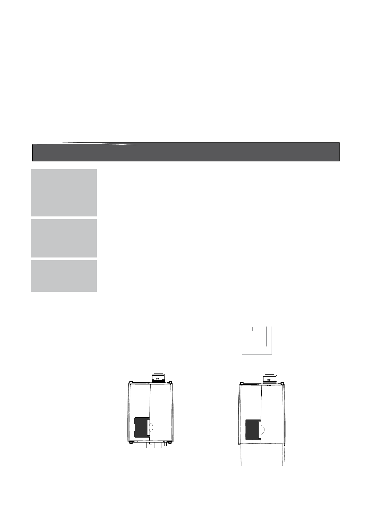
Explanation of the appliance type: Rinnai E110CN
E = Type
110 = Nominal load in (x1000) BTU
C = C = Combi
N = Natural Gas (P = Propane Gas)
Different boilertypes:
Combi boiler with integrated DHW fascility
E75CN E110CN
Installation & Servicing Instructions Rinnai E-Series
E75CP E110CP
8

4 Packaging and transportation
!
4.1 Scope of delivery
The boiler is supplied ready for use.
• Please check if the packaging is intact.
• Check if all the items listed are included in the delivery.
The supply kit is contents:
• Boiler with casing; • Template;
• Automatic air separator (inside the boiler); • Installation instructions;
• Wall mounting suspension bracket; • User manual;
• Bronze adapter ttings; • Service manual;
• 3" PP exhaust adapters (x2); • Outdoor sensor ARV12
• Plumbing kit • 3/4" gas shut off valve
• Fixing material consisting of plugs and screws;
4.2 Transportation
CAUTION
The boiler may be damaged when not secured properly.
- Only transport the boiler using appropriate transportation equipment, such as a
handtruck with a fastening belt or special equipment for maneuvering steps.
- When shipping the boiler must be secured on the transportation equipment to
prevent it from falling off.
- Protect all parts against impacts if they are to be transported.
- Follow the transportation markings on the packaging.
• Packaged boilers must always be lifted and carried by two people, or you must
use a handtruck or special equipment for transport.
Installation & Servicing Instructions Rinnai E-Series
9

5 Installation
y
5.1 Requirements for the installation room
DANGER
!
- The room where the boiler will be installed must always be frost free.
- Do not store or use gasoline or other ammable vapors and liquids in the
vicinity of this or any other appliance.
- Never use or store any chlorinated detergents or halogenated hydrocarbons
(e.g. in spraycans, solvents and detergents, paints, adhesives) in proximity
of the boiler.
- The boiler must be installed in such a way that it is protected from water
(dripping, spraying, rain, etc.) during boiler operation and service (circulator
replacement, condensate trap, control replacement, etc.)
- This boiler is for intended for indoor installations only.
Products to avoid present in boiler room
and/or around combustion air intake
Spray cans containing chloro-/fluorcarbons
Ammonium and/or ammonium solutions
Permanent wave solutions
Chlorinated waxes and/or cleaners
Swimming pool chemicals based on chlorine
Calcium chloride used for thawing
Sodium chloride used for water softening
Refrigerant leaks
Paint or varnish removers
Hydrochloric acid/muriatic acid
Cements and glues
Antistatic fabric softeners used in clothes dryers
Chlorine-type bleaches, detergents, and cleaning solvents
found in household laundry rooms
Adhesives used to fasten building products and
other similar products
Areas likel
Dry cleaning/laundry areas and establishments
Swimming pools
Metal fabrication plants
Beauty shops
Refrigeration repair shops
Photo processing plants
Auto body shops
Plastic manufacturing plants
Furniture refinishing areas and establishments
New building construction
Remodeling areas
Garages with workshops
to have contaminants
Installation & Servicing Instructions Rinnai E-Series
10

5.2 Fitting the boiler
!
!
- Remove the packaging materials.
NOTICE
i
NOTICE
i
CAUTION
- Lay the boiler on its back during unpacking. Remove the casing from the
boiler. This part can be left apart during installation. It must be placed on the
boiler and xed with the screw behind the door and in the 4 quick releases
before the boiler is started up.
Turn the boiler to its side and remove the wall bracket from the back of the
boiler by removing the 2 screws.
The boiler can be mounted practically to any wall with the suspension bracket and the
enclosed mounting equipment.
- The wall must be at and of sufcient strength in order to be able to securely hold
and support the boiler weight with its water content.
- Take note of the necessary space around the boiler for installation of venting
system, pipework and servicing. See drawing on pages 12 to 15.
The location of the boiler can be determined by using the template supplied with the
boiler documentation. Remember to account for the spacing of the plumbing kit.
- Drill the necessary holes using the template
- Install the mounting bracket to the wall using the supplied mounting materials
Lifting and carrying precautions:
To avoid personal injury please follow these recommendations:
- Always lift the boiler with 2 people or use special equipment.
- When lifting the boiler, bend the knees, and keep the back straight and feet
apart.
- Do not lift and twist at the same time.
- Lift and carry the boiler close to the body.
- Wear protective clothing and gloves to protect from any sharp edges.
WARNING
Lift the boiler only by the boiler's rear wall.
- Dispose the packaging materials.
Installation & Servicing Instructions Rinnai E-Series
11
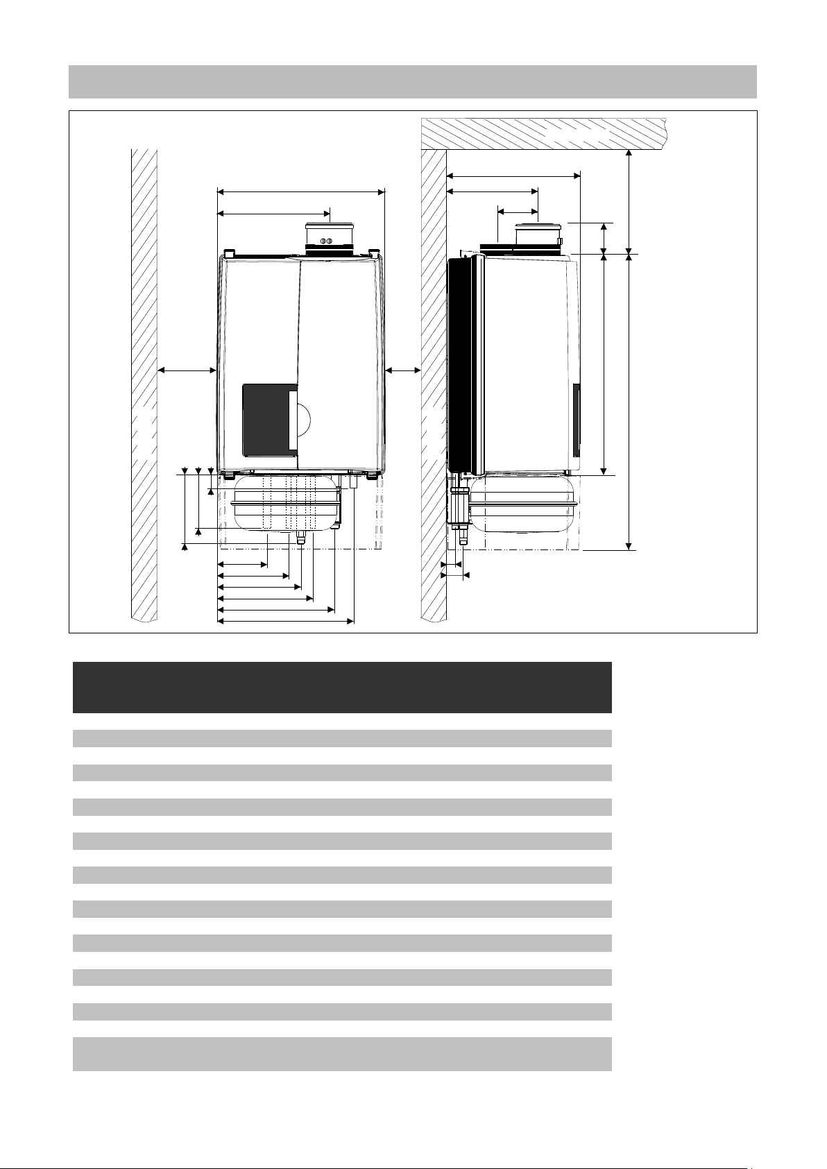
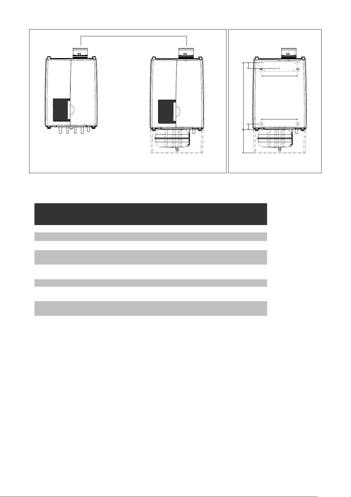
5.3 Dimensions
ceiling
D
C
E
G
F
250mm
Min. 10" /
V
2"
50
wall
Q
R
S
J
P
H
N
K
L
dimensions figure 1
Boiler type
A Height 25.6" / 650 25.6" / 650
B Height with expansion tank 34.3" / 870
C Width 19.7" / 500 19.7" / 500
D Depth 15.6" / 395 15.6" / 395
E Left side / vent 13.2" / 335 13.2" / 335
F Center to center / vent and air supply 4.7" / 120 4.7" / 120
G Back / vent 10.6" / 270 10.6" / 270
H Left side / gas pipe 9.8" / 250 9.8" / 250
J Left side / supply pipe 5.9" / 150 5.9" / 150
K Left side / return pipe 13.8" / 350 13.8" / 350
L Left side / condensate pipe 15.9" / 405 15.9" / 405
N Left side / cold water pipe 11.2" / 285 11.2" / 285
P Left side / hot water pipe 8.5" / 215 8.5" / 215
Q Pipe length of g* 0.7" / 19 8.5" / 215
R Pipe length of c* 1.6" / 40 1.6" / 40
S Pipe length of f, r, k and w* 2" / 50 6.3" / 160
T Back / Center of pipe c, k and w* 1" / 26 1" / 26
U Back / Center of pipe f, g and r* 2" / 50 2" / 50
Pipe length vent co-axial
V
Pipe length vent parallel
dimensions table 1
Installation & Servicing Instructions Rinnai E-Series
0.4"
10
wall
T
U
Combi
E75CN E110CN
E75CP E110CP
inches / mm inches / mm
3.7" / 95
7" / 177
3.7" / 95
7" / 177
B
A
12
Connection for combustion air supply and vent system
f w g k r c
f w g k r c
boiler connections / mounting points figure 2
Boiler type
Combi
E75CN E110CN
E75CP E110CP
Vent system / Combustion air supply
Gas pipe - g
Supply pipe - f
Return pipe - r
Condensate pipe - c
Cold water pipe - k
Hot water pipe - w
connection diameters table 2
80/125mm 80/125mm
3/4"M-NPT 3/4"M-NPT
0.87" x 3/4"M-NPT /
22mm
0.87" x 3/4"M-NPT /
22mm
G3/4"x
3/4"M-NPT
G3/4"x
3/4"M-NPT
0.87" / 22mm 0.87" / 22mm
0.59" x 3/4"M-NPT /
15mm
0.59" x 3/4"M-NPT /
15mm
G1/2"x
3/4"M-NPT
G1/2"x
3/4"M-NPT
Installation & Servicing Instructions Rinnai E-Series
13
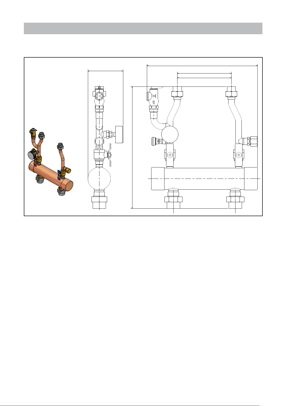
5.3.1 Plumbing Kits
Plumbing Kit 1
Suitable for:
E75CN / E75CP
E110CN / E110CP
Rinnai supplies with each type of boiler a Plumbing kit. Find below the dimensions.
See chapter 6.1 for additional information.
(REF. 16.07)
(REF. 5.12)
(REF. 17.76)
200mm
7.87
1 1/4”1 1/4”
plumbing kit 1 figure 3
Installation & Servicing Instructions Rinnai E-Series
14
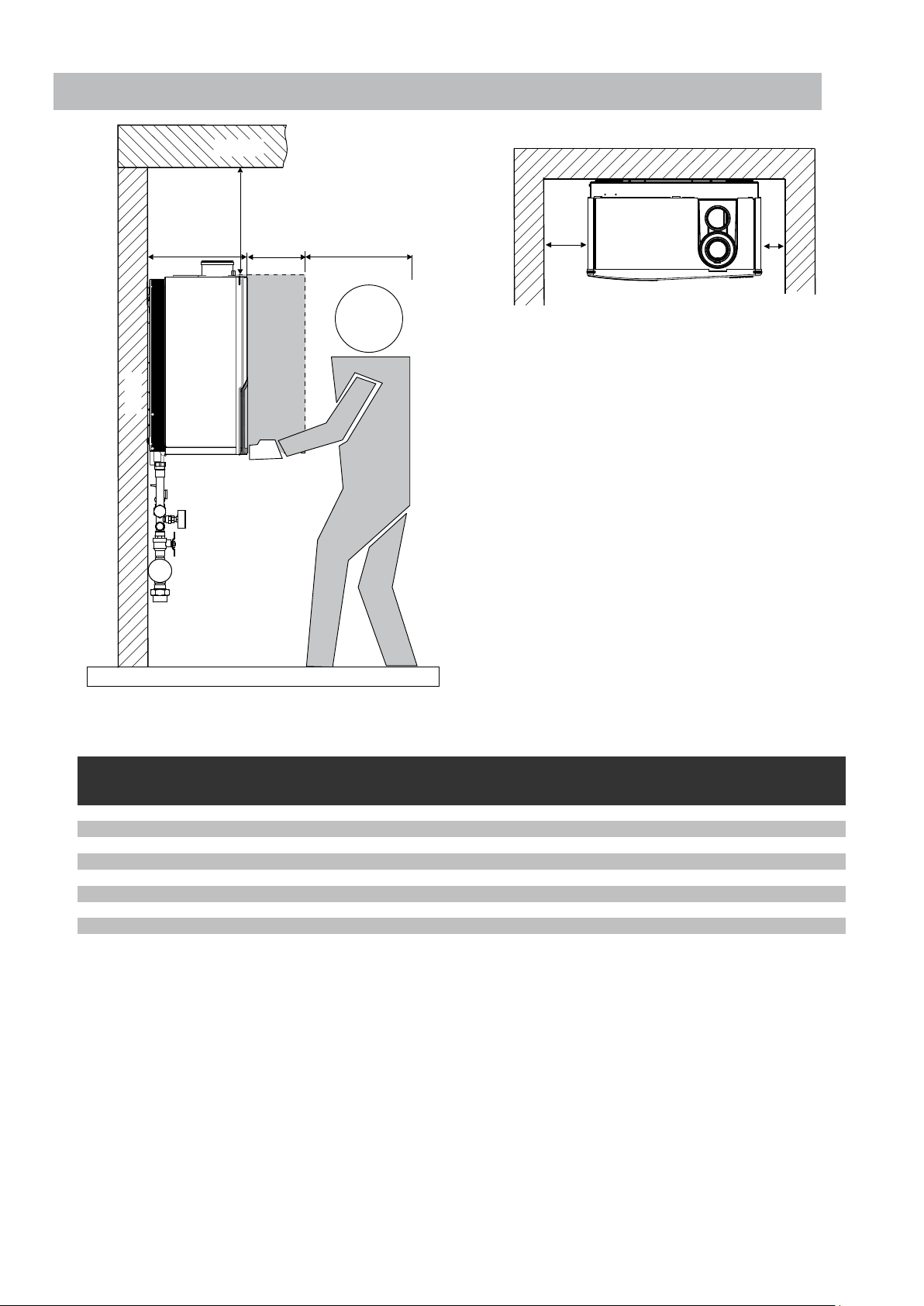
5.3.2 Clearances from boiler
A
A
ceiling
Min. 10" /
250mm
15.7"
400
wall
24"
600
2"
50
0.4"
10
service clearances to the boiler figure 4
Minimum required clearances
to combustibles
All types
inch / mm inch / mm inch / mm
Top of boiler 2" / 50 2" / 50 10" / 250
Back of boiler 0" 0" 0
Front of boiler 6" / 150 6" / 150 24" / 600
Left side of boiler 2" / 50 2" / 50 2" / 50
Right side of boiler 2" / 50 2" / 50 2" / 50
Floor / Ground 12" / 300 12" / 300 30" / 762
Vent 0" 0" 0"
clearances to the boiler table 3
Minimum required clearances
to non-combustibles
ll types
Recommended
service clearances
ll types
For closet installation: clearance is 1” / 25mm from the front.
Low Loss Header
Clearances to combustible and non-Combustible is 0 inch for sides, top, front and oor/ground
Installation & Servicing Instructions Rinnai E-Series
15
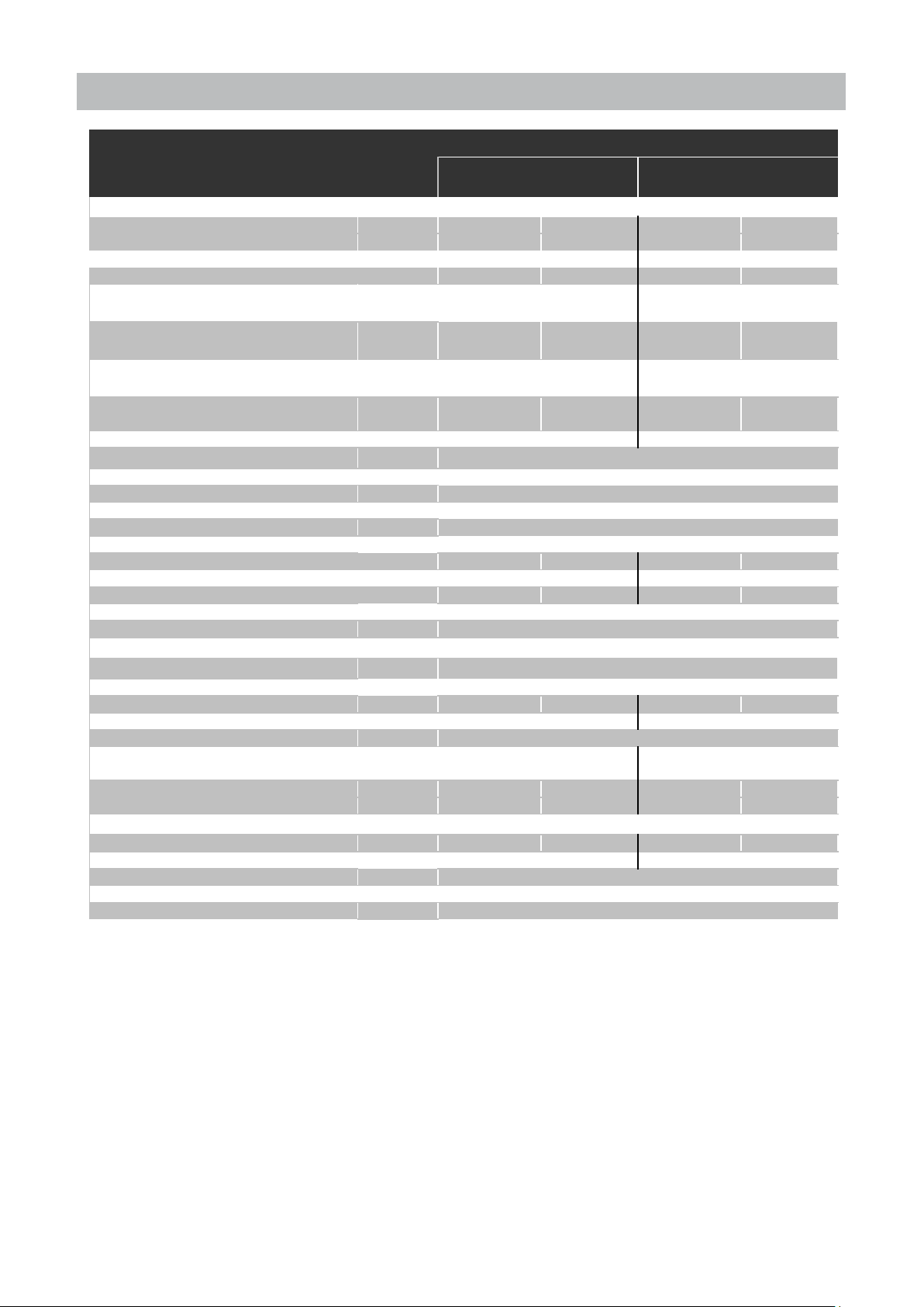
5.4 Technical specications
E-Series
Natural gas
Boiler type E75CN E110CN E75CP E110CP
Input Hs CH BTU/hr 75,000 110,000 75,000 110,000
kW 22 32 22 32
Propane orifice diameter inch / mm n.a. n.a. 0.16" / 4.15 0.20" / 5.2
Display indication at start-up 22.t 32.t 22.tP 32.tP
Q
Output non-condensing CH
n
Q
Output EN677 efficiency CH
n
Q
Output AFUE CH
n
Efficiency at 98.6/86°F (36/30°C) part load,
Hs, EN677 CH
AFUE according IBR
(at full load)
O
2
Electr. power consumption max. W
Electr. power consumption stand by W
Current V/Hz
Fuse rating A
Degree of protection acc. EN 60529
Weight (empty)
Water content CH
Water content DHW
After run time pump CH min
After run time pump DHW min
Water pressure min.-max.
P
MS
P
Water pressure DHW max.
MW
Flow temperature max.
Pump type UPS20-48 UPS20-58 UPS20-48 UPS20-58
Available pump height CH PSI / kPa 3.8 / 26 0.7 / 5 3.8 / 26 0.7 / 5
Approvals
DHW flow (at 50°F)
DHW flow (at 10°C)
DHW flow (at 75°F) gallon/min
DHW flow (at 23.9°C) liter/min
DHW temperature (T
=50°F (10°C)
in
Pressure difference DHW PSI / bar 2.9 / 0.2 4.4 2.9 / 0.2 4.4
Content expansion vessel
Pre-charge pressure expansion vessel PSI / bar
BTU/hr 67,500 98,000 67,500 98,000
kW 19.8 28.8 19.8 28.8
BTU/hr 74,100 108,000 74,100 108,000
kW 21.7 31.7 21.7 31.7
BTU/hr 72,400 105,700 72,400 105,700
kW 21.2 30.7 21.2 30.7
% 98.8 99.0 98.8 99.0
% 96.5 96.1 96.5 96.1
%
4.4 - 4.7
145
14
120Vac/60Hz
5AF & 4AT
IPX4D (IPX0D in case of room air)
lbs / kg
gallon / liter
gallon / liter
91 / 39 101 / 40 91 / 39 101 / 40
0.9 / 3.5 1.3 / 5 0.9 / 3.5 1.3 / 5
0.13 / 0.5 0.18 / 0.7 0.13 / 0.5 0.18 / 0.7
5
1
PSI / bar
PSI / bar
°F / °C
14-43 / 1-3
150 / 10
176 / 80
ASME, CSA
gallon/min 4.6 4.6
liter/min 17.4 17.4
2.1 3.2 2.1 3.2
7.9 12.1 7.9 12.1
°F / °C
gallon / liter
2.1 / 8 3.1 / 12 2.1 / 8 3.1 / 12
176 / 80
14.5 / 1
Propane gas
4.8 - 5.1
CSA number
Technical specifications Table 4
Installation & Servicing Instructions Rinnai E-Series
16
2183087

6 Connecting the boiler
The boiler has the following connection pipes;
- The central heating circuit pipes.
These must connected to the plumbing kit by means of adapter ttings.
See further chapter 6.1;
- The gas supply pipe.
It is provided with a 3/4" male thread into which the tail piece of the gas valve can
be screwed. See further chapter 6.4;
- Cold and hot water pipes for domestic hot water (DHW).
These consist of 3/4" (15 mm) copper pipe and can be connected to the installation
by means of 1/2" M-NPT adapter ttings. See further chapter 6.5;
- The condensation drain pipe.
It consists of an oval 1" (22 mm) plastic pipe. The drain pipe can be connected to
this by means of an open connection. If the open connection is tted in a different
location, then the pipe can be lengthened by means of a 1 1/4" (32 mm) PVC
sleeve. See further chapter 6.6;
- The vent system and air supply system.
It consists of a concentric connection 3"/5" (80/125 mm). The boiler can be converted
to a twin pipe connection that will accept 80mm ue and intake air or with the use
of the included adapters 3” PVC/CPVC ue and intake. See further chapter 6.7.
The pipe to be connected to the boiler must be cleaned before connecting in
i
NOTICE
order to prevent dirt from entering and damaging the boiler.
i
i
i
i
6.1 Central heating system
Connect the central heating system according to its instructions.
The boiler pipes can be connected to the installation by means of compression ttings.
Reducers should be used for connecting to thick-walled pipe (welded or threaded).
When removing the plastic sealing caps from the pipes, dirty testing water
NOTICE
NOTICE
NOTICE
NOTICE
may drain from the boiler.
A Plumbing Kit must be tted to the boiler.
The boiler, when used in connection with a refrigeration system, must
be installed so the chilled medium is piped in parallel with the boiler with
appropriate valves to prevent the chilled medium from entering the boiler.
The boiler piping system of a hot water boiler connected to heating coils
located in air handling units where they may be exposed to refrigerated air
circulation must be equipped with ow control valves or other automatic
means to prevent gravity circulation of the boiler water during the cooling
cycle.
Installation & Servicing Instructions Rinnai E-Series
17
i
i
6.1.1 Plumbing Kit installation
Rinnai supplies specic Plumbing Kits with each boiler type, which must be tted
NOTICE
NOTICE
directly underneath the boiler on the supply and return pipe. Use of the Rinnai boiler
without the plumbing kit will result in the void of warranty.
To protect the entire heating system we recommend installing a dirt particle
trap in the return circuit. When the boiler is installed to an existing heating
system this trap is required. Use of a Y strainer is not permitted as substitute
for a dirt trap.
- Install shut-off valves immediately before and after the dirt particle lter to allow
the lter to be cleaned.
- Position 3 (gure 6) is a garden house thread boiler drain, that can be used to
drain the boiler or add water tratment additives to the system, such as inhibitors
or glycol.
- Position 4 (gure 6) is the supply connectionfor an idirect tank when used with the
optinal 3-way valve kit.
- For information on locating the expansion tank and system ll, please see the
Rinnai Boiler Applications Manual.
Thoroughly ush all pipes and radiators. We recommend the use of a Rinnai
approved system cleaner. Refer to the Rinnai Boiler Applications Manual for
an approved list of Rinnai system cleaners.
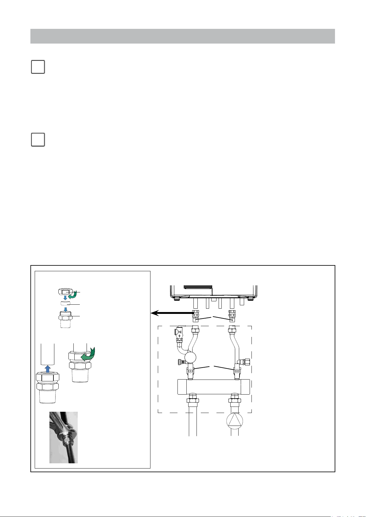
Compression fittings.
Parts:
1. Nut
2. Ferrule
3. Fitting
Fitting instructions:
1. Push the com ple te
21
2. Turn the nut handtight
- Refer to the installation template and chapter 5.3 for the pipe connection
dimensions.
- Fit the bronze adapter ttings, supplied with the boiler (g. 5, pos. 4) rst to the
Plumbing Kit and then to the boiler.
- Connect the expansion tank to the system. See chapter 6.2.
- Connect the pipes so that they are free from strain.
4
1
fitting over the pipe as
far as possible. Ferrule
sh ould be ov er the
pipe completely.
clockwise.
2
3
5
1. Plumbing kit
2. Safety valve
3. Filling connection
4. Bronze adapter ttings
5. Service valves
6. Flow 1 1/4"
7. Return 1 1/4"
8. External pump
6
7
3
3. Use 2 wrenches, one
to hold the fitting on
its place, the other
fo r tighten the n ut
clockwise in 3/4 turn.
Plumbing Kit installation g. 5
Installation & Servicing Instructions Rinnai E-Series
8
18
i
i
NOTICE
NOTICE
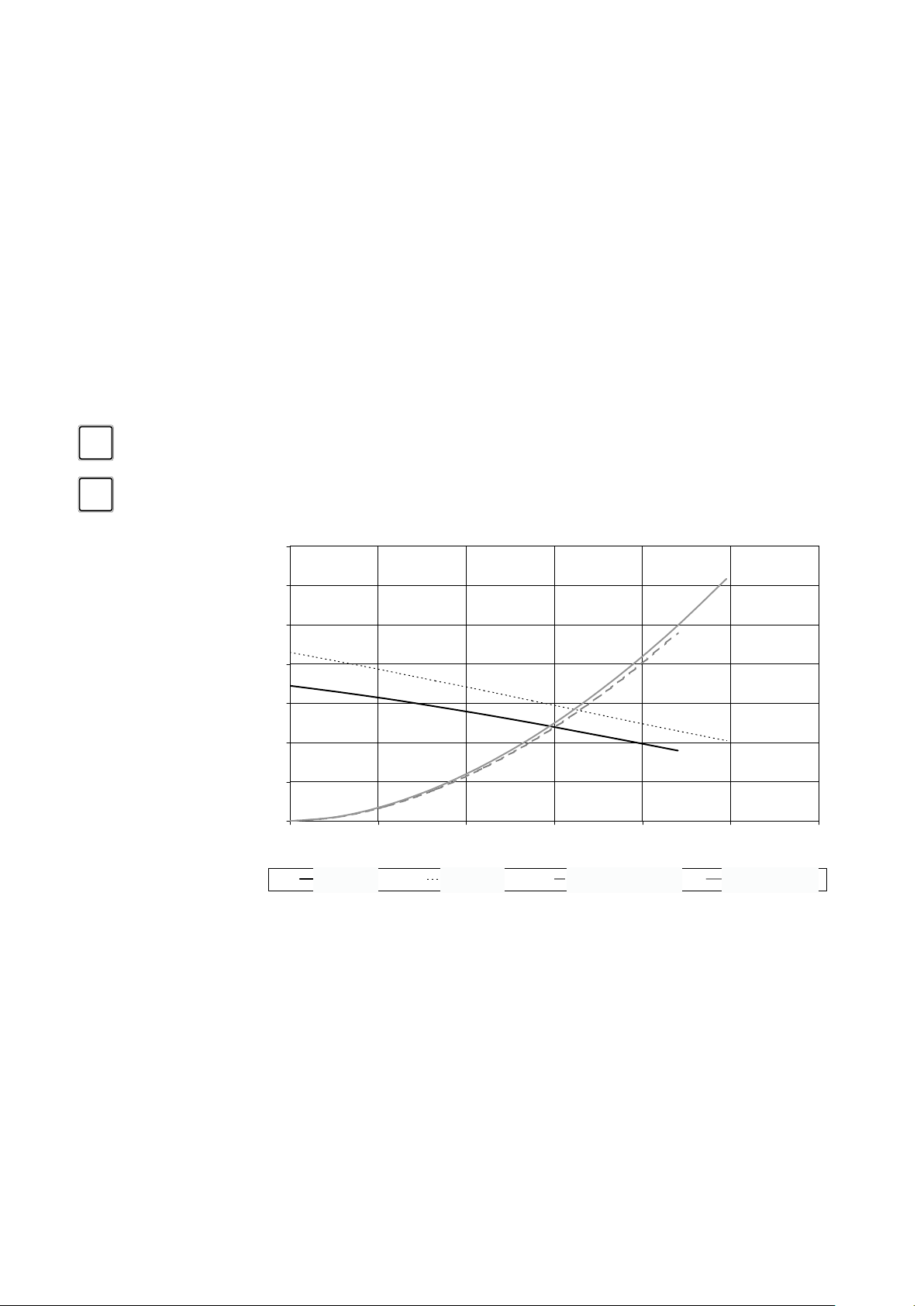
The boiler has a self-adjusting and self-protecting control system for the load and the
pump capacity. By this means the temperature difference between the supply and return
water is checked and controlled.
If the installation resistance is over the stated value; the load will be adjusted until
an acceptable temperature difference between supply and return water has been
obtained. If, after this, the temperature difference is still not acceptable then the boiler
will switch off and wait until an acceptable temperature has arisen.
If an unacceptable temperature is detected, the control will repeatedly try to achieve
water ow over the boiler. If not the boiler will switch off.
The electrical side of an external circulation pump (g. 6, pos. 8) can be connected
to the Control Tower. This pump thus switches simultaneously to the boiler pump.
The maximum absorbed current consumption of the external circulation pump may
not exceed 120V, 2 Amp. If a pump with a larger current draw is required an isolation
relay must be used. See the Rinnai Boiler Applications Manual for further information.
The extra external pump must be selected according the installation resistance and
required ow.
As standard the boiler is provided with a water lter in the return pipe of the boiler, so
that debris of the central heating water is prevented from affecting the boiler.
When using more than one boiler in an installation please refer to the cascade
installation instructions.
The boiler is designed to be used on pressurized heating systems only.
14
12
10
8
PSI
6
4
2
0
0 2 4 6 8 10 12
UPS 20-48 UPS 20-58 Resistance OSS1 Resistance OSS2
25%
pump index lines graph 1
UPS 20-58
100%
Q [gallons/min]
Resistance E75CUPS 20-48
Resistance E110C
32.3
27.7
23.0
18.5
13.8
Feet of head
9.2
4.6
0
Installation & Servicing Instructions Rinnai E-Series
19

6.1.2 Safety valve
i
i
NOTICE
An ASME 30 psi pressure relief valve is installed on the plumbing kit included
with the boiler.
6.1.3 Low water cut off
The Rinnai E boiler has a factory installed pressure switch type Low Water Cut
NOTICE
Off (LWCO). Check your local codes to see if a Low Water Cut Off is required
(LWCO) and if this device conforms to local code. See the Rinnai Boiler
Applications Manual for further information.
The Low water cut off is not serviceable.
6.2 Expansion tank
The E-Series boilers are equiped with an internal expansion tank.
The tank of the E75CN and E75CP is positioned inside the boiler casing. This
expansion tank has a pre-charge pressure of 14.5 PSI / 1 Bar and a capacity of 2.1
gallon / 8 litres.
The tank of the E110CN and E110CP is positioned directly beneath the boiler and
together with the casing forms a single entity with the boiler.
The casing can be removed by pulling forwards. The expansion tank has a pre-charge
pressure of 14.5 PSI / 1 Bar and a capacity of 3.1 gallon / 12 litres.
If a larger capacity expansion tank is needed for the installation a standard expansion
vessel should be tted additionally.
i
NOTICE
In that case choose an expansion tank volume, of which the summary is geared to
the installation’s water capacity. The pre-charge pressure depends on the installation
height above the expansion tank. Fit the expansion tank into the return pipe as close
as possible to the boiler. The extra expansion tank should be sourced locally. Please
refer to the expansion tank manufacturer for further information.
Fill the expansion tank to a minimum of 14.5 psi.
Installation & Servicing Instructions Rinnai E-Series
20

6.3 Underoor heating system (plastic pipes)
!
!
!
When using oxygen-permeable pipes, e. g. for underoor heating systems, the system
must be separated using plate heat exchangers.
NOTICE
i
DANGER
WARNING
DANGER
No recourse can be made to the terms of the warranty in the event of failure
to regard the regulations pertaining to plastic underoor heating pipes.
6.4 Gas supply connection
Only work on gas lines if you are licensed for such work.
If these instructions are not followed exactly, a re or explosion may result
causing property damage, personal injury or death.
Rinnai wall mounted boilers are built to run on Natural Gas or Propane Gas.
The gas type the boiler is suitable for is indicated on the packaging and on
the boiler by a blue label with Natural Gas or a green label with Propane Gas
and on the identication plate on the boiler.
First check the identication plate on the boiler for the suitable gas type.
Do not use the boiler for another type of gas than indicated on the
identication plate of the boiler. This will cause improper functioning and can
damage the boiler.
Natural gas: resume with chapter 6.4.1
Propane gas: resume with chapter 6.4.2
Installation & Servicing Instructions Rinnai E-Series
21
6.4.1. Gas connection with natural gas
!
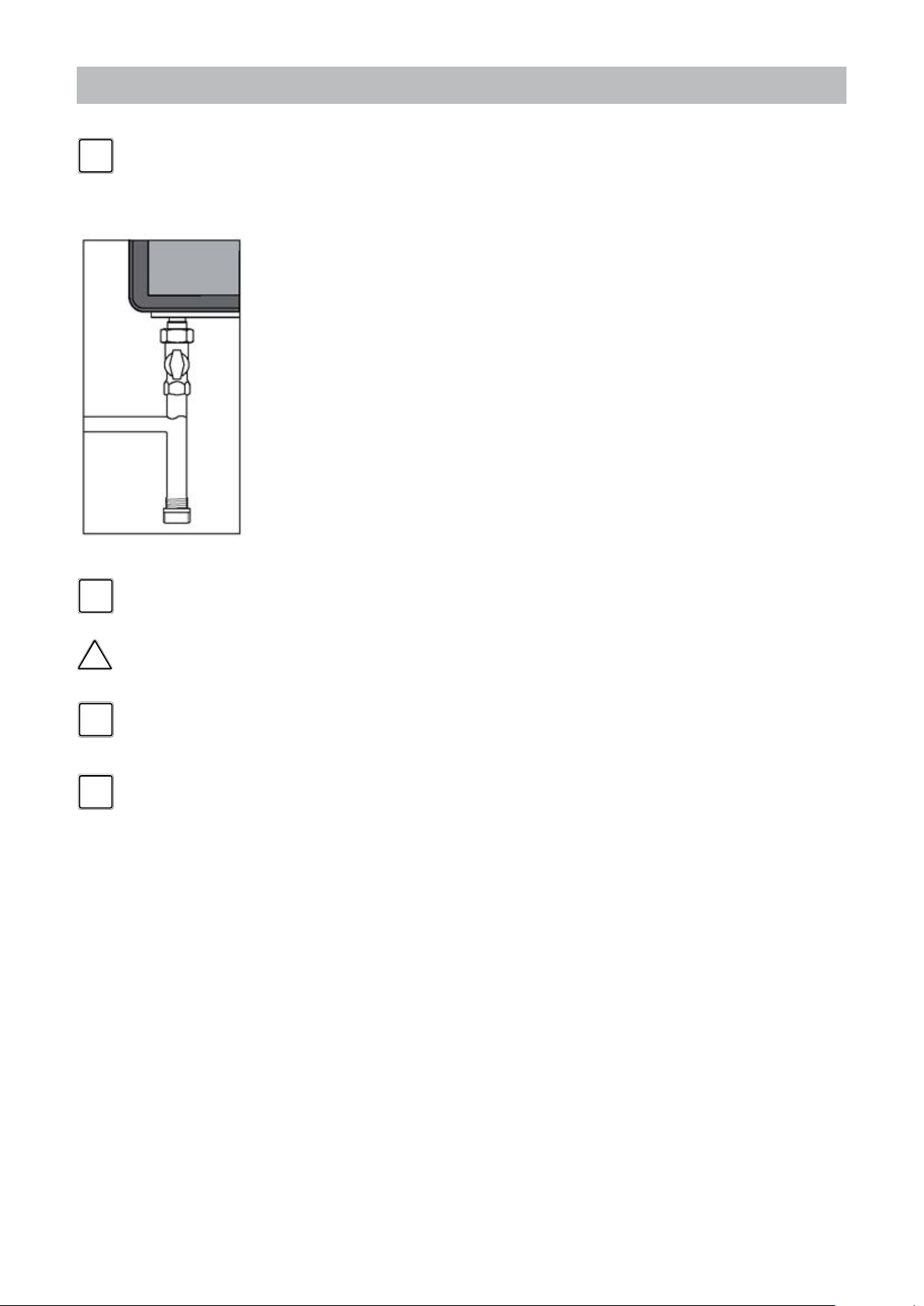
NOTICE
i
Sediment trap gure 7
The gas supply connection must comply with local regulations or, if such
regulations do not exist, with the National Fuel Gas Code, ANSI Z 223.1.
For Canada, the gas connection must comply with local regulations or, if
such regulations do not exist, with the CAN/CSA B149.1, Natural Gas and
Propane Installation Code.
Pipe sizing for natural gas
Contact gas supplier to size the gas supply line and meter.
Gas piping
A sediment trap must be installed upstream of the gas controls.
The boiler gas pipe is equiped with external 3/4" M-NPT thread, onto which the tail
piece of the gas shut off valve can be connected. Use appropiate sealing.
The connection to the boiler must include a suitable method of disconnection and a gas
control valve must be installed adjacent to the boiler for isolation purposes. The nominal
inlet gas pressure measured at the boiler should be 7" W.C. (18 mbar) for Natural gas
(Gas A). Maximum pressure with no ow (lockup) or with the boiler running is 10.5
inches W.C. Minimum pressure with the gas owing (verify during boiler startup) is
5.0 inches W.C.
The gas pipe must be tted to the gas valve free from any strain.
NOTICE
i
DANGER
NOTICE
i
NOTICE
i
Make sure that the gas pipe system does not contain dirt, particularly with
new pipes.
Always check the safety of the gas pipe system by means of a bubble test
using leak-search spray.
The boiler and its individual shut off valve must be disconnected from the
gas supply piping system during any pressure testing of that system at test
pressures in excess of 1/2 PSI (3.5kPa).
The boiler must be isolated from the gas supply piping system by closing its
individual manual shutoff valve during any pressure testing of the gas supply
piping system at test pressures equal to or less than 1/2 PSI (3.5 kPa).
Installation & Servicing Instructions Rinnai E-Series
22
6.4.2 Gas connection with propane gas
!
!
NOTICE
i
DANGER
The gas supply connection must comply with local regulations or, if such
regulations do not exist, with the National Fuel Gas Code, ANSI Z 223.1.
For Canada, the gas connection must comply with local regulations or, if
such regulations do not exist, with the CAN/CSA B149.1, Natural Gas and
Propane Installation Code.
Pipe sizing for propane gas
- Contact gas supplier to size pipes, tanks, and 100% lockup gas pressure
regulator.
Propane Supply Pressure Requirements
- Adjust propane supply regulator provided by the gas supplier for 14 inches W.C.
maximum pressure.
- Pressure required at gas valve inlet pressure port:
- Maximum 14 inches W.C. with no ow (lockup) or with boiler running.
- Minimum 8 inches W.C. with gas owing (verify during boiler startup).
Ensure that the high gas pressure regulator is installed at least 6 to 10 feet
upstream of the boiler.
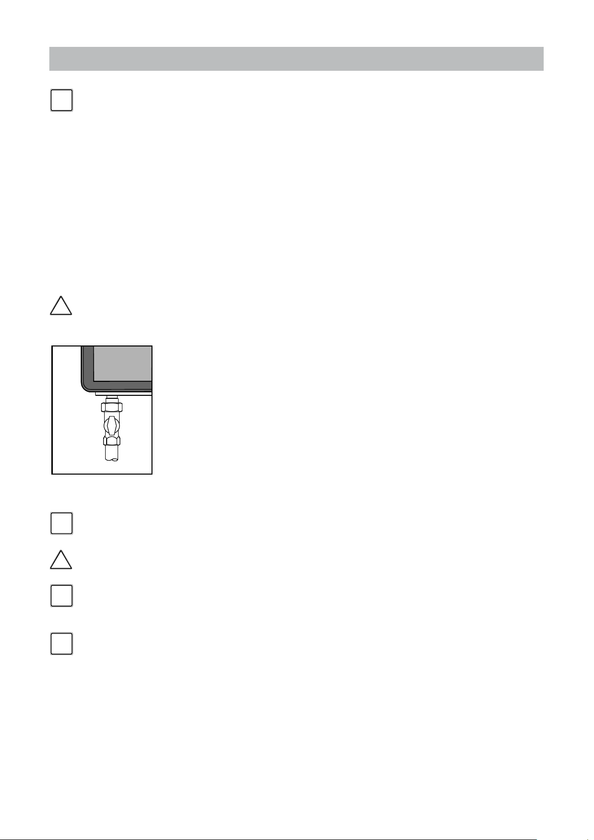
Gas piping
- Use a gas shut off valve compatible with propane gases.
- A sediment trap must be provide upstream of the gas controls.
The boiler pipe is equiped with external 3/4" M-NPT thread, onto which the tail piece
of the gas shut off valve can be screwed. Use appropriate sealing.
Gas shut off valve onto boiler
gure 7
NOTICE
i
DANGER
NOTICE
i
NOTICE
i
The connection to the boiler must include a suitable method of disconnection.
A gas control valve must be installed adjacent to the boiler for isolation purposes. The
nominal inlet working gas pressure measured at the boiler should be 12 inch W.C.
(30mbar) for Propane gas (Gas E).
The gas pipe must be tted to the gas valve free from any strain.
Make sure that the gas pipe system does not contain dirt, particularly with
new pipes.
Always check the safety of the gas pipe system by means of a bubble test
using leak-search spray.
The boiler and its individual shut off valve must be disconnected from the
gas supply piping system during any pressure testing of that system at test
pressures in excess of 1/2 PSI (3.5kPa).
The boiler must be isolated from the gas supply piping system by closing its
individual manual shutoff valve during any pressure testing of the gas supply
piping system at test pressures equal to or less than 1/2 PSI (3.5 kPa).
Installation & Servicing Instructions Rinnai E-Series
23
6.5 Hot water supply
Connection of the drinking water installation should be performed according to the
national secondary drinking water regulations.
DANGER
!
NOTICE
i
Do NOT use toxic chemicals, such as are used for boiler treatment in potable
water heating systems used for space heating.
The sanitary water pipes can be connected to the installation by use of adapter
ttings. The cold water inlet on the Combi boilers must be equiped with the following
components (counted in the water ow direction):
Flow regulator valve (supplied), Safety group, Expansion vessel 87 PSI / 6bar (potable
water, blue).
The 3/4" NPT adapter tting with ow reducing valve must be tted in the cold water
connection.
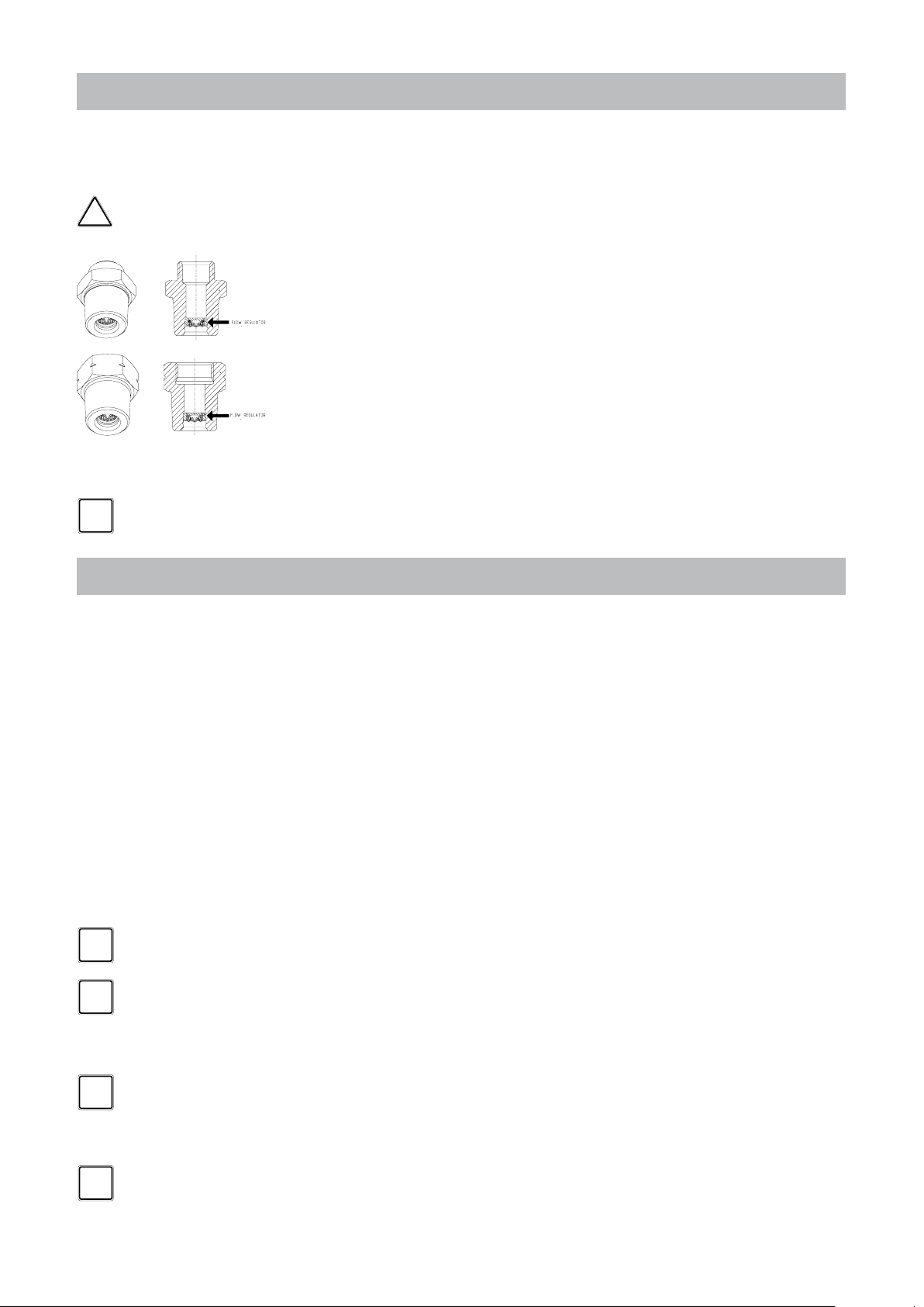
A ow regulator valve is supplied with the boiler in a 3/4"NPT adapter tting. The
ow regulator valve ensures that a quantity of water is supplied which has a outlet
temperature of 120°F (assuming a cold water temperature of 45°F). The quantity of
water is virtually unaffected by the water pressure.
When there is a water pressure lower than 22PSI / 1.5 bar it is advisable to
remove the inside mechanism of the ow reducing valve.
6.6 Condensate drain pipe
This boiler produces condensate. Condensate must be drained otherwise the boiler
will not function and can cause property damage.
i
i
i
NOTICE
NOTICE
NOTICE
The condensation drain pipe should be connected to a drain in the building by means
of an open connection. By this means the possibility of drain gases effecting the boiler
is prevented. The drain connection should have a minimum diameter of 1.3" / 32mm.
Install the condensation drain pipe according to the applicable rules and
regulations.
If the condensate outlet of the boiler is lower than the public sewage system a
condensate pump must be used.
The condensate produced by the boiler has a pH value between 3 and 4.
Install a neutralization unit if required by the local code. It is recommended, but not
required to install a condensate neutralizer.
Do not drain the condensation water to the external rain gutter because of
the danger of freezing and blockage of the drain.
Before putting the boiler into operation ll the condensate trap with 1.27
cups / 300 ml of water. If the boiler will be installed in a high temperature
installation such as baseboard, then ll the condensate trap with mineral oil
instead of water.
Use materials approved by the authority having jurisdiction. In absence of such
authority, PVC and CPVC pipe must comply with ASTM D1785, F441 or D2665.
Cement and primer must comply with ASTM D2564 or F493.
For Canada, use CSA or ULC certied PVC or CPVC pipe, ttings and cement.
NOTICE
i
Installation & Servicing Instructions Rinnai E-Series
Periodic cleaning of the condensate disposal system must be carried out. See
the Rinnai Boiler Application Manual for further information and for a piping
diagram for the condensate.
24

6.7 Vent system and air supply system
Provisions for combustion and ventilation air must be made in accordance with section,
Air for Combustion and Ventilation of the National Flue Gas Code, ANSI Z223.1,
or Sections 7.2, 7.3 of 7.4 of CAN/CGA B149.1, Installation Codes, or applicable
provisions of the local building codes.
- Do not store chemicals near the boiler or in rooms where the air is being supplied
to the boiler. See the list on page 10.
- Do not allow the ue gases of other appliances to enter the boiler.
- Keep cabinet free of moisture
i
NOTICE
In the event that the system has actuated to shut off the main burner gas,
do not attempt to place the boiler in operation. Contact a qualied service
agency.
6.7.1 Intake / Exhaust Guidelines
Refer to the specic instructions on your vent product for additional installation
requirements.
• You must use vent components that are certied and listed with this model.
• Do not combine vent components from different manufacturers.
• Venting should be as direct as possible with a minimum number of pipe ttings.
• Avoid dips or sags in horizontal vent runs by installing supports per the vent
manufacturer’s instructions.
• Support horizontal vent runs every four feet and all vertical vent runs every six
feet or in accordance with local codes.
• Vent diameter must not be reduced.
• The boiler is unsuitable to install on a common vent installation, see also chapter 19.
• Do not connect the venting system with an existing vent or chimney.
• Do not common vent with the vent pipe of any other water heater or appliance.
• Vent connections must be rmly pressed together so that the gaskets form an air
tight seal.
• Refer to the instructions of the vent system manufacturer for component assembly
instructions.
• If the vent system is to be enclosed, it is suggested that the design of the enclosure
shall permit inspection of the vent system. The design of such enclosure shall be
deemed acceptable by the installer or the local inspector.
i
NOTICE
If it becomes necessary to access an enclosed vent system for service or
repairs, Rinnai is not responsible for any costs or difculties in accessing
the vent system. Warranty does not cover obtaining access to an enclosed
vent system.
Installation & Servicing Instructions Rinnai E-Series
25
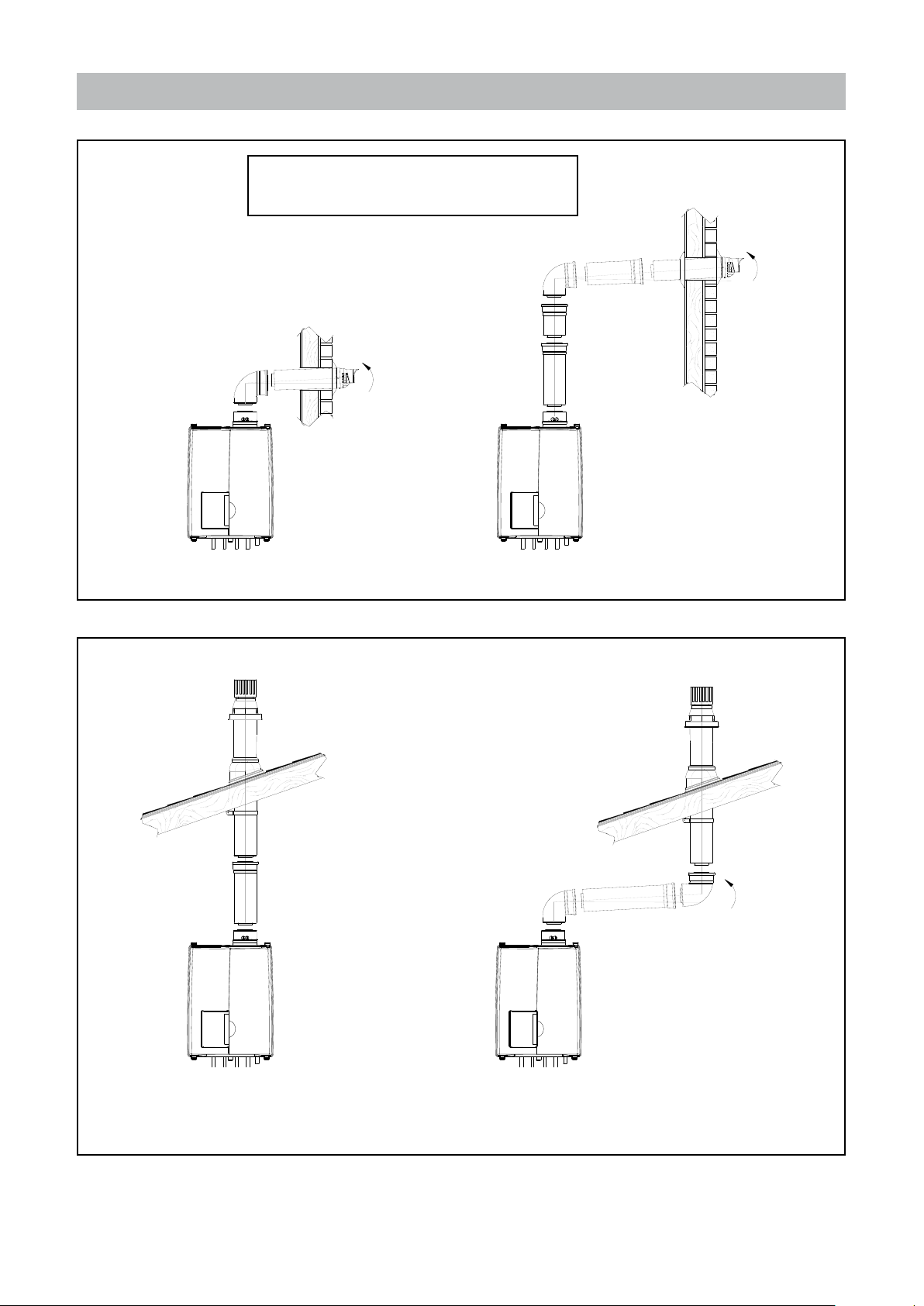
6.7.2a Examples vent and air supply systems (concentric)
Wall thickness for vent termination installation:
Minimum: 100mm / 4”
Maximum: 508mm / 20”
Short termination with wall terminal
figure 9A
Examples wall terminals
Termination with wall terminal on higher level
figure 9B
Short termination with roof terminal
figure 10A
Examples roof terminals
Termination with roof terminal and bends
figure 10B
Installation & Servicing Instructions Rinnai E-Series
26
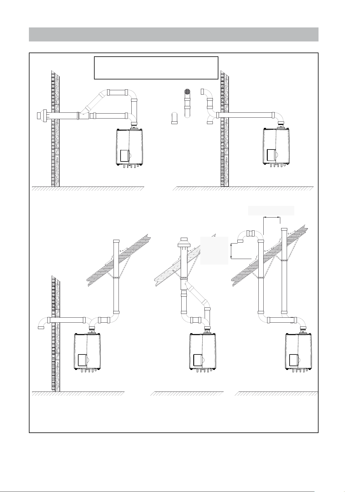
6.7.2 b Examples vent and air supply systems (parallel)
Wall thickness for vent termination installation:
Minimum: 100mm / 4”
Maximum: 508mm / 20”
Horizontal with concentric termination figure 11A
Examples sealed combustions
Horizontal with parallel termination figure 11B
10" MINIMUM INSIDE EDGE
T`O INSIDE EDGE
Vertical vent and horizontal air intake
figure 11C
12" OVER
MAXIMUM
SNOW LEVEL
OR 24"
WHICHEVER IS
GREATER
Vertical with concentric termination
figure 11D
Vertical with parallel termination
figure 11E
Installation & Servicing Instructions Rinnai E-Series
27
6.7.3 Installation of the vent system
i
i
NOTICE
NOTICE
Consult local and state codes pertaining to special building code and re department
requirements. Adhere to national code requirements.
Follow the listed maximum length of vent systems, which are boiler output dependent.
The maximum permissible lengths are listed in table 9, chapter 6.7.6.
Decide how to install the exhaust and air intake system. You can choose between:
- Concentric system (see page 26)
The concentric connection is provided standard initially.
The boiler concentric connection diameter is 3"/5" (80/125 mm), to which the venting and air
supply system can be tted, with or without elbow pieces. The maximum permissible pipe length
is displayed in table 9, chapter 6.7.6.
- Parallel system (see page 27)
The boiler can be converted to a parallel system with supplied adapters.
It is possible to use a parallel pipe connection of 2x 3". In this case a seperate supplied kit, with
2 vent adapters 3" (ø80mm), cover 5" (ø125mm), vent exhaust pipe and gaskets should be
tted instead of the concentric vent adapter on top of the boiler. See gure 12 for installation.
The maximum permissible pipe length is set out in table 9, chapter 6.7.6.
- Room Air System (outdoor combustion air)
The boiler can use room air for combustion. If this option is selected the boiler must rst be
converted to the Parallel system. A single exhaust pipe can then be tted. It is required to use
a room air lter when using indoor air for combustion. The maximum permissible pipe length
is set out in table 9, chapter 6.7.6.
NOTICE
i
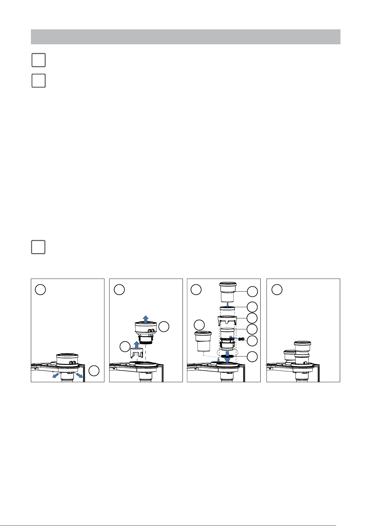
A B C D
boiler conversion from concentric to parallel gure 12
A. 1. Push the 2 clips slightly outwards
B. 2. Pull the concentric adaptor out of the boiler
3. Press the cover in the connection at the back from inside out
C. 4. Push the 3" adapter into the connection at the back of the boiler (= air intake)
5. Pull the rubber seal around the bottom of the exhaust connector
6. Push the exhaust connector in the boiler, in the boiler exhaust pipe until 'CLICK'
7. Push the 5" cover over the exhaust connector in the 5" opening until 'CLICK'
8. Push the rubber plug in open position in the O2 measuring opening and close the stop.
9. Push the gasket around the top of the exhaust connector
10. Push the 3" exhaust adaptor in the exhaust connector.
D. Connect the parallel vent system.
We advise to install a vent system out of the venting system program supplied by
Rinnai (See chapter 19 Parts list Vent system). For further information about the
available components of the venting and air supply system we recommend you
consult Rinnai and the Installation instructions and parts list documentation.
10
9
7
2
3
1
4
6
8
5
Installation & Servicing Instructions Rinnai E-Series
28
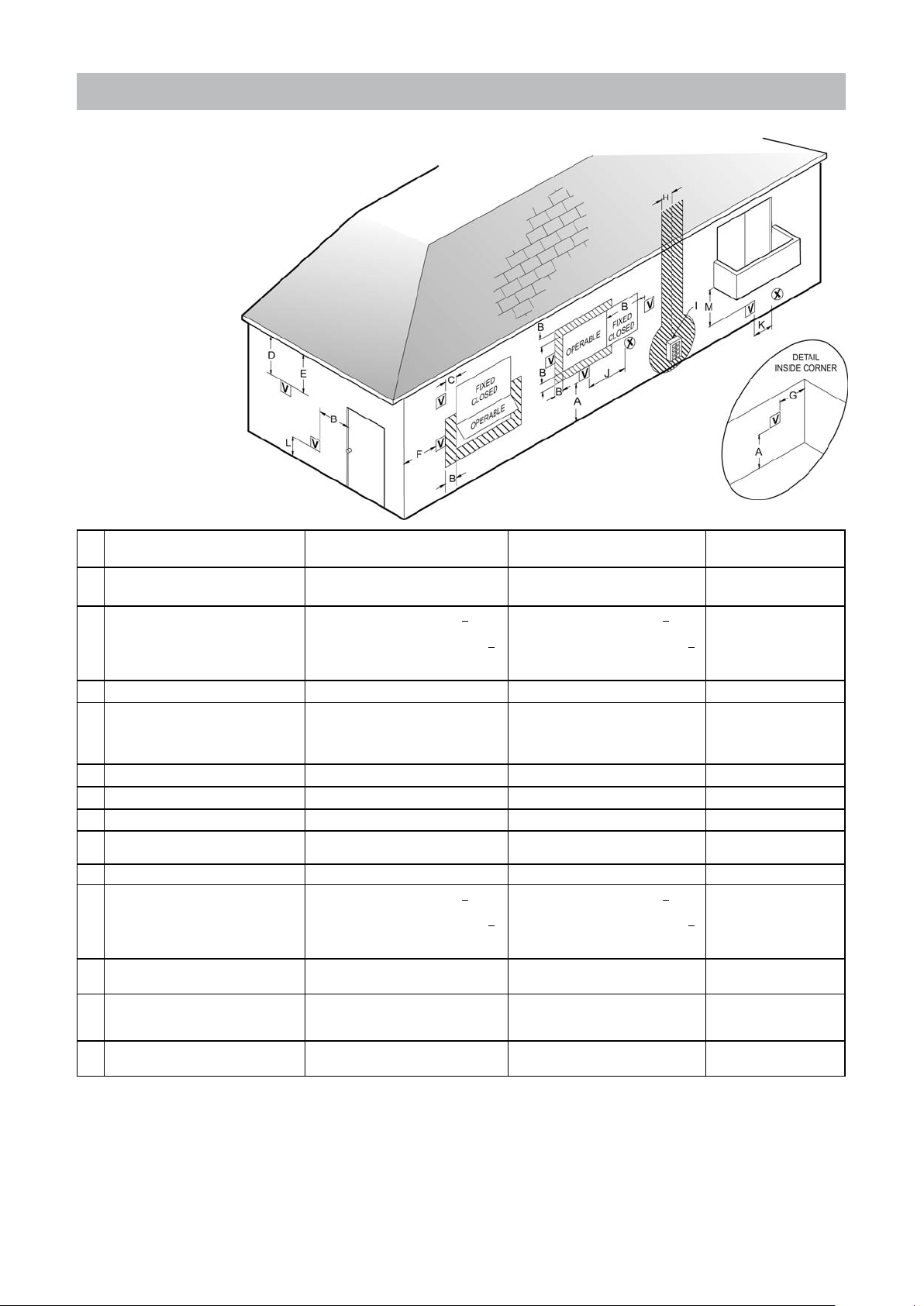
6.7.4 Recommended vent/air intake terminal position
Terminals should be positioned as to avoid products of combustion entering openings into buildings or other vents.
Maintain 12” of clearance
above the highest
anticipated snow level
or grade or, whichever is
greater. Please refer to
your local codes for the
snow level in your area.
Terminal positions figure 14
Ref Description Canadian Installations - Direct Vent
A Clearance above grade, veranda, porch,
deck, or balcony
B Clearance to window or door that may
be opened
C Clearance to permanently closed window * * *
D Vertical clearance to ventilated sof-
t, located above the terminal within a
horizontal distance of 2 feet (61 cm) from
the center line of the terminal
E Clearance to unventilated soft * * *
F Clearance to outside corner * * *
G Clearance to inside corner * * *
H Clearance to each side of center line ex-
tended above meter/regulator assembly
I Clearance to service regulator vent outlet 36 inches (91 cm) * *
J Clearance to nonmechanical air supply
inlet to building or the combustion air inlet
to any other appliance
K Clearance to a mechanical air supply
inlet
L Clearance above paved sidewalk or
paved driveway located on public
property
M Clearance under veranda, porch, deck,
or balcony
6 inches (15 cm) for appliances < 10,000
100,000 Btuh (30 kW), 36 inches (91 cm)
3 feet (91 cm) within a height 15 feet (4.5
6 inches (15 cm) for appliances < 10,000
100,000 Btuh (30 kW), 36 inches (91 cm)
and non Direct Vent
12 inches (30 cm) 12 inches (30 cm) 12 inches (30 cm)
Btuh (3 kW), 12 inches (30 cm) for ap-
pliances > 10,000 Btuh (3 kW) and <
for appliances > 100,000 Btuh (30 kW)
* * *
m) above the meter/regulator assembly
Btuh (3 kW), 12 inches (30 cm) for ap-
pliances > 10,000 Btuh (3 kW) and <
for appliances > 100,000 Btuh (30 kW)
6 feet (1.83 m) 3 feet (91 cm) above if within 10 feet (3
7 feet (2.13 m) [1] * 7 feet (2.13 m)
12 inches (30 cm) [2] * *
US Installations Direct Vent US Installations
6 inches (15 cm) for appliances < 10,000
Btuh (3 kW), 9 inches (30 cm) for appliances > 10,000 Btuh (3 kW) and <
50,000 Btuh (30 kW), 12 inches (91 cm)
for appliances > 50,000 Btuh (30 kW)
* *
6 inches (15 cm) for appliances < 10,000
Btuh (3 kW), 9 inches (30 cm) for appliances > 10,000 Btuh (3 kW) and <
50,000 Btuh (30 kW), 12 inches (91 cm)
for appliances > 50,000 Btuh (30 kW)
m) horizontally
non Direct Vent
4 feet (1.2 m) below or to
side of opening; 1 foot (300
mm) above opening
4 feet (1.2 m) below or to
side of opening; 1 foot (300
mm) above opening
3 feet (91 cm) above if wit-
hin 10 feet (3 m) horizontally
[1] A vent shall not terminate directly above a sidewalk or paved driveway that is located between two single family dwellings and serves
both dwellings.
[2] Permitted only if veranda, porch, deck, or balcony is fully open on a minimum of two sides beneath the oor.
* For clearances not specied in ANSI Z223.1/NFPA 54 or CSA B149.1, clearances are in accordance with local installation codes and the
requirements of the gas supplier.
clearances of venting system terminals table 6
Installation & Servicing Instructions Rinnai E-Series
29
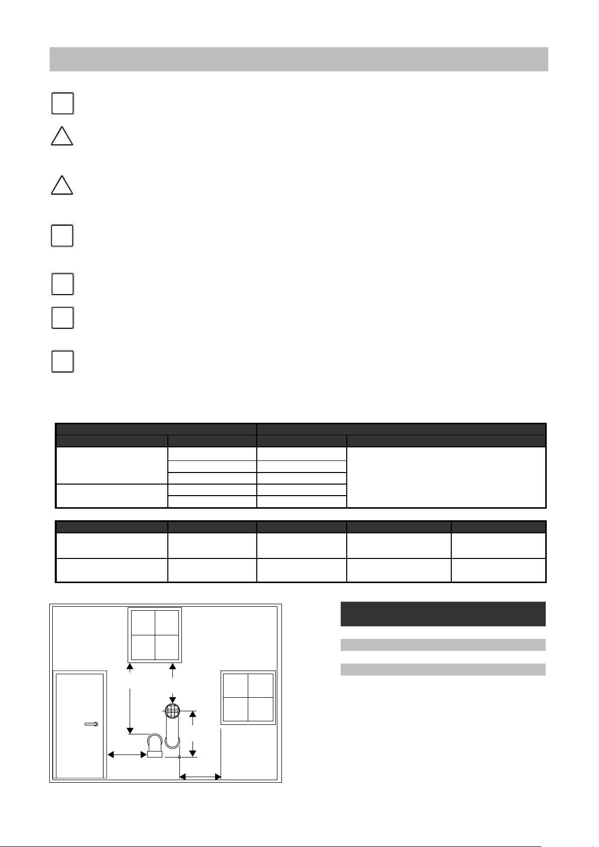
6.7.4 Recommended vent/air intake terminal position
p
r
NOTICE
i
CAUTION
!
CAUTION
!
NOTICE
i
NOTICE
i
NOTICE
i
NOTICE
i
Terminals should be positioned as to avoid products of combustion entering
openings into buildings or other vents.
Maintain 12” of clearance above the highest anticipated snow level or grade
or, whichever is greater. Please refer to your local codes for the snow level in
your area.
The termination shall be at least 4 feet (1,220 mm) for the US and 6 feet (1,830
mm) for Canada distance from electric meters, gas meters, regulators and
relief equipment. (for room air application only)
Horizontal vent systems should always be installed sloping towards the
boiler (min. 21 mm/m, 1/4 “/ feet), in order to avoid condensate retaining in
the vent system. With the condensate running back to the boiler the risk of
ice forming at the terminal is reduced.
The whole route of the vent system must be installed upwards, never
downwards, completely nor partly.
Place pipe supports every 4 feet (1219 mm) of horizontal run, beginning with
the support near the boiler to prevent movement in ttings and allow boiler
to be free from any strain or weight on boiler or ttings.
The terminal should be located where dispersal of combustion products is
not impeded and with due regard for the damage or discolouration that might
occur to building products in the vicinity (see g 14 and 15).
Approval Codes for Installation
Item Description Flue Material United States
Plastic Vent and/or air
pipes and fittings
Plastic Pipe cement and
rime
Item Description Flue Material Manufacturer US/CAN Flue system
Stainless steel vent
systems AL29-4C Heat Fab
Plastic Vent and/or air
pipes and fittings
Approval codes for installation of venting system table 7
12" (300 mm)
minimum
EXHAUST
PVC Schedule 40 ANSI/ASTM D1785
PVC - DWV ANSI/ASTM D2665
CPVC Schedule 40 ANSI/ASTM F441
PVC ANSI/ASTM D2564
CPVC ANSI/ASTM F493
PPS Ubbink
12" (300 mm)
minimum
concentric
UL1738 twin pipe
Fittings or Piping Equivalent
45 degree elbow 3 0.91
90 degree elbow 6 1.83
plastic pipe per foot 1 0.30
concentric vent kit 3 0.91
Equivalent friction loss of PVC/CPVC table 8
Saf-T Vent SC
Saf-T Vent EZ Seal
Rolux Condensing
Vent System
feet m
INTAKE
12" (300 mm)
minimum
Installation & Servicing Instructions Rinnai E-Series
Terminal positions PVC figure 15
12" (300 mm)
minimum
12" (300 mm)
minimum
30
 Loading...