


SR-24

Operator’s Manual
SR-24 is used to refer to both the SR-24
and the SR-20 throughout this manual. The
SR-24 has integrated GPS and Bluetooth
®
technology. The SR-20 does not, but is oth-
erwise functionally identical.
SR
™
Locators
Original Instructions – English – 1
WARNING!
Read this Operator’s Man-
ual carefully before using
this tool. Failure to under-
stand and follow the con-
tents of this manual may
result in electrical shock,
fire, and/or serious per-
sonal injury.

2 – English
Table of Contents
Introduction
Regulatory Statements �����������������������������������������������������������������������������������������������������������������������������������������������4
Safety Symbols �����������������������������������������������������������������������������������������������������������������������������������������������������������4
General Safety Rules
Work Area Safety �������������������������������������������������������������������������������������������������������������������������������������������������������� 5
Electrical Safety ���������������������������������������������������������������������������������������������������������������������������������������������������������� 5
Personal Safety ����������������������������������������������������������������������������������������������������������������������������������������������������������5
Equipment Use and Care �������������������������������������������������������������������������������������������������������������������������������������������6
Pre-Operation Inspection
Specific Safety Information
SR‑24/SR‑20 Safety ��������������������������������������������������������������������������������������������������������������������������������������������������� 7
System Overview
Description �����������������������������������������������������������������������������������������������������������������������������������������������������������������7
Standard Equipment ��������������������������������������������������������������������������������������������������������������������������������������������������� 8
Components ���������������������������������������������������������������������������������������������������������������������������������������������������������������9
Operating Instructions
Quick Start ���������������������������������������������������������������������������������������������������������������������������������������������������������������� 10
Powering the System ������������������������������������������������������������������������������������������������������������������������������������������������ 11
Receiver Operation Modes ��������������������������������������������������������������������������������������������������������������������������������������� 11
Audio ������������������������������������������������������������������������������������������������������������������������������������������������������������������������12
Display Elements ������������������������������������������������������������������������������������������������������������������������������������������������������ 13
Understanding the Display ���������������������������������������������������������������������������������������������������������������������������������������17
Active Line Tracing
Direct Connect ���������������������������������������������������������������������������������������������������������������������������������������������������������� 19
Inductive Clamp �������������������������������������������������������������������������������������������������������������������������������������������������������� 19
Induction ������������������������������������������������������������������������������������������������������������������������������������������������������������������� 20
Induction and Air‑Coupling ����������������������������������������������������������������������������������������������������������������������������������������20
Tracing the Target Line ���������������������������������������������������������������������������������������������������������������������������������������������21
Confirming Accuracy �������������������������������������������������������������������������������������������������������������������������������������������������21
Passive Line Tracing
Passive Power ���������������������������������������������������������������������������������������������������������������������������������������������������������22
Passive Radio Frequency Broadband ���������������������������������������������������������������������������������������������������������������������22
OmniSeek ����������������������������������������������������������������������������������������������������������������������������������������������������������������23
Confirming Accuracy �������������������������������������������������������������������������������������������������������������������������������������������������23
Sonde Locating
Locating the Sonde ��������������������������������������������������������������������������������������������������������������������������������������������������24
Depth
Depth Verification Test ����������������������������������������������������������������������������������������������������������������������������������������������27
Depth Average ���������������������������������������������������������������������������������������������������������������������������������������������������������� 27
Improving and Confirming Accuracy
Signal Strength ��������������������������������������������������������������������������������������������������������������������������������������������������������� 29
Tracing Circuit �����������������������������������������������������������������������������������������������������������������������������������������������������������31
Confirming Accuracy �������������������������������������������������������������������������������������������������������������������������������������������������31

English – 3
Main Menu
Setting the Frequency ����������������������������������������������������������������������������������������������������������������������������������������������� 33
Bluetooth �����������������������������������������������������������������������������������������������������������������������������������������������������������������34
Connecting to a Transmitter with Bluetooth���������������������������������������������������������������������������������������������������������������37
Transmitter Control Screen ���������������������������������������������������������������������������������������������������������������������������������������38
SD Card ��������������������������������������������������������������������������������������������������������������������������������������������������������������������40
Units of Measurement ����������������������������������������������������������������������������������������������������������������������������������������������44
LCD Contrast ������������������������������������������������������������������������������������������������������������������������������������������������������������ 44
Custom Frequencies �������������������������������������������������������������������������������������������������������������������������������������������������44
Settings
IO Menu �������������������������������������������������������������������������������������������������������������������������������������������������������������������� 48
SR‑24 GPS ��������������������������������������������������������������������������������������������������������������������������������������������������������������49
Customizing Display Elements ���������������������������������������������������������������������������������������������������������������������������������51
Information Options �������������������������������������������������������������������������������������������������������������������������������������������������� 54
Maintenance and Support
Cleaning �������������������������������������������������������������������������������������������������������������������������������������������������������������������55
Accessories �������������������������������������������������������������������������������������������������������������������������������������������������������������� 55
Transportation and Storage ��������������������������������������������������������������������������������������������������������������������������������������55
Service and Repair ��������������������������������������������������������������������������������������������������������������������������������������������������� 56
Disposal ��������������������������������������������������������������������������������������������������������������������������������������������������������������������56
Troubleshooting ��������������������������������������������������������������������������������������������������������������������������������������������������������57
Appendices
Appendix A: Glossary of Terms ��������������������������������������������������������������������������������������������������������������������������������58
Appendix B: Main Menu Map �����������������������������������������������������������������������������������������������������������������������������������60
Appendix C: Data Logging Abbreviations �����������������������������������������������������������������������������������������������������������������61
4 – English
Safety Symbols
In this operator’s manual and on the product, safety sym‑
bols and signal words are used to communicate import‑
ant safety information� This section is provided to im‑
prove understanding of these signal words and symbols�
This is the safety alert symbol� It is used to alert
you to potential personal injury hazards� Obey all
safety messages that follow this symbol to avoid
possible injury or death�
DANGER
DANGER indicates a hazardous situation which, if not
avoided, will result in death or serious injury�
WARNING
WARNING indicates a hazardous situation which, if not
avoided, could result in death or serious injury�
CAUTION
CAUTION indicates a hazardous situation which, if not
avoided, could result in minor or moderate injury�
NOTICE
NOTICE indicates information that relates
to the protection of property�
This symbol means read the operator’s manual
carefully before using the equipment� The oper‑
ator’s manual contains important information on
the safe and proper operation of the equipment�
This symbol means always wear safety glasses
with side shields or goggles when handling or
using this equipment to reduce the risk of eye in‑
jury�
This symbol indicates the risk of electrical shock�
Introduction
The warnings, cautions, and instructions dis-
cussed in this operator’s manual cannot cover
all possible conditions and situations that may
occur. It must be understood by the operator
that common sense and caution are factors
which cannot be built into this product, but must
be supplied by the operator.
Regulatory Statements
The EC Declaration of Conformity (890‑011‑
320�10) will accompany this manual as a sepa‑
rate booklet when required�
This device complies with Part 15 of FCC Rules�
Operation is subject to the following two condi‑
tions: (1) this device may not cause harmful in‑
terference, and (2) this device must accept any
interference received, including interference that
may cause undesired operation�
Contains Transmitter Module FCC ID: QOQWT41�

English – 5
General Safety Rules
WARNING
Read all safety warnings and instructions. Failure to
follow the warnings and instructions may result in
electric shock, fire, and/or serious injury.
SAVE THESE INSTRUCTIONS!
Work Area Safety
• Keep your work area clean and well lit. Cluttered or
dark areas invite accidents�
• Do not operate equipment in explosive atmo-
spheres, such as in the presence of flammable liq-
uids, gases, or dust. Equipment can create sparks
which may ignite the dust or fumes�
• Keep children and bystanders away while operat-
ing equipment. Distractions can cause you to lose
control�
Electrical Safety
• Avoid body contact with earthed or grounded sur-
faces such as pipes, radiators, ranges, and refrig-
erators. There is an increased risk of electrical shock
if your body is earthed or grounded�
• Do not expose equipment to rain or wet condi-
tions. Water entering equipment will increase the risk
of electrical shock�
• Keep all electrical connections dry and off the
ground. Do not touch equipment or plugs with wet
hands to reduce the risk of electrical shock�
Personal Safety
• Stay alert, watch what you are doing, and use com-
mon sense when operating equipment. Do not use
equipment while you are tired or under the influence of
drugs, alcohol, or medication� A moment of inattention
while operating equipment may result in serious per‑
sonal injury�
• Use personal protective equipment. Always wear
eye protection� The appropriate use of protective equip‑
ment such as a dust mask, non‑skid safety shoes, a
hard hat, and hearing protection will reduce personal
injuries�
• Do not overreach. Keep proper footing and balance
at all times� This enables better control of the equip‑
ment in unexpected situations�
• Dress properly. Do not wear loose clothing or jewelry�
Loose clothes, jewelry, and long hair can be caught in
moving parts�
DANGER
• Avoid traffic. Pay close attention to moving vehicles
when using on or near roadways� Wear high‑visibility
clothing or reflector vests�

6 – English
Equipment Use and Care
• Do not force equipment. Use the correct equipment
for your application� The correct equipment will do the
job better and safer at the rate for which it is designed�
• Do not use equipment if the power switch does not
turn it on and off. Any equipment that cannot be con‑
trolled with the power switch is dangerous and must
be repaired�
• Disconnect the plug from the power source and/or
the battery pack from the equipment before mak-
ing adjustments, changing accessories, or storing.
Preventive safety measures reduce the risk of injury�
• Store idle equipment out of the reach of children
and do not allow persons unfamiliar with the equip-
ment or these instructions to operate the equip-
ment. Equipment can be dangerous in the hands of
untrained users�
• Maintain equipment. Check for misalignment or bind‑
ing of moving parts, missing parts, breakage of parts,
and any other condition that may affect the equip‑
ment’s operation� If damaged, have the equipment
repaired before use� Many accidents are caused by
poorly maintained equipment�
• Use the equipment and accessories in accordance
with these instructions; taking into account the
working conditions and the work to be performed.
Use of the equipment for operations different from
those intended can result in a hazardous situation�
• Use only accessories that are recommended by
the manufacturer for your equipment. Accessories
that may be suitable for one piece of equipment may
become hazardous when used with other equipment�
• Keep handles dry, clean, and free from oil and
grease. This allows for better control of the equipment�
Pre-Operation Inspection
WARNING
To reduce the risk of serious injury from electrical
shock or other causes, and to prevent damage to
your equipment, inspect all equipment and correct
any problems before each use.
To inspect all equipment, follow these steps:
1� Power off your equipment�
2� Disconnect and inspect all cords, cables, and con‑
nectors for damage or modification�
3� Clean any dirt, oil, or other contamination from your
equipment to ease inspection and to prevent it from
slipping from your grip during transportation or use�
4� Inspect your equipment for any broken, worn, miss‑
ing, misaligned or binding parts, or any other con‑
dition which might prevent safe, normal operation�
5� Check your work area for the following:
• Adequate lighting�
• The presence of flammable liquids, vapors, or
dust that may ignite� If present, do not work in
area until sources have been identified and cor‑
rected� The equipment is not explosion proof�
Electrical connections can cause sparks�
• A clear, level, stable, and dry place for the oper‑
ator� Do not use the equipment while standing
in water�
6� Examine the job to be done and determine the cor‑
rect equipment for the task�
7� Observe the work area and erect barriers or cones
as necessary to keep bystanders away and, if near
traffic, alert drivers�
English – 7
Specic Safety Information
WARNING
This section contains important safety information
that is specific to the SeekTech SR-24/SR-20. Read
these precautions carefully before using the SR-24/
SR-20 to reduce the risk of electrical shock, fire, or
other serious personal injury.
SAVE ALL WARNINGS AND INSTRUCTIONS
FOR FUTURE REFERENCE!
SR-24/SR-20 Safety
• Read and understand this operator’s manual and
the instructions for any other equipment in use in-
cluding, but not limited to, transmitters, clamps,
and sondes. Failure to follow all instructions and
warnings may result in property damage and/or seri‑
ous personal injury�
• Do not use this equipment if operator or SR-24/
SR-20 is standing in water. Operating the SR‑24/
SR‑20 while in water increases the risk of electrical
shock�
• Do not use where a danger of high voltage contact
is present. The SR‑24/SR020 is not designed to pro‑
vide high voltage protection and isolation�
• Exposing the utility is the only way to be certain of
its location. Several utilities may be underground in
the same area� Be sure to follow local guidelines and
One Call service procedures�
NOTICE
Ridge Tool Company, its affiliates and
suppliers, will not be liable for any injury
or any direct, indirect, incidental or con-
sequential damages sustained or in-
curred by reason of the use of the SR-24/
SR-20.
System Overview
Description
SR-24 is used to refer to both the SR-24 and the
SR-20 throughout this manual. The SR-24 has inte-
grated GPS and Bluetooth
®
technology. The SR-20
does not, but is otherwise functionally identical.
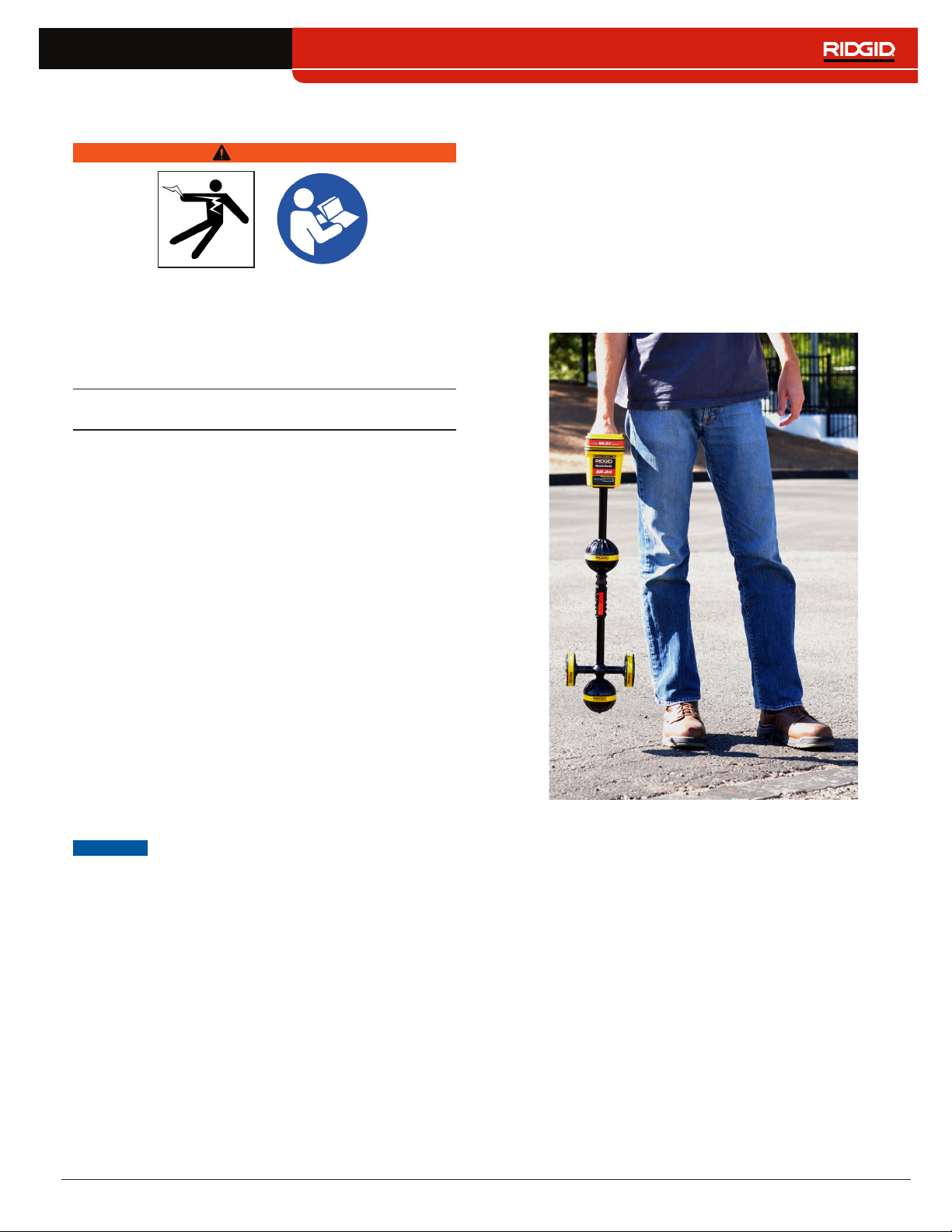
The RIDGID SeekTech SR‑24 receiver gives utility locat‑
ing professionals the information they need to confident‑
ly determine the position of underground utilities�
The SR‑24’s Omnidirectional antenna system measures
electromagnetic signals and calculates the signal’s ori‑
entation strength, depth, and degree of distortion or in‑
terference� The display and the multidimensional audio
cues give you a locating experience that is immediately
intuitive�
For an added degree of confidence, the SR‑24 continu‑
ously monitors the electromagnetic field for interference
from conflicting signals that could distort its shape� When
the SR‑24 detects distortion, the SR‑24 emits audio
cues and displays on‑screen guidance so that appropri‑
ate action can be taken to avoid mismarking the utility’s
position�
Built on the trusted and time tested SR‑20 platform, the
SR‑24 has integrated GPS and Bluetooth
®
technology,
giving a real‑time stream of data to Bluetooth enabled
devices, including smart phones, tablets, and high preci‑
sion GPS instruments�

8 – English
SeekTech SR-24 and SR-20 Specifications
Dimensions
Length 285mm [11�2in]
Width 109mm [4�3in]
Height 790mm [31�1in]
Weight without batteries 1�5kg [3�3lb]
Power
Power rating
6 V, 375 mA (SR‑20)
6 V, 450 mA (SR‑24)
Battery type
Four size C,
1�5V alkaline
(ANSI/NEDA 14A,
IEC LR14), or
1�2V NiMH or Ni‑
Cad rechargeable
batteries
Power consumption
2�25 W (SR‑20)
2�7 W (SR‑24)
LCD
Resolution
Monochrome
240 × 160 pixels
Display size
45mm × 65mm
[1�8 in × 2�6 in]
Contrast ratio 700:1
Brightness
500 Cd/m2
Environmental
Operating temperature
‑20°C to 50°C
[‑4°F to 122°F]
Storage temperature
‑20°C to 60°C
[‑4°F to 140°F]
Relative humidity 5% to 95%
USB
Cable Mini‑B, 1�8 m [6ft]
Type
2�0
SD Card Micro 16 GB
SeekTech SR-24 Specifications
Bluetooth
Type Class 1
Profile RFCOMM
Transmit power 19�1 dBm
Operating spectrum 2402 – 2480 MHz
Receiver sensitivity ‑92 dBm
Operating range
Up to 1,000m
[3,281ft]
GPS
Processor
48‑channel
SiRFstarIV GSD4e
Accuracy
<2�5m [8�2ft]**
Tracking ‑163 dBm
Autonomous acquisition ‑147 dBm
Operating spectrum 1559 – 1610 MHz
**According to the documentation supplied by the man-
ufacturer of the internal SiRFstarIV GPS module, its
nominal accuracy is “<2.5m (65 percent, 24 hour stat-
ic, -130dBm).”
Standard Equipment
• Operator’s manual
• Instructional DVD
• Four size C alkaline batteries
• Marker chips
• Mini‑B USB cable
English – 9
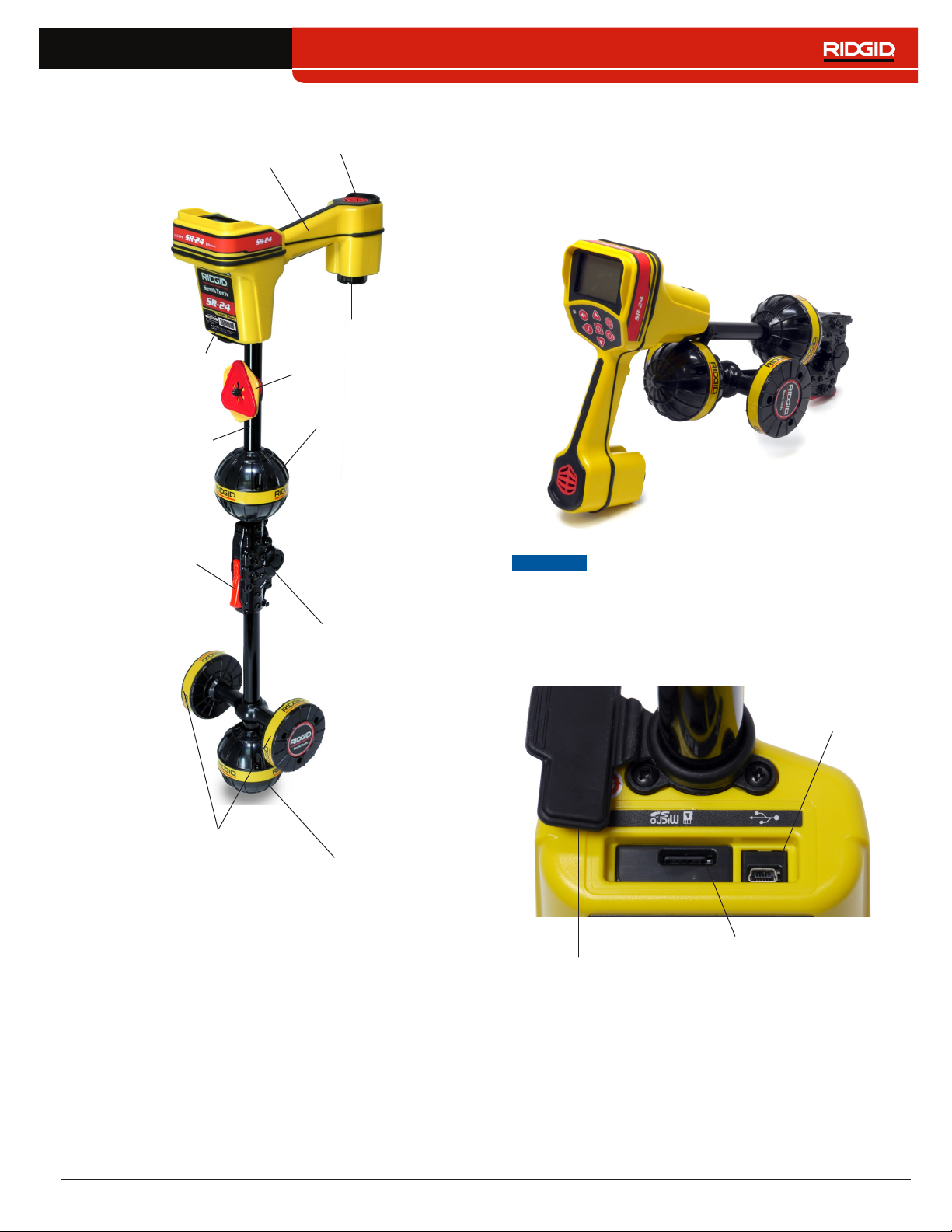
Components
Handle
Speaker
Antenna Mast
Upper Antenna
Folding Joint
Lower Antenna
Gradient Antennas
Release Latch
Battery Compartment
Serial Number Label
Marker Chips
Folding Antenna Mast
Unfold the antenna mast and lock the folding joint into
place� When the job is complete, press the red release
latch to fold the antenna mast� Secure the folding mast
into the clip for storage or transportation�
NOTICE
You must unfold the antenna mast to use
the SR-24. To prevent damage to the
mast, do not snap or whip the SR-24 to
open or close it. Only open and close
the SR-24 manually.
USB Port Cover
USB Port
Micro SD Card Slot
10 – English
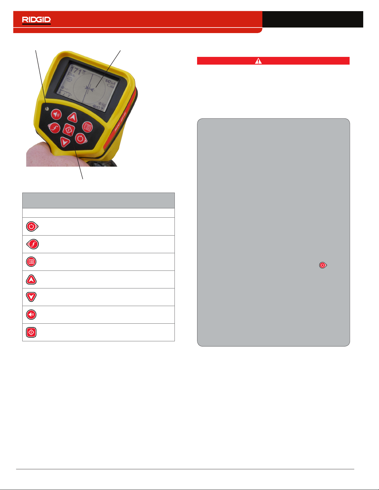
Keypad
Light Sensor LCD Screen
SR-24 Keypad
Key Function
Power Key/Right Arrow Key
Frequency Key/Left Arrow Key
Menu Key
Up Arrow Key
Down Arrow Key
Volume Key
Select Key
Operating Instructions
DANGER
Exposing the utility prior to digging is the only way
to verify its existence, location, and depth. If exca-
vating a utility, periodically recheck the measured
depth and position to avoid damaging the utility and
to identify additional utility signals that may have
been overlooked.
Quick Start
SR-24 is used to refer to both the SR-24 and the
SR-20 throughout this manual. The SR-24 has
integrated GPS and Bluetooth technology. The
SR-20 does not, but is otherwise functionally
identical.
The SR‑24 functions by measuring an electro‑
magnetic signal and estimating the position of its
source� The SR‑24 can locate the signal transmitted
by a RIDGID SeekTech transmitter or Sonde, other
manufacturer’s transmitters, or passive signals from
surrounding metallic conductors�
1� Insert four fully charged, size C, alkaline bat‑
teries into the battery compartment and turn
the knob clockwise to close�
2� Unfold the antenna mast and lock it into place�
3� Power on by pressing the Power Key �
4� Set the receiver and the transmitter to the
same frequency�
5� Begin tracing the line at a logical starting place
such as the transmitter hook up point�
Note: Refer to the Active Line Tracing, Passive Line
Tracing, and Sonde Locating sections that follow
for information on how to locate buried utilities with
the SR-24.
English – 11
Powering the System
Battery operation time varies with battery rating and use�
Four size C, alkaline batteries can power the SR‑24 for
10 to 15 hours�
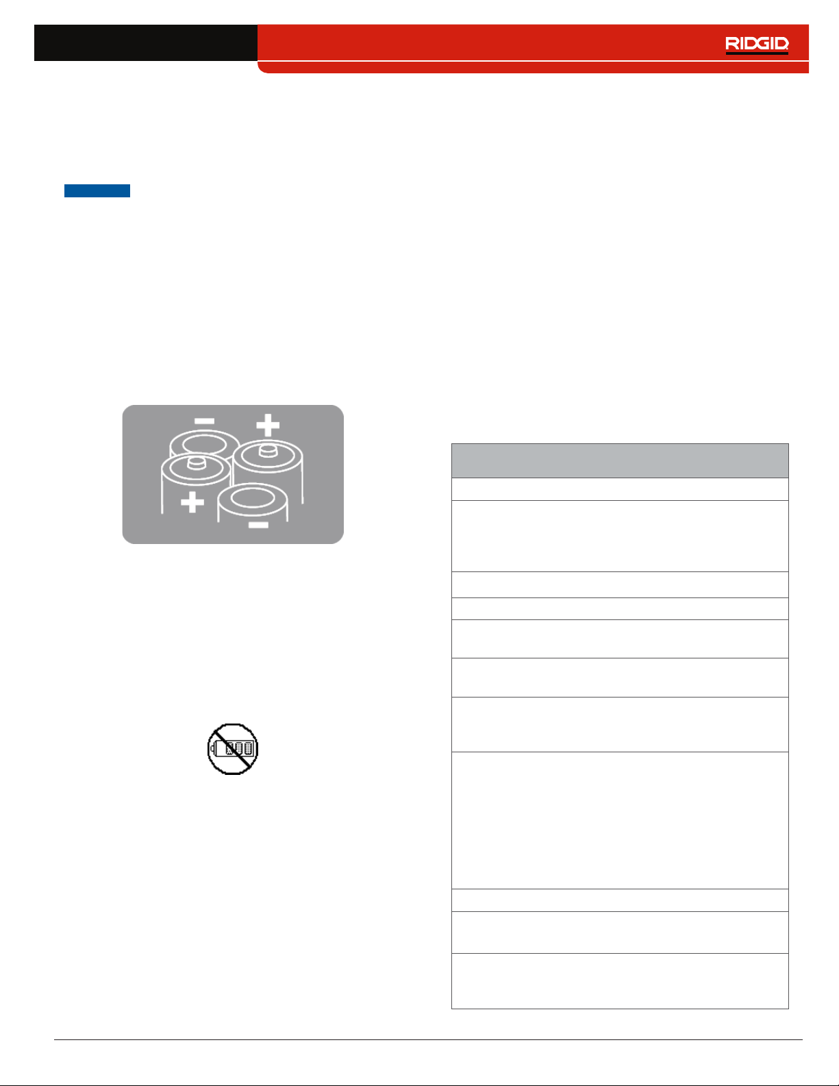
NOTICE
Use batteries that are all the same type.
Mixing alkaline and rechargeable batter-
ies can cause over heating and battery
leakage.
To install or change the batteries, follow these steps:
1� Turn the knob on the battery compartment count‑
er‑clockwise and pull straight out�
2� Insert four size C batteries as shown on the label in‑
side the battery compartment�
Note: Make sure the batteries drop completely into
the compartment.
3� Fit the cover back onto the battery compartment,
press the cover down, and turn the knob clockwise
to close�
Low Battery Warning
When the batteries are low, a low battery warning ap‑
pears on the screen and a tone sounds every 10 minutes
before the SR‑24 powers off� When the low battery warn‑
ing appears, replace the batteries�
Note: If you are using rechargeable batteries, the volt-
age may drop quickly at the end of its charge resulting
in a shortened warning period before power failure.
Receiver Operation Modes
The SR‑24 can operate using two modes: Line Trace
Mode and Sonde Mode�
Line Trace Mode
In Line Trace Mode you can Active Line Trace by inten‑
tionally applying a signal onto the target line through
metal‑to‑metal conduction or non metal‑to‑metal induc‑
tion with a transmitter�
Also in Line Trace Mode, you can Passive Line Trace
by detecting signal energy coupled onto metallic con‑
ductors from nearby energy sources such as power
lines� Passive Line Trace Mode includes Passive Power,
Radio Broadband, and OmniSeek Broadband Modes�
Broadband frequencies target any signal in a range of
frequencies�
Note: Active signals within a broadband range are also
detected.
Line Trace Mode
Active Frequencies
Default
128 Hz
1 kHz
8 kHz
33 kHz
User Programmable 10 Hz – 35 kHz
Passive Frequencies
Default North America
60 Hz
x9
< 4 kHz
Default Europe
50 Hz
x9
< 4 kHz
Default Japan
50 Hz
x9
60 Hz
x9
< 4 kHz
Power Preprogrammed
50 Hz
50
Hz
x5
50 Hz
x9
60 Hz
60 Hz
x5
60 Hz
x9
100 Hz
120 Hz
User Programmable 10 Hz – 35 kHz
Radio Frequency Broadband
4 kHz – 15 kHz
> 15 kHz
OmniSeek Broadband Modes
(All three simultaneously)
< 4 kHz
4 kHz – 15 kHz
> 15 kHz

12 – English
Sonde Mode
Use Sonde Mode to locate a sonde that is inside a pipe,
conduit, or tunnel�
Sonde Mode Frequencies
Default 512 Hz
Preprogrammed
16 Hz
640 Hz
850 Hz
8 kHz
16 kHz
33 kHz
User Programmable 10 Hz – 35 kHz
Note: Sonde Mode and Line Trace Mode can
sometimes use the same frequency. Make sure the
mode icon next to the frequency that you are using is
the mode you intend to be locating with. Depth mea-
surements will be in error if the incorrect mode is used.
User Programmable Custom Frequencies
The SR‑24 comes preprogrammed with a selection of
frequencies that are set by default in Active Line Trace
Mode, Passive Line Trace Mode, and Sonde Mode� You
can also create custom frequencies to use the SR‑24
with transmitters from most manufacturers�
Note: Refer to the Custom Frequencies section for more
information.
Audio
Volume Control
To increase and decrease the volume level of the SR‑24’s
audio cues, first press the Volume Key � You can then
either press the Volume Key to cycle through volume set‑
tings, or press the Volume Key once and use the Up
and Down Arrow Keys to adjust the volume set‑
tings� Press the Select Key to exit the volume settings
screen�
In all modes, if the sound level reaches its maxi‑
mum frequency range (pitch), it rescales to the mid‑
dle of its frequency range� The modulation of fre‑
quency is used to indicate signal strength�
Line Trace Modes
The SR‑24 emits sounds related to the estimated posi‑
tion of the utility� If the utility’s estimated position is on the
left side of the receiver, you will hear a warbling sound�
If the utility’s estimated position is on the right side of
the receiver, you will hear the same warbling sound plus
short clicks�
In Active Line Trace Mode and Passive Line Trace Mode,
the SR‑24 emits a higher pitch as it approaches the tar‑
get� The rising pitch indicates an increasingly strong
Signal Strength�
When local conditions distort the shape of the signal
field, the Tracing Line is fuzzy and the audio contains
static� The degree of fuzziness and the amount of static
in the audio reflect the amount of distortion detected in
the signal field�
Sonde Mode
In Sonde Mode the pitch rises and falls relative to chang‑
es in the Signal Strength� As the SR‑24 moves away from
the sonde, the pitch falls� As the SR‑24 moves closer to
the sonde, the pitch rises�
English – 13
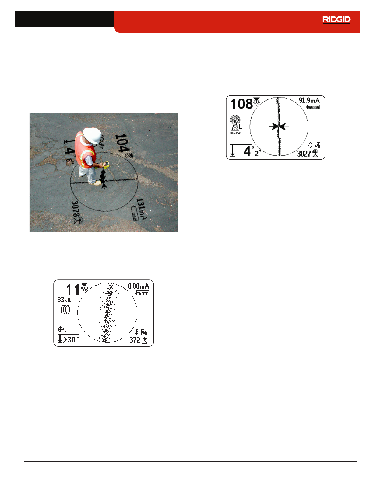
Display Elements
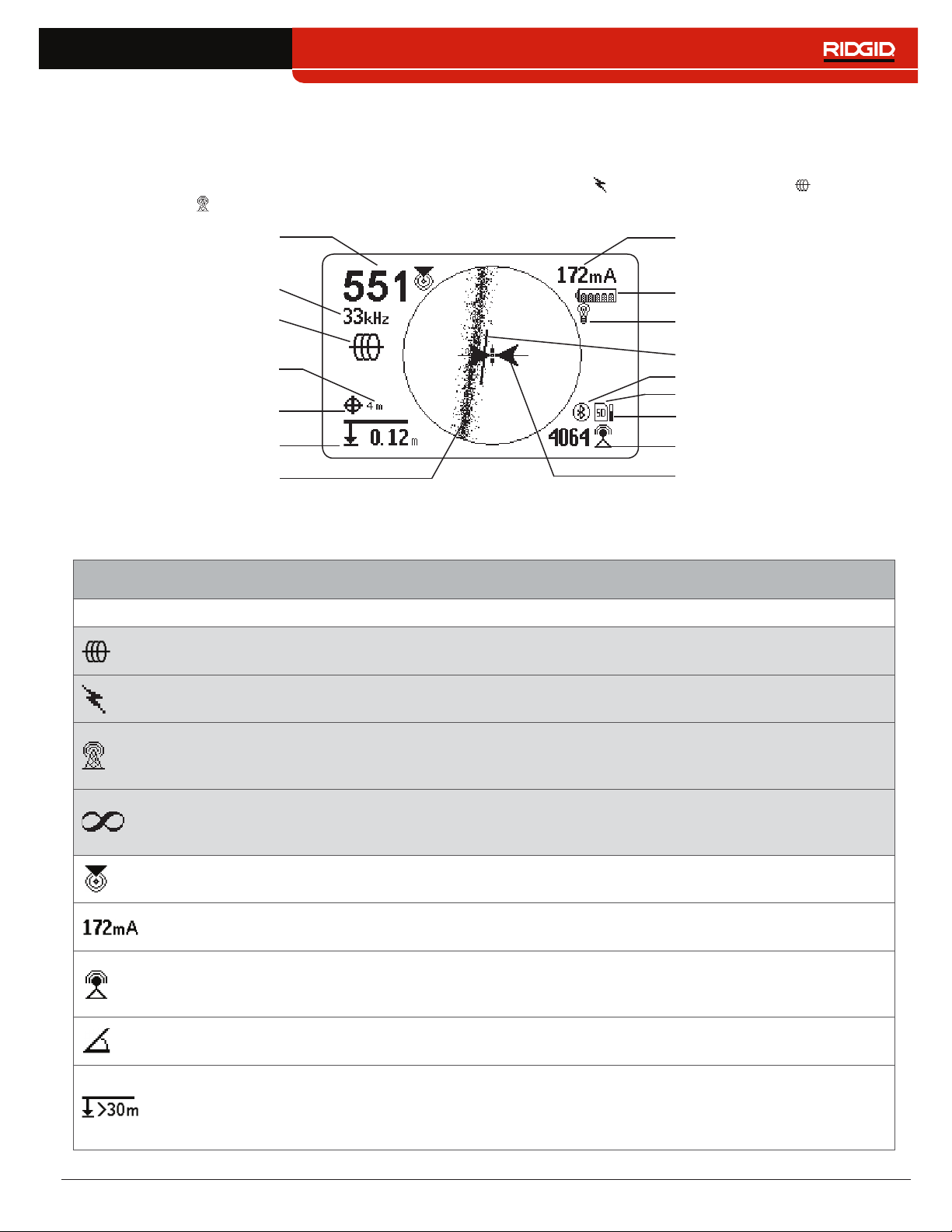
Line Trace Mode Display
The display elements shown below appear in Passive Line Trace Mode , Active Line Trace Mode , and Radio
Broadband Mode �
Proximity Number
Current Measurement (mA)
Battery Status
Receiver Operation Mode
Guidance Line
Guidance Arrows
Measured Depth
Tracing Line
(example shows distortion)
Signal Strength
Bluetooth
SD Card
Currently Set Frequency
GPS
GPS Estimated
Positional Error
Backlight
SD Card Usage Bar Graph
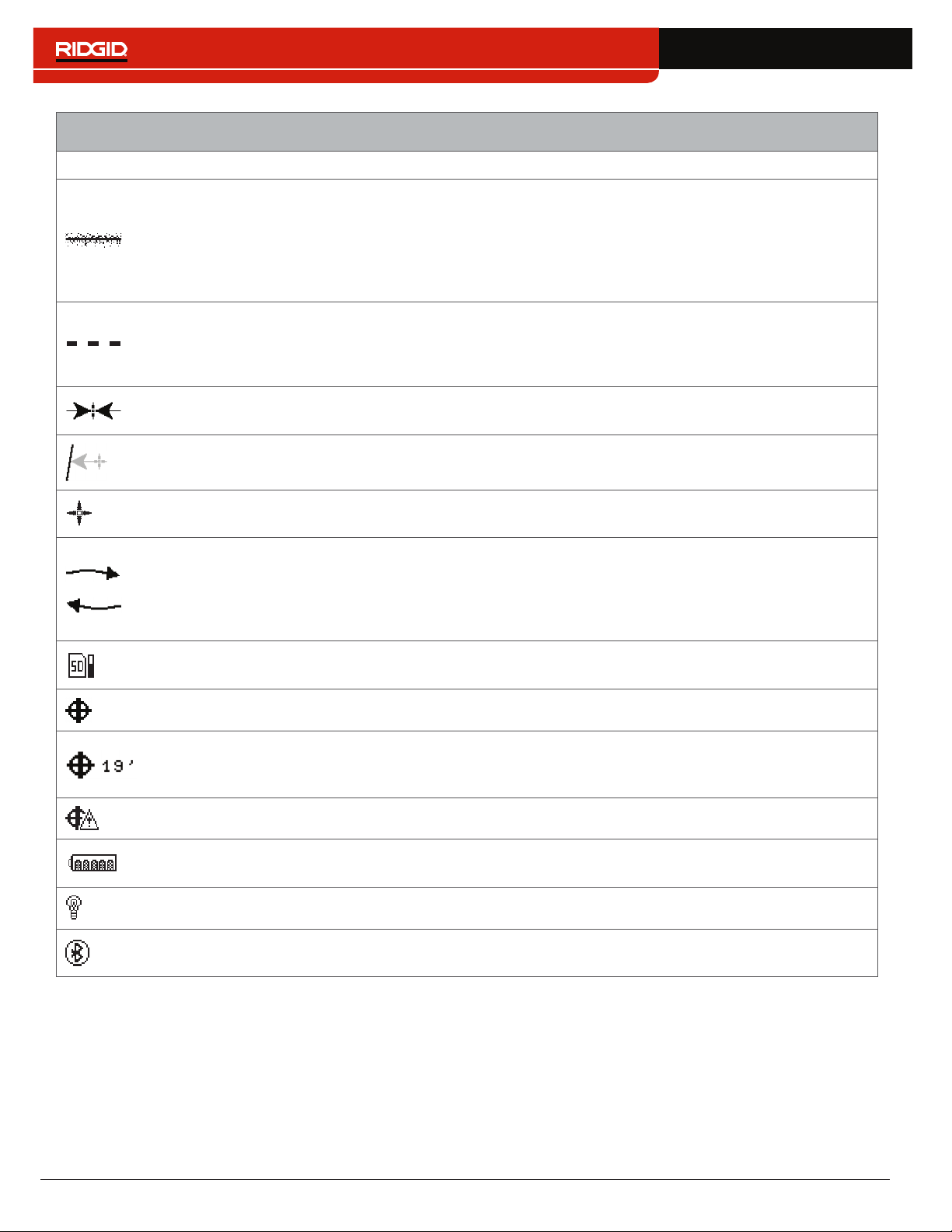
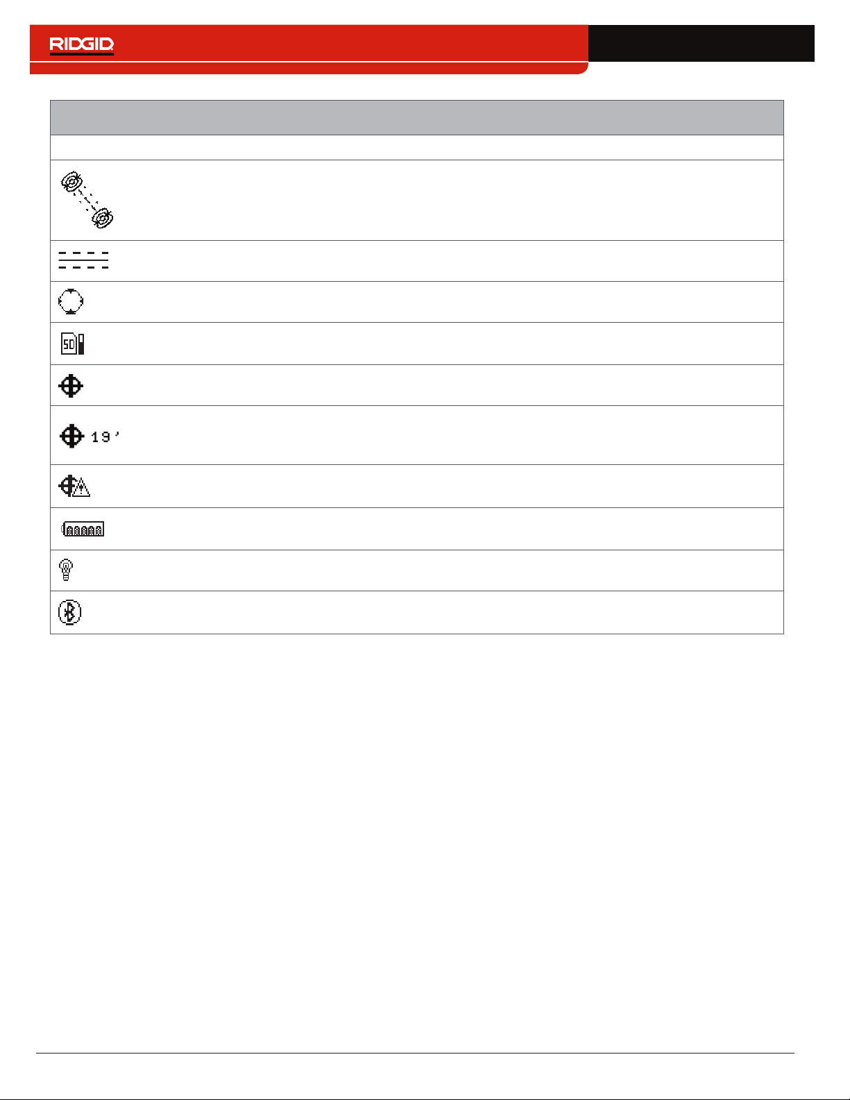
Line Trace Mode Display Elements
Icon Name Description
Active Line Trace
Mode
The Active Line Trace icon indicates the SR‑24 is set to an Active Line Trace
frequency�
Passive Power Line
Trace Mode
The Passive Line Trace icon indicates the SR‑24 is set to a Passive Power
Line Trace frequency�
Passive Radio
Frequency Broadband
Line Trace Mode
The Passive Radio Frequency Broadband Line Trace icon indicates the SR‑24
is set to a Passive Radio Frequency Broadband Line Trace frequency�
Passive OmniSeek
Line Trace Mode
The Passive OmniSeek Line Trace icon indicates the SR‑24 is set to a
Passive OmniSeek Line Trace frequency range� Refer to the OmniSeek
section for more information about OmniSeek Line Tracing.
Proximity Number
The Proximity Number represents the nearness of the target line to the SR‑24�
The larger the number, the closer you are to the target line�
Current Measurement
(mA)
Current Measurement (mA) appears in miliamps when the SR‑24 is directly
over the line�
Signal Strength
Strength of the signal detected by the Omnidirectional antennas� Observe the
Signal Strength to determine the maximum signal strength� At the maximum
signal strength, the receiver is over the target line�
Signal Angle
Signal Angle appears in place of Current Measurement (mA) when the
detected signal is at an angle greater than 35°�
Measured Depth
Measured Depth shows the approximate depth of the target line� The depth
appears in either meters (m) or feet (ft)� In addition to the measured depth
reading, Depth Average displays a Depth Average Report on screen� Refer to
the Depth Average section for more information.
14 – English
Line Trace Mode Display Elements
Icon Name Description
Tracing Line
The orientation and offset of the Tracing Line indicate the direction of the
target line relative to the position of the receiver� The Tracing Line Distortion
Response is enabled by default� When the Tracing Line Distortion Response
is enabled the Tracing Line also represents the amount of distortion detected
by the receiver and the approximate axis of the target line� Increasing levels of
field distortion are represented by increasing degrees of fuzziness�
Distortion Line
The Distortion Line represents the signal from the Upper Antenna node�
Compare the Tracing Line and the Distortion Line to estimate the degree of
distortion on the signal� The Distortion Line is disabled by default and only
appears if the Tracing Line Distortion response is disabled�
Guidance Arrows
When the Guidance Arrows are touching, they indicate the point where the
strength of the field is equal on both sides of the receiver�
Guidance Line
The Guidance Line shows the alignment of the Tracing Line and when the
orientation of the SR‑24 is close to the orientation of the utility�
Cross Hairs
The Cross Hairs are placed at the center of the Active View Area to represent
the receiver’s location�
Rotation Arrows
When the receiver is out of alignment with the target line, two rotation arrows
appear to indicate the direction you should turn the receiver to realign with
the target line� Correct orientation of the receiver is required for the Guidance
Arrows and Guidance Line to function properly� The Rotation Arrows only
appear when the receiver is not in line with the target line�
SD Card and Usage
Bar Graph
The SD Card and Usage Bar Graph icon indicates the SR‑24 is logging to the
installed SD Card� The Usage Bar Graph shows disk space usage�
GPS The GPS icon indicates the internal GPS feature is enabled�
GPS Estimated
Positional Error
GPS Estimated Positional Error is the number next to the GPS icon� It
indicates the Estimated Positional Error of the internal GPS� Refer to the
SR‑24 GPS section for more information�
No GPS Signal Lock Internal GPS signal is not locked and is searching for satellites�
Battery Status
The Battery Status icon indicates the amount of charge remaining in the
batteries�
Backlight The Backlight icon indicates the Backlight is on�
Bluetooth
The Bluetooth icon indicates the Bluetooth feature is enabled and the SR‑24
is connected to and paired with a Bluetooth enabled device�
English – 15
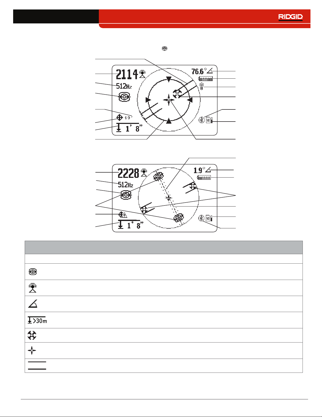
Sonde Mode Display
The display elements shown below appear in Sonde Mode �
Bluetooth
SD Card and Usage
Bar Graph
Signal Strength
Receiver Operation Mode
Pipe Direction
Pole
Zoom Ring
Cross Hairs
Signal Angle
Currently Set Frequency
Battery Status
Backlight
Measured Depth
GPS
GPS Estimated
Positional Error
Equator Line
SD Card and Usage
Bar Graph
Equator Line
Poles
Sonde Equator
No GPS Signal Lock
Bluetooth
Signal Strength
Currently Set Frequency
Receiver Operation Mode
Measured Depth
Battery Status
Signal Angle
Sonde Mode Display Elements
Icon Name Description
Sonde Mode
The sonde icon underneath the currently set frequency, indicates the SR‑24 is
set to a sonde frequency�
Signal Strength
Strength of the signal detected by the omnidirectional antennas� Observe the
signal strength to determine the maximum signal strength�
Signal Angle
The signal angle displays the measured polar angle of the SR‑24 to the sonde
dipole field�
Measured Depth
Measured depth shows the approximate depth of the target line� The depth
appears in either meters (m) or feet (ft)�
Pole The pole icon represents the location of a pole of the sonde’s dipole field�
Cross Hairs
The cross hairs are placed at the center of the active view area to represent the
receivers location�
Pipe Direction The pipe direction represents the approximate orientation of the sonde’s axis�
16 – English
Sonde Mode Display Elements
Icon Name Description
Sonde Equator
Two sonde equator icons appear along the equator line once the first pole has
been located�
Equator Line The equator line represents the equator of the sonde’s field�
Zoom Ring The Zoom Ring appears when the receiver moves close to one of the Poles�
SD Card and Usage
Bar Graph
The SD Card and Usage Bar Graph icon indicates the SR‑24 is logging to the
installed SD Card� The Usage Bar Graph shows disk space usage�
GPS The GPS icon indicates the internal GPS feature is enabled�
GPS Estimated
Positional Error
GPS Estimated Positional Error is the number next to the GPS icon� It indicates
the Estimated Positional Error of the internal GPS� Refer to the SR-24 GPS
section for more information.
No GPS Signal
Lock
Internal GPS signal is not locked and is searching for satellites�
Battery Status
The Battery Status icon indicates the amount of charge remaining in the
batteries�
Backlight The Backlight icon indicates the Backlight is on�
Bluetooth
The Bluetooth icon indicates the Bluetooth feature is enabled and the SR‑24 is
connected to and paired with a Bluetooth enabled device�
Note: Refer to the Customizing Display Elements section for instructions on how to customize display elements and for
information about additional display options.
English – 17
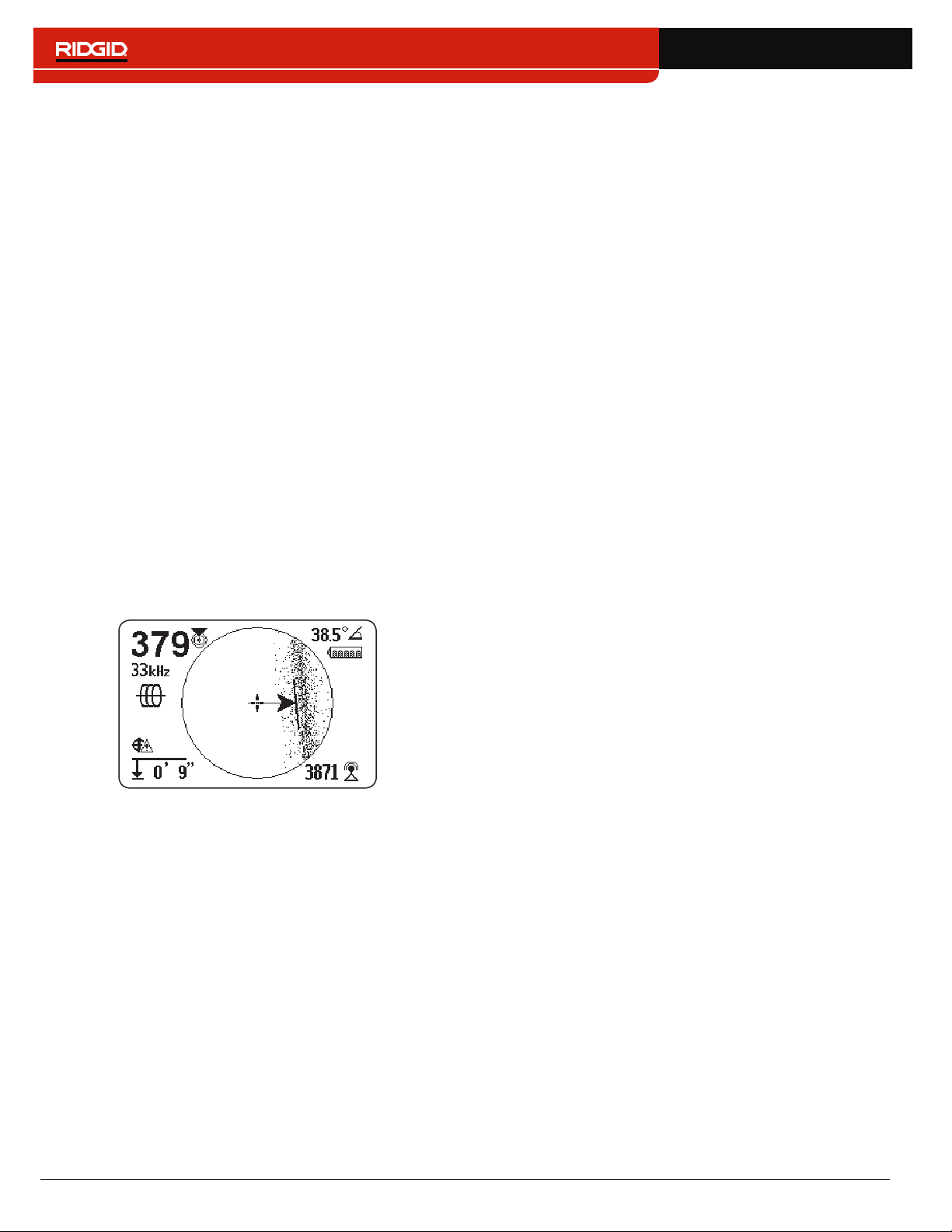
Understanding the Display
Refer to the SR‑20 Instructional Video for a demonstra‑
tion of how the display elements work during a locate
and to see how they work together to make your locates
accurate and efficient� The video is on a DVD included
with the SR‑24 manual pack or can be viewed online:
www�RIDGID�com/us/en/instructional‑videos
Tracing Line
The Tracing Line shows the location and direction of the
target line’s signal, change in direction of the target line,
and the amount of distortion on the target line�
If the signal is clear and the detected field is undistorted,
the following occurs:
• The Tracing Line appears as a clear, single line�
• The Guidance Arrows point to the center of the
screen�
• The Guidance Line aligns with the Tracing Line�
If the Tracing Line appears fuzzy, the field may be distort‑
ed by interfering electromagnetic fields� As the distortion
increases, the Tracing Line appears increasingly fuzzy
and the audio cue increases static noise�
Guidance Arrows and the Guidance Line
The Guidance Arrows reflect the difference in the Signal
Strength measurement made on either side of the
SR‑24� They point in the direction of the strongest signal�
The Guidance Line appears between the arrows when
the receiver is aligned with the target line�
The Guidance Line gets longer as the receiver aligns
with the direction of the target line� For best guidance
accuracy, align the Tracing Line and Guidance Line be‑
tween the Guidance Arrows� As a general rule, if there
is a moderate mismatch between the Tracing Line and
Guidance Line, the Guidance Line will be closer to the
actual utility position� Any mismatch is an indication of
distortion�
18 – English
Distortion
Electromagnetic receivers like the SR‑24 require a sig‑
nal directly from the target utility without modification
by environmental factors to obtain optimal accuracy�
Environmental factors can include the presence of near‑
by metallic conductors or the addition of electromagnetic
fields from other sources like fields radiating from adja‑
cent utilities� These factors may distort the shape of the
field received by the SR‑24 and are experienced by the
SR‑24 as distortion� The SR‑24 uses its Omnidirectional
antennas and gradient antennas to measure distortion
and provide audio and on‑screen indicators�
Nearby metallic conductors can distort the shape of the
target line’s electromagnetic field� The SR‑24 gives three
different indicators to alert you that distortion is present�
Take extra precautions when distortion is present to
confirm the accuracy of the locate.
Note: Refer to the Improving and Confirming Accuracy
section for information on improving the locate.
The Tracing Line Distortion Response activates when dis‑
tortion is detected� The Tracing Line Distortion Response
makes the Tracing Line appear fuzzy when distortion is
present� The fuzzier and more spread out the Tracing
Line is, the greater the distortion�
You can set the Tracing Line Distortion Response to
high “H,” medium “M,” low “L” (default), or “OFF�” Set the
Tracing Line Distortion Response to high to increase its
sensitivity to distortion�
Note: To change the Tracing Line Distortion Response
sensitivity settings, refer to the Customizing Display
Elements section.
When the Distortion Line is enabled, the tracing line fuzz‑
iness is turned off� The Tracing Line becomes a solid line
and the Distortion Line (dashed line) appears when dis‑
tortion is present� The dashed Distortion Line represents
the signal detected by the Upper Antenna and the solid
Tracing Line represents the signal detected by the Lower
Antenna�
Distortion is likely if the Distortion Line does not align
with the Tracing Line� The Distortion Line and the Tracing
Line may move randomly if the SR‑24 receives a weak
signal�
English – 19
Active Line Tracing
In Active Line Tracing Mode, the SR‑24 detects signals
generated by a line transmitter, such as the RIDGID
SeekTech ST‑33Q+� Transmitters can energize a target
line with a tracing signal in three ways: Direct Connect
(metal‑to‑metal contact), with an Inductive Clamp, or
using the transmitter’s internal transmitting antenna
through Induction�
Note: For complete instructions on generating a locating
signal with a transmitter, refer to the operator’s manual
that came with the line transmitter you are using.
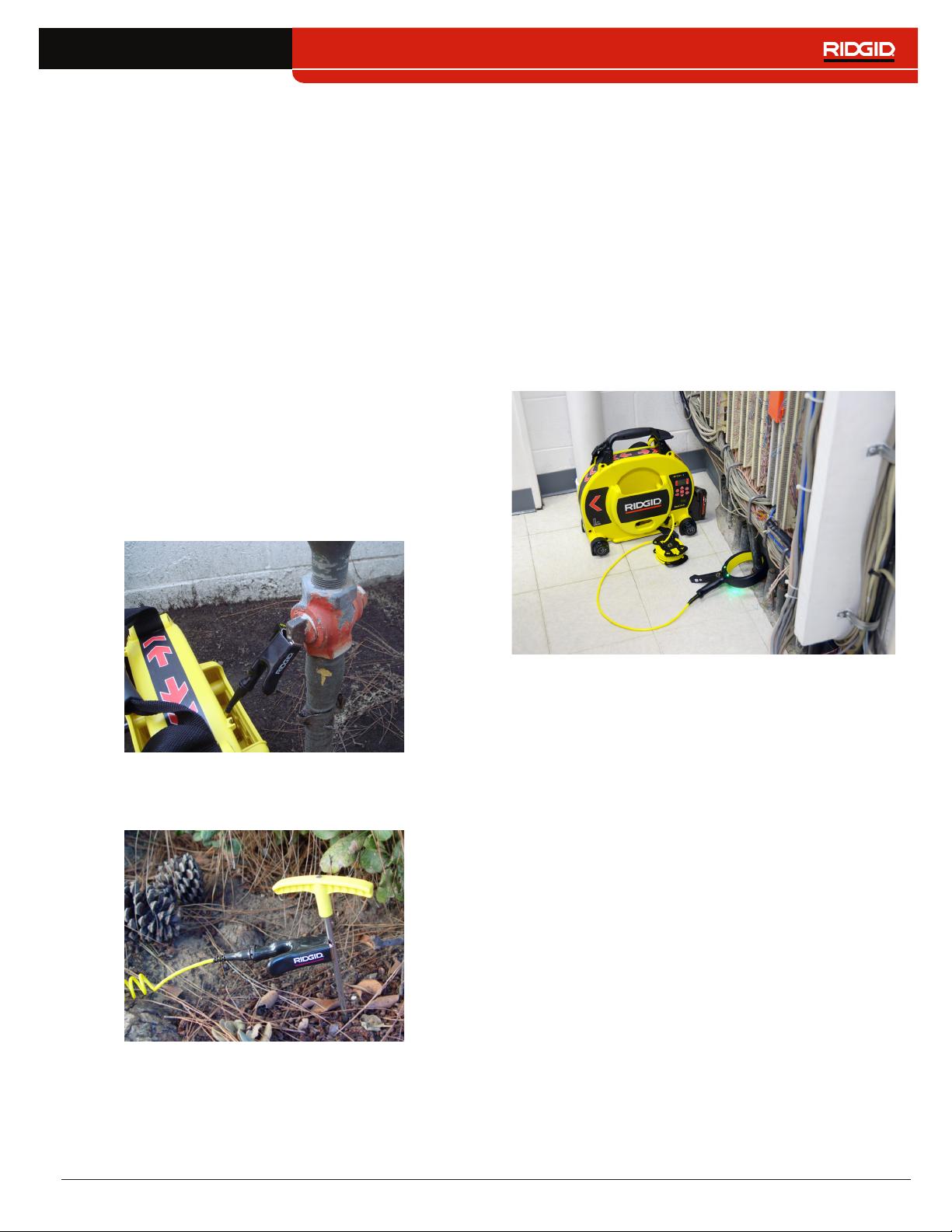
Direct Connect
Energizing a target line by direct connection requires
metal‑to‑metal contact�
1� Use the clip’s built‑in scraper to remove paint, dirt,
or debris from the connection point to ensure good
metal‑to‑metal contact�
2� Attach one of the transmitter’s lead clips to the tar‑
get line�
3� Push the grounding stake into the ground as far as
possible and attach the transmitter’s other lead clip
to it�
With the transmitter’s lead clips attached to the tar‑
get line and the grounding stake, a circuit is created
for the signal to travel� The circuit allows current to
flow, energizing the target line�
Note: A weak ground connection can cause a poor
tracing circuit. Refer to the Improving the Tracing
Circuit section for more information on grounding.
4� Begin tracing the line�
Note: Refer to Tracing the Target Line section for in-
structions on how to trace the target line.
Inductive Clamp
To use the Inductive Clamp, connect it to the transmit‑
ter and close the clamp around the exposed pipe� The
transmitter energizes the clamp and induces a current
onto the target line� The clamp must be fully closed for it
to operate properly�
20 – English
Induction
To induce a signal onto the target line, place the trans‑
mitter over and in line with the target line� The transmit‑
ter must be oriented with respect to the line, as shown
below, to operate properly (orientation is specific to the
transmitter model)�
The transmitter’s internal transmitting antenna generates
a signal that energizes correctly oriented, nearby metal‑
lic objects�
To improve the circuit, ensure that both ends of the target
line are grounded and place the transmitter away from
other metallic conductors that may be nearby�
Note: For complete instructions on generating a locating
signal with a transmitter, please consult the operator’s
manual for your line transmitter.
Induction and Air-Coupling
WARNING
Air-coupling can lead to false locates.
With Induction, the transmitter broadcasts a signal in all
directions� If the receiver is too near to the transmitter,
the signal broadcast through the air will be stronger than
the signal from the target line underground� This is called
air‑coupling and it can prevent you from getting an accu‑
rate locate�
The impact of air‑coupling varies with each locate and
can occur at ranges greater than 20m [70ft] if the utili‑
ty is deep or poorly grounded� Very weak inductive cou‑
pling and deep utilities result in greater air‑coupling rang‑
es� Always confirm the detection of utilities and the depth
measurement readings by testing for air‑coupling� Read
the following sections for instructions on how to test for
air‑coupling�
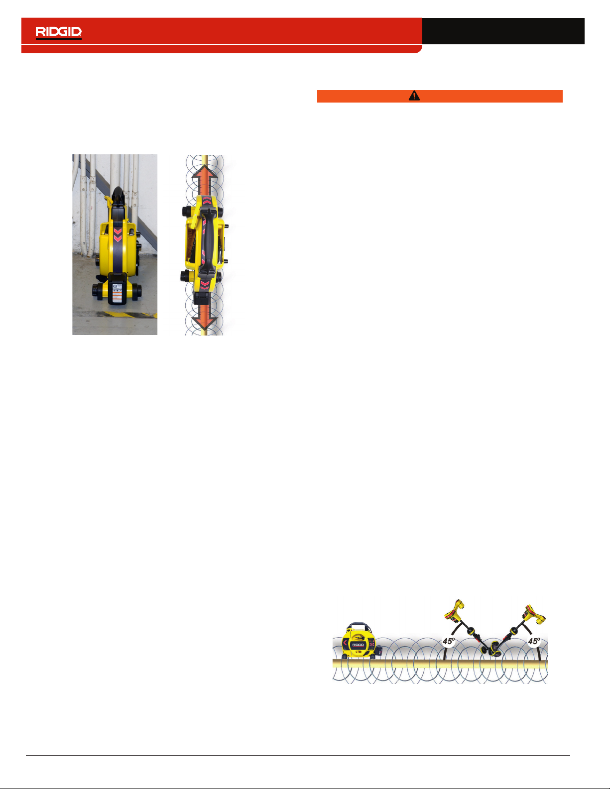
Testing for Air-Coupling
When the receiver is severely air coupled it will warn you
by hiding the Tracing Line and Guidance Arrows� Even
if you see these displayed, the receiver may still be dis‑
playing results corrupted by air‑coupling� There are two
ways you can test for air‑coupling: the 45° tilt test and the
depth verification test�
To perform the 45° tilt test, follow these steps:
1� With the SR‑24 aligned with the target line, touch
the Lower Antenna to the ground and tilt the SR‑24
at a 45° angle toward the transmitter�
2� Note the depth�
3� With the Lower Antenna still touching the ground, tilt
the SR‑24 away from the transmitter at a 45° angle�
4� Note the depth�
If the tilted depth reading changes significantly compar‑
ing the two cases, air‑coupling is occurring�
Note: The depth reading will not be an accurate reading
of the target line’s depth.
 Loading...