


micro CD-100 Operator’s Manual
micro CD-100 Combustible Gas Detector
 WARNING!
Read this Operator’s Manual carefully before using this tool. Failure to understand and follow the contents of this manual may result in electrical shock, fire and/or serious personal injury.
•Français – 11
•Castellano – pág. 23
• Türkçe – 35
Русский• язык – 47

micro CD-100 Combustible Gas Detector
Table of Contents |
|
Recording Form for Machine Serial Number ......................... |
1 |
Safety Symbols......................................................................... |
2 |
General Safety Rules |
|
Work Area Safety ................................................................... |
2 |
Electrical Safety...................................................................... |
2 |
Personal Safety ...................................................................... |
2 |
Equipment Use and Care ....................................................... |
3 |
Service.................................................................................... |
3 |
Specific Safety Information |
|
Combustible Gas Detector Safety .......................................... |
3 |
Description, Specifications And Standard Equipment |
|
Description.............................................................................. |
4 |
Specifications ......................................................................... |
4 |
Controls .................................................................................. |
6 |
LED Display ........................................................................... |
6 |
Standard Equipment............................................................... |
6 |
Changing/Installing Batteries.................................................. |
7 |
Pre-Operation Inspection ........................................................ |
7 |
Set-Up and Operation .............................................................. |
8 |
Maintenance |
|
Cleaning ................................................................................. |
9 |
Sensor Calibration/Replacement............................................ |
9 |
Storage...................................................................................... |
9 |
Service and Repair................................................................. |
10 |
Disposal .................................................................................. |
10 |
Battery Disposal..................................................................... |
10 |
Troubleshooting ..................................................................... |
10 |
Lifetime Warranty ..................................................... |
Back Cover |
|
*Original Instructions - English |
II
 micro CD-100
micro CD-100
Combustible Gas Detector
micro CD-100 Combustible Gas Detector
Record Serial Number below and retain product serial number which is located on nameplate.
Serial
No.
micro CD-100 Combustible Gas Detector
Safety Symbols
In this operator’s manual and on the product, safety symbols and signal words are used to communicate important safety information.This section is provided to improve understanding of these signal words and symbols.
This is the safety alert symbol. It is used to alert you to potential personal injury hazards. Obey all safety messages that follow this symbol to avoid possible injury or death.

 DANGER DANGER indicates a hazardous situation which, if not avoided, will result in death or serious injury.

 WARNING WARNING indicates a hazardous situation which, if not avoided, could result in death or serious injury.

 CAUTION CAUTION indicates a hazardous situation which, if not avoided, could result in minor or moderate injury.
NOTICE NOTICE indicates information that relates to the protection of property.
This symbol means read the operator’s manual carefully before using the equipment.The operator’s manual contains important information on the safe and proper operation of the equipment.
General Safety Rules
 WARNING
Read all safety warnings and instructions. Failure to follow the warnings and instructions may result in electric shock, fire and/or serious injury.
SAVE THESE INSTRUCTIONS!
The EC Declaration of Conformity (890-011-320.10) will accompany this manual as a separate booklet when required.
Work Area Safety
•Keep your work area clean and well lit. Cluttered or dark areas invite accidents.
•Do not operate equipment in explosive atmospheres, such
as in the presence of flammable liquids, gases or dust.
Equipment can create sparks which may ignite the dust or fumes
•Keep children and by-standers away while operating equipment. Distractions can cause you to lose control.
Electrical Safety
•Avoid body contact with earthed or grounded surfaces such as pipes, radiators, ranges and refrigerators. There is an increased risk of electrical shock if your body is earthed or grounded.
•Do not expose equipment to rain or wet conditions. Water entering equipment will increase the risk of electrical shock.
Personal Safety
•Stay alert, watch what you are doing and use common sense when operating equipment. Do not use equipment while you
2

 micro CD-100 Combustible Gas Detector
are tired or under the influence of drugs, alcohol or medication. A moment of inattention while operating equipment may result in serious personal injury.
•Use personal protective equipment. Always wear eye protection. Protective equipment such as dust mask, non-skid safety shoes, hard hat or hearing protection used for appropriate conditions will reduce personal injuries.
•Do not overreach. Keep proper footing and balance at all times. This enables better control of the power tool in unexpected situations.
Equipment Use and Care
•Do not force equipment. Use the correct equipment for your application. The correct equipment will do the job better and safer at the rate for which it is designed.
•Do not use equipment if the switch does not turn it ON and OFF. Any tool that cannot be controlled with the switch is dangerous and must be repaired.
•Disconnect the batteries from the equipment before making any adjustments, changing accessories or storing. Such preventive safety measures reduce the risk of injury.
•Store idle equipment out of the reach of children and do not allow persons unfamiliar with the equipment or these instructions to operate the equipment. Equipment can be dangerous in the hands of untrained users.
•Maintain equipment. Check for misalignment or binding of moving parts, missing parts, breakage of parts and any other condition that may affect the equipment’s operation. If damaged, have the equipment repaired before use. Many accidents are caused by poorly maintained equipment
•Use the equipment and accessories in accordance with these instructions, taking into account the working conditions and the work to be performed. Use of the equipment for
operations different from those intended could result in a hazardous situation.
•Use only accessories that are recommended by the manufacturer for your equipment. Accessories that may be suitable for one piece of equipment may become hazardous when used with other equipment.
•Keep handles dry and clean; free from oil and grease. Allows for better control of the equipment.
Service
•Have your equipment serviced by a qualified repair person using only identical replacement parts. This will ensure that the safety of the tool is maintained.
Specific Safety Information
 WARNING
This section contains important safety information that is specific to this tool.
Read these precautions carefully before using the micro CD100 Combustible Gas Detector to reduce the risk of fire, explosion or other serious personal injury.
SAVE THESE INSTRUCTIONS!
Keep this manual with the tool for use by the operator.
Combustible Gas Detector Safety
•High concentrations of combustible gases can cause explosions, fires, asphyxia and other hazards that could cause serious personal injury or death. Know the characteristics of the gas you are working with and use proper precautions to avoid hazardous conditions.
•Do not use the micro CD-100 Combustible Gas Detector as a confined space or personal safety device.This could cause
3

micro CD-100 Combustible Gas Detector
serious personal injury. The micro CD-100 does not specifically identify the combustible gas type or exact concentration.
•Always turn on and calibrate the gas detector in an area known to be free of combustible gases. Calibration in an area containing combustible gas will result in incorrect calibration and lower than actual readings. This could result in combustible gases not being detected.
If you have any question concerning this RIDGID® product:
• Contact your local RIDGID distributor.
• Visit www.RIDGID.com or www.RIDGID.eu to find your local RIDGID contact point.
• Contact Ridge Tool Technical Service Department at rtctechserandard
vices@emerson.com, or in the U.S. and Canada call (800) 5193456.
Description, Specifications
And Standard Equipment
Description
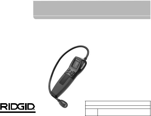
The RIDGID® micro CD-100 Combustible Gas Detector is a gas leak locating tool that is used to identify the presence of and isolate the source location of combustible gases such as methane, propane, butane, ammonia and others (see page 5 for a more complete list) by indicating relative gas concentrations. Even low levels of combustible gas can be detected in seconds.
The micro CD-100 detects gas concentrations through the use of an internal sensor. This sensor is heated during operation. As the heated sensor interacts with gases, the unit immediately indicates to the user that combustible gases are present. The micro CD-100 indicates the presence of combustible gases with visual, audio and vibration feedback mechanisms. There are five (5) threshold levels of measurement within two (Low and High) settings of sensitivity.
When the tool senses the presence of a combustible gas, it will tell the operator by blinking the appropriate light(s), triggering the appropriate audible alert or providing the appropriate vibration alert.
The micro CD-100 comes equipped with an attached flexible 16" probe hose.
Specifications
Visual Alert ................................... |
5 Red LEDs: Gas Measuring |
|
Levels; Sensitivity Visual Alert |
Audible Alert(85 db) ...................... |
Loud Audible Ticking Rate |
|
(w/Continuous Modulation |
|
Proportional to Gas Level) |
Vibration Alert ............................... |
St |
Sensitivity*...................................... |
40 ppm (methane) |
Response Time .............................. |
< 2 Seconds |
Range............................................. |
0 – 6400 ppm (methane) |
Sensitivity* Level |
|
(methane) (HIGH)......................... |
5 Levels: |
|
40/80/160/320/640 ppm |
Sensitivity* Level |
|
(methane) (LOW).......................... |
5 Levels: |
|
400/800/1600/3200/6400 ppm |
Warm Up Calibration .................... |
Automatic |
Warm Up Time.............................. |
50 Seconds Max |
Operating Buttons......................... |
Five: Power ON/OFF, High |
|
Sensitivity, Low Sensitivity, |
|
Audio Alerts, Vibration Alerts |
Batteries ....................................... |
4 x “AA” |
Low Battery Status ....................... |
Low and High Sensitivity LED |
|
Solid |
Sensor Connection ....................... |
Plug-In |
*Sensitivity level may vary for other gases.
4
|
|
|
|
|
|
micro CD-100 Combustible Gas Detector |
|
|
|
|
|
|
|
|
|
|
|
||
|
|
|
|
|
|
|
|
||
|
|
|
|
|
|
|
|
|
|
|
Expected Sensor Life |
.....................5 Years |
Features |
|
|
||||
|
Probe ............................................ |
Flexible 16"/400mm |
• 16" Adjustable Probe |
|
|
||||
|
Weight........................................... |
16 oz/450 grams |
• Replaceable Sensor |
|
|
||||
|
Detected Gases |
|
• TRI Mode Detection |
|
|
||||
|
|
|
|
|
|
|
|
|
|
|
Gases Detected |
|
Common Mixtures That Would Include |
|
|
|
|
|
|
|
|
|
|
or Emit More Than One Of These Gases |
|
|
|
|
|
|
Methane |
|
|
|
|
|
|
|
|
|
Hydrogen |
|
Natural Gas* |
|
|
|
|
|
|
|
Propane |
|
|
|
|
|
|
|
|
|
Ethylene |
|
Paint Thinners |
|
|
|
|
|
|
|
Ethane |
|
|
|
|
|
|
|
|
|
Hexane |
|
|
|
|
|
|
|
|
|
Benzene |
|
Industrial Solvents |
|
|
|
|
|
|
|
Iso-Butane |
|
|
|
|
|
|
|
|
|
Ethanol |
|
|
|
|
|
|
|
|
|
Acetaldehyde |
|
Dry Cleaning Fluids |
|
|
|
|
|
|
|
Formaldehyde |
|
|
|
|
|
|
|
|
|
Toluene |
|
|
|
|
|
|
|
|
|
P-Xylene |
|
Gasoline |
|
|
|
|
|
|
|
Ammonia |
|
|
|
|
|
|
|
|
|
Hydrogen Sulfide |
|
|
|
|
|
|
|
|
*Natural Gas typically consists of a high percentage of methane and smaller percentages of propane and other gases.
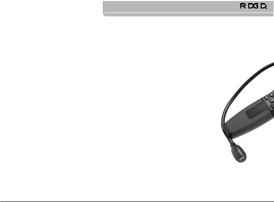
Figure 1 – RIDGID micro CD-100 Combustible Gas Detector
5

|
|
|
|
micro CD-100 Combustible Gas Detector |
|
|
|
|
|
|
|
|
|
|
|
||
|
|
|
|
|
|
|
||
Controls |
|
|
Display |
|
||||
|
|
|
|
|
|
|
|
LED Display |
|
|
|
|
|
Display |
|
|
|
|
|
|
|
Audible |
|
|
Low Sensitivity |
|
|
|
|
|
Alert |
|
|
|
|
|
|
|
Enable/Disable |
High Sensitivity |
Indicator |
High |
||
|
|
|
|
|||||
|
|
|
|
|
Selector |
|
Sensitivity |
|
|
|
|
|
|
|
|
|
Indicator |
Vibration Alert |
Low Sensitivity |
|
|
|||||
Enable/Disable |
|
Warm Up |
||||||
Selector |
|
|||||||
|
|
|
|
|
|
Indicator |
||
|
|
|
|
|
|
|
|
|
|
|
|
|
Power |
|
|
|
|
|
|
|
|
ON/OFF |
|
|
|
|
Battery
Cover
Figure 3 – micro CD-100 Display
Figure 2 – micro CD-100 Parts
Standard Equipment
• micro CD-100 |
• Replaceable Gas Sensor |
• Batteries 4 x AA |
• Operator's Manual |
6
 micro CD-100 Combustible Gas Detector
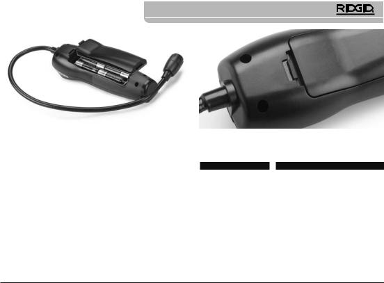
Figure 4 – Removing Battery Compartment Cover
Changing/Installing Batteries
The micro CD-100 comes without the batteries installed. If the high sensitivity (yellow) and low sensitivity (white) lights are ON at the same time, this indicates that the batteries need to be replaced.
Remove the batteries prior to long term storage or shipment to prevent battery leakage. Never change batteries in the presence of combustible gases to reduce the risk of explosions, fires and other serious injury.
1.Depress the battery compartment cover catch (See Figure 4) and remove the cover. If needed, remove batteries.
2.Install four AA alkaline batteries (LR6), observing correct polarity as indicated in the battery compartment.
3.Replace the battery compartment cover. Confirm securely attached.
4.Confirm battery cover clasp is locked. (Figure 5)
Figure 5 – Battery Cover Clasp
Pre-Operation Inspection
 WARNING
Before each use, inspect your micro CD-100 and correct any problems to reduce the risk of injury or incorrect measurements.
1.Clean any oil, grease or dirt from equipment. This aids inspection.
2.Inspect the micro CD-100 for any broken, worn, missing, misaligned or binding parts, or any other condition which may prevent safe and normal operation.
3.Check that the warning labels are present, firmly attached and readable. (See Figure 6.)
4.If any issues are found during the inspection, do not use the micro CD-100 until it has been properly serviced.
5.Following the Set-Up and Operation instructions, turn ON and
7
micro CD-100 Combustible Gas Detector
calibrate the gas detector. Once calibration is complete use a combustible gas source (such as an unlit lighter), to confirm that the gas detector senses the gas. If the gas detector does not sense the gas, do not use the unit until it has been properly serviced. Remove the gas source and allow several minutes for the sensor to stabilize prior to use.
Figure 6 – Warning Labels
Set-Up and Operation
 WARNING
High concentrations of combustible gases can cause explosions, fires, asphyxia and other hazards that could cause serious personal injury or death. Know the characteristics of the gas you are working with and use proper precautions to avoid hazardous conditions.
Do not use the micro CD-100 Combustible Gas Detector as a confined space or personal safety device. This could cause serious personal injury. The micro CD-100 does not specifically identify the combustible gas type or exact concentration.
Always turn on and calibrate the gas detector in an area known to be free of combustible gases. Calibration in an area containing combustible gas will result in incorrect calibration and lower than actual readings. This could result in combustible gases not being detected.
Set up and Operate the gas detector according to these procedures to reduce the risk of fire, explosions and serious injury and incorrect measurements.
1.Check for an appropriate work area as indicated in the General Safety Section.
2.Determine the application and confirm that you have the correct equipment. See the Specifications section for information on sensitivity, gases detected and other information.
3.Make sure that all equipment has been properly inspected.
4.In an area where combustible gases are known to not be present, turn on the gas detector by pressing and releasing the ON/OFF button. For one second the gas detector will vibrate, beep, and the first level red light will come on to indicate that the unit is ON. The gas detector then starts an approximately 50 second sensor heat up and calibration, during which the first level red light is blinking.
Once the calibration is complete, for one second, all level lights will flash, and if the audible and vibration alerts are ON, the unit will beep and vibrate. Then either the high (yellow) or low (white) light will be ON. If the high (yellow) and low (white) sensitivity lights are ON at the same time, this indicates that the batteries need to be replaced. If all display lights are ON, this indicates that the sensor has failed and that the unit needs to be serviced.
If the gas detector is left ON for more than five minutes with no activity, it will automatically shut OFF to conserve the batteries.
5.The Audible Alert and Vibration Alert retain the previous state the detector was last in and can be turned ON or OFF if de-
8
 micro CD-100 Combustible Gas Detector
sired. Press and release the Audible Alert button to turn it ON and OFF. The gas detector will beep once when the Audible Alert is turned ON and OFF. Press and release the Vibration Alert button to turn it ON and OFF.The gas detector will vibrate twice when turning the Vibration Alert ON and vibrate once when turning the Vibration Alert OFF.
6.Enter the area to be monitored. Pay close attention to the gas level indicators (see Table 1). As gas levels increase, more red level lights will come on and the frequency of the Audible Alert beeping and the Vibration Alert vibration will increase. See Table 1 for information on methane concentration levels and gas detector feedback.
Table 1 – Gas Detector Feedback For Methane Concentration
Levels
Low Sensitivity |
High Sensitivity |
|
Level Lights |
|
Audible Alert |
||
White Light ON |
Yellow Light ON |
L1 |
L2 |
L3 |
L4 |
L5 |
Beeping |
< 400 ppm |
< 40 ppm |
OFF |
OFF |
OFF |
OFF |
OFF |
1 cyc/sec |
400…800 ppm |
40…80 ppm |
ON |
OFF |
OFF |
OFF |
OFF |
1.02 cyc/sec |
800…1600 ppm |
80…160 ppm |
ON |
ON |
OFF |
OFF |
OFF |
1.2 cyc/sec |
1600…3200 ppm |
160…320 ppm |
ON |
ON |
ON |
OFF |
OFF |
1.65 cyc/sec |
3200…6400 ppm |
320…640 ppm |
ON |
ON |
ON |
ON |
OFF |
3.25 cyc/sec |
> 6400 ppm |
> 640 ppm |
ON |
ON |
ON |
ON |
ON |
6.25 cyc/sec |
* Gas Concentration levels may differ depending on the specific gas detected
When the gas detector is turned ON it is in whatever sensitivity state it was last in. In the low sensitivity setting, the lowest concentration of methane detected is 400 ppm. Switch the sensitivity to the high setting by pressing the high sensitivity button
(H). This will be indicated by the yellow light in the bottom right of the display. In the high sensitivity setting, the gas detector is ten times more sensitive, with the lowest concentration of methane detected at 40 ppm. Sensitivity can be changed at
any time by pressing the High Sensitivity (H) or Low Sensitivity (L) buttons.
If locating a leak, use the gas detector to find areas of lower gas concentration and follow back to the source. In a piping system, trace the system, stopping at the joints to monitor the gas levels.
7.When gas detection is complete, turn the micro CD-100 OFF by pressing the ON/OFF button.
Maintenance
Cleaning
Do not immerse the micro CD-100 in water. Wipe off dirt with a damp soft cloth. Do not use aggressive cleaning agents or solutions. Treat the instrument as you would a telescope or camera.
Sensor Calibration/Replacement
The micro CD-100 requires no calibration other than that done at regular start up. If the sensor should fail, the sensor (Catalog Part #31948) can be replaced by a RIDGID Independent Authorized Service Center.
Storage
The RIDGID micro CD-100 Combustible Gas Detector must be stored in a dry secure area between -10°C (14°F) and 60°C (158°F).
Store the tool in a locked area out of the reach of children and people unfamiliar with the micro CD-100.
Remove the batteries before any long period of storage or shipping to avoid battery leakage.
9

micro CD-100 Combustible Gas Detector
Service and Repair
 WARNING
Improper service or repair can make the RIDGID micro CD-100 Combustible Gas Detector unsafe to operate.
Service and repair of the micro CD-100 must be performed by an authorized RIDGID service technician.
For information on your nearest RIDGID Independent Service Center or any service or repair questions:
•Contact your local RIDGID distributor.
•Visit www.RIDGID.com or www.RIDGID.eu to find your local RIDGID contact point.
•Contact Ridge Tool Technical Service Department at rtctechservices@emerson.com, or in the U.S. and Canada call (800) 5193456.
Troubleshooting
Disposal
Parts of the RIDGID micro CD-100 Combustible Gas Detector contain valuable materials and can be recycled. There are companies that specialize in recycling that may be found locally. Dispose of the components in compliance with all applicable regulations. Contact your local waste management authority for more information.
For EC Countries: Do not dispose of electrical equipment with household waste!
According to the European Guideline 2002/96/EC for Waste Electrical and Electronic Equipment and its implementation into national legislation, electrical equip-
ment that is no longer usable must be collected separately and disposed of in an environmentally correct manner.
Battery Disposal
For EC countries: Defective or used batteries must be recycled according to the guideline 2006/66/EEC.
|
PROBLEM |
|
|
POSSIBLE REASON |
|
|
SOLUTION |
|
|
|
|
|
|
|
|
||
|
High (Yellow) and Low |
|
The battery is discharged (unable to heat the sen- |
|
The batteries are low and need to be changed. |
|||
|
(White) sensitivity |
|
sor). |
|
|
|
|
|
|
lights are ON at the |
|
|
|
|
|
|
|
|
same time. |
|
|
|
|
|
|
|
|
All display lights are |
|
|
The sensor (or the sensor heater) is defective. |
|
Shut OFF unit. Sensor or entire unit should be re- |
||
|
ON at the same time. |
|
|
|
|
placed. |
||
|
|
|
|
|
|
|
|
|
10 |
|
|
|
|
|
|
|
|
 Loading...