


1822-I
OPERATOR’S
MANUAL
•Français – 25
•Castellano – pág. 51
 WARNING!
Read this Operator’s Manual carefully before using this tool. Failure to understand and follow the contents of this manual may result in electrical shock, fire and/or serious personal injury.
Pipe and Bolt
Threading Machine

1822-I Pipe and Bolt Threading Machine |
|
|
Table of Contents |
|
|
Recording Form for Machine Serial Number ............................................................................................................................................... |
|
1 |
General Safety Information |
|
|
Work Area Safety ........................................................................................................................................................................................ |
|
2 |
Electrical Safety .......................................................................................................................................................................................... |
|
2 |
Personal Safety........................................................................................................................................................................................... |
|
2 |
Tool Use and Care ...................................................................................................................................................................................... |
|
3 |
Service ........................................................................................................................................................................................................ |
|
3 |
Specific Safety Information |
|
|
Foot Switch Safety ...................................................................................................................................................................................... |
|
3 |
Machine Safety ........................................................................................................................................................................................... |
|
3 |
Description, Specifications and Accessories |
|
|
Description .................................................................................................................................................................................................. |
|
4 |
Specifications .............................................................................................................................................................................................. |
|
4 |
Standard Equipment ................................................................................................................................................................................... |
|
4 |
Accessories................................................................................................................................................................................................. |
|
4 |
Die Heads and Dies .................................................................................................................................................................................... |
|
5 |
Machine Assembly |
|
|
Machine Stands .......................................................................................................................................................................................... |
|
5 |
Mounting Machine to Universal Stands....................................................................................................................................................... |
|
5 |
Mounting Machine to No. 1406 Wheel Stand.............................................................................................................................................. |
|
7 |
Installation of No. 1406 Oil Pan Cover ........................................................................................................................................................ |
|
7 |
Mounting Machine to Bench........................................................................................................................................................................ |
|
7 |
Transporting Machine with 1406 Stand....................................................................................................................................................... |
|
7 |
Transporting Machine with a Tow Motor, Material Lift or Crane ................................................................................................................. |
7 |
|
Machine Inspection ........................................................................................................................................................................................ |
|
8 |
Machine and Work Area Set-Up .................................................................................................................................................................... |
|
9 |
Operation Using Machine Mounted Tools |
|
|
Installing and Chucking Pipe in the Threading Machine ........................................................................................................................... |
|
10 |
Cutting Pipe with No. 364 Cutter............................................................................................................................................................... |
|
10 |
Reaming Pipe with No. 344 Reamer......................................................................................................................................................... |
|
11 |
Threading Pipe or Rod with Quick-Opening, Self-Opening or Semi-Automatic Die Head ........................................................................ |
11 |
|
Removing Pipe From the Threading Machine........................................................................................................................................... |
|
12 |
Installing Dies In Self-Opening Die Head (Right Hand Only) .................................................................................................................... |
12 |
|
Installing Dies In Quick-Opening Die Head (Right Hand & Left Hand) ..................................................................................................... |
12 |
|
Installing Die In Model 816/817 Die Heads ............................................................................................................................................... |
|
13 |
Checking Thread Length........................................................................................................................................................................... |
|
13 |
No. 819 Nipple Chuck and No. 839 Adapter |
|
|
Installation ................................................................................................................................................................................................. |
|
14 |
Nipple Threading Procedure ..................................................................................................................................................................... |
|
14 |
Operating Instructions Using Geared Threaders |
|
|
Adjusting No. 141 Geared Threader ......................................................................................................................................................... |
|
15 |
Indexing Guide Post For Straight or Tapered Threads ............................................................................................................................. |
|
15 |
Changing Dies........................................................................................................................................................................................... |
|
16 |
Operating No. 141 Geared Threader ........................................................................................................................................................ |
|
16 |
Threading 21/2″ to 4″ Pipe (45 RPM) ......................................................................................................................................................... |
|
16 |
No. 821 Blade Cutter and No. 822 Adapter Kit |
|
|
Installing of No. 821 Blade Cutter ............................................................................................................................................................. |
|
17 |
Cut Grooving, Beveling and Cut-Off with No. 821 Blade Cutter (45 RPM) ............................................................................................... |
17 |
|
Left Hand Machine Operation |
|
|
Positioning Front Jaws for Left Hand Operation ....................................................................................................................................... |
|
17 |
Positioning Rear Centering Jaws for Left Hand Operation |
....................................................................................................................... |
18 |
Oil Line Set-Up for Left Hand Operation ................................................................................................................................................... |
|
18 |
Accessories .................................................................................................................................................................................................. |
|
18 |
Maintenance Instructions |
|
|
Oil System Maintenance ........................................................................................................................................................................... |
|
19 |
Lubrication................................................................................................................................................................................................. |
|
19 |
Jaw Insert and Centering Finger Replacement......................................................................................................................................... |
|
19 |
Spindle Conversion Kit for Plastic Coated Pipe ....................................................................................................................................... |
|
20 |
Machine Storage .......................................................................................................................................................................................... |
|
21 |
Service and Repair ....................................................................................................................................................................................... |
|
22 |
Wiring Diagram............................................................................................................................................................................................. |
|
23 |
Lifetime Warranty .......................................................................................................................................................................... |
|
Back Cover |
ii |
Ridge Tool Company |
|

1822-I
Pipe and Bolt Threading
Machine
1822-I Pipe and Bolt Threading Machine
Record Serial Number below and retain product serial number which is located on nameplate.
Serial
No.

1822-I Pipe and Bolt Threading Machine
General Safety Information
WARNING! Read and understand all instructions. Failure to follow all instructions listed below may result in electric shock, fire and/or serious personal injury.
SAVE THESE INSTRUCTIONS!
Work Area Safety
•Keep your work area clean and well lit. Cluttered benches and dark areas invite accidents.
•Do not operate tools in explosive atmospheres, such as in the presence of flammable liquids, gases, or dust. Power tools create sparks which may ignite the dust or fumes.
•Keep bystanders, children, and visitors away while operating a tool. Distractions can cause you to lose control.
•Keep floors dry and free of slippery materials such as oil. Slippery floors invite accidents.
•Guard or barricade the area when work piece extends beyond machine. A guard or barricade that provides a minimum of three (3) feet clearance around the work piece will reduce the risk of entanglement.
Electrical Safety
•Grounded tools must be plugged into an outlet, properly installed and grounded in accordance with all codes and ordinances. Never remove the grounding prong or modify the plug in any way. Do not use any adapter plugs. Check with a qualified electrician if you are in doubt as to whether the outlet is properly grounded. If the tools should electrically malfunction or break down, grounding provides a low resistance path to carry electricity away from the user.
Cover of grounded outlet box
Grounding Prong |
Grounding Prong |
•Avoid body contact with grounded surfaces. There is an increased risk of electrical shock if your body is grounded.
•Don’t expose electrical tools to rain or wet conditions. Water entering a power tool will increase the risk of electrical shock.
•Do not abuse cord. Never use the cord to pull the plug from an outlet. Keep cord away from heat, oil, sharp edges or moving parts. Replace damaged cords immediately. Damaged cords increase the risk of electrical shock.
•When operating a tool outside, use an outdoor extension cord marked “W-A” or “W”. These cords are rated for outdoor use and reduce the risk of electrical shock.
•Use only three-wire extension cords which have three-prong grounding plugs and three-pole receptacles which accept the machines plug. Use of other extension cords will not ground the tool and increase the risk of electrical shock.
•Use proper extension cords. (See chart.) Insufficient conductor size will cause excessive voltage drop, loss of power and overheating.
Minimum Wire Gauge for Extension Cord
Nameplate |
|
Total Length (in feet) |
|||
Amps |
|
||||
|
|
|
|
||
|
|
0 – 25 |
|
26 – 50 |
51 – 100 |
0 |
– 6 |
18 AWG |
|
16 AWG |
16 AWG |
6 |
– 10 |
18 AWG |
|
16 AWG |
14 AWG |
10 |
– 12 |
16 AWG |
|
16 AWG |
14 AWG |
12 |
– 16 |
14 AWG |
|
12 AWG |
NOT RECOMMENDED |
|
|
|
|
|
|
•Keep all electric connections dry and off the ground. Do not touch plugs or tool with wet hands.
Reduces the risk of electrical shock.
Personal Safety
•Stay alert, watch what you are doing and use common sense when operating a power tool. Do not use tool while tired or under the influence of drugs, alcohol, or medications. A moment of inattention while operating power tools may result in serious personal injury.
•Dress properly. Do not wear loose clothing or jewelry. Contain long hair. Keep your hair, clothing, and gloves away from moving parts. Loose clothes, jewelry, or long hair can be caught in moving parts.
•Avoid accidental starting. Be sure switch is OFF before plugging in. Plugging in tools that have the switch ON invites accidents.
•Remove adjusting keys before turning the tool ON. A wrench or a key that is left attached to a rotating part of the tool may result in personal injury.
•Do not overreach. Keep proper footing and balance at all times. Proper footing and balance en-
2 |
Ridge Tool Company |

1822-I Pipe and Bolt Threading Machine
ables better control of the tool in unexpected situations.
•Use safety equipment. Always wear eye protection. Dust mask, non-skid safety shoes, hard hat, or hearing protection must be used for appropriate conditions.
Tool Use and Care
•Do not use if switch does not turn it ON or OFF.
Any tool that cannot be controlled with the switch is dangerous and must be repaired.
•Disconnect the plug from the power source before making any adjustments, changing accessories, or storing the tool. Such preventive safety measures reduce the risk of starting the tool accidentally.
•Store idle tools out of the reach of children and other untrained persons. Tools are dangerous in the hands of untrained users.
•Check for misalignment or binding of moving parts, breakage of parts, and any other condition that may affect the tool's operation. If damaged, have the tool serviced before using. Many accidents are caused by poorly maintained tools.
•Use only accessories that are recommended by the manufacturer for your model. Accessories that may be suitable for one tool may become hazardous when used on another tool.
•Keep handles dry and clean; free from oil and grease. Allows for better control of the tool.
Service
•Tool service must be performed only by qualified repair personnel. Service or maintenance performed by unqualified repair personnel could result in injury.
•When servicing a tool, use only identical replacement parts. Follow instructions in the Maintenance Section of this manual. Use of unauthorized parts or failure to follow maintenance instructions may create a risk of electrical shock or injury.
Specific Safety Information
 WARNING
Read this operator’s manual carefully before using the 1822-I Threading Machine. Failure to understand and follow the contents of this manual may result in electrical shock, fire and/or serious personal injury.
Call the Ridge Tool Company, Technical Service Department at (800) 519-3456 if you have any questions.
 WARNING Foot Switch Safety
Using a threading machine without a foot switch increases the risk of serious injury. A foot switch provides better control by letting you shut off the motor by removing your foot. If clothing should become caught in the machine, it will continue to wind up, pulling you into the machine. Because the machine has high torque, the clothing itself can bind around your arm or other body parts with enough force to crush or break bones.
Machine Safety
•Threading Machine is made to thread and cut pipe or bolt and to power roll grooving equipment. Follow instructions on proper use of this machine. Do not use for other purposes such as drilling holes or turning winches. Other uses or modifying this machine for other applications may increase the risk of serious injury.
•Secure machine to bench or stand. Support long heavy pipe with pipe supports. This practice will prevent tipping.
•Do not wear gloves or loose clothing when operating machine. Keep sleeves and jackets buttoned. Do not reach across the machine or pipe. Clothing can be caught by the pipe or machine resulting in entanglement and serious injury.
•Operate machine from side with CLOSE/OFF/- OPEN switch. Eliminates need to reach over the machine.
•Do not use this machine if foot switch is broken or missing. Foot switch is a safety device to prevent serious injury.
•Keep hands away from rotating pipe and fittings. Stop the machine before wiping pipe threads or screwing on fittings. Allow the machine to come to a complete stop before touching the pipe. This practice will prevent entanglement and serious injury.
•Do not use this machine to make or break fittings.
This practice is not an intended use of the machine and can result in serious injury.
•Keep covers in place. Do not operate the machine with covers removed. Exposure to moving parts may result in entanglement and serious injury.
•Lock foot switch when machine is not in use (Figure 1). Avoids accidental starting.
Ridge Tool Company |
3 |

1822-I Pipe and Bolt Threading Machine
Figure 1 – Locked Foot Switch
Description, Specifications and
Standard Equipment
Description
The RIDGID Model 1822-I Threading Machine is an electric motor-driven machine which automatically centers and chucks pipe, conduit and rod (bolt stock) and rotates it while threading, cutting and reaming operations are performed. Threading dies are mounted in self-opening, quick-opening die heads or semi-automatic die heads. An automatic oiling system is provided to flood the work with thread cutting oil during threading operations. Geared Threaders can also be used with the threading machine to thread larger diameter pipe.
The RIDGID Model 1822-I Threading Machine can also be used as a power source for roll grooving equipment. Designed to attach to the carriage rail of the threading machine, the roll grooving equipment forms standard roll grooves on a variety of pipe sizes and materials.
Specifications
Threading Capacity ....... |
Pipe 1/8″ through 2″ |
|
Bolt 1/4″ through 2″ |
|
Geared Threaders: Pipe 21/2″ |
|
through 4″ |
Material Capability......... |
Black, Galvanized, Stainless |
|
Steel, Cast Iron, IMC, PVC |
|
and Heavy Wall Conduit. Rod |
|
up to 30 Rockwell C |
Chuck ............................ |
Automatic Centering |
Rear Centering Device ... |
Automatic |
Operating Speed ........... |
16 and 45 RPM |
Motor: |
|
Type ............................ |
Induction |
Horsepower ................. |
11/2 HP |
Volts ............................ |
120V Single Phase AC 60 HZ |
Amps ........................... |
15 amps |
Controls ......................... |
Rotary Type OPEN/OFF/- |
|
CLOSE Switch & ON/OFF |
|
Foot Switch |
Pump ............................. |
Gerotor-Type |
Noise Level.................... |
81 DBA |
Cutter............................. |
No. 364 – Roll-Type Cut-Off, |
|
Pipe – 1/8″ through 2″ |
|
Bolt – 1/4″ through 1″ |
Reamer.......................... |
No. 344 5-Flute Cone, |
|
Right Hand,1/8″ through 2″ |
Weight ........................... |
210 Lbs. (95 kgs.) |
Standard Equipment:
•Model No. 1822-I Threading Machine with Foot Switch
•815A Die Head Self-Opening R.H.
•1/2″ - 3/4″ NPT Alloy Dies
•1″ - 2″ NPT High Speed Dies
•1 Gallon Nu-Clear (Mineral) Oil
•364 Wheel Cutter 1/8″ - 2″ (E-1032 Cutter Wheel)
•344 Five Fluted Reamer 1/8″ - 2″
Standard Machine
Catalog |
Model |
Description |
|
No. |
No. |
115V 25-60 Hz |
RPM |
20000 |
1822-I Automatic |
115V 1/8″ - 2″ NPT |
16,45 |
|
w/815A Die Head |
|
|
NOTE! NPT Dies are for NPT Die Heads only. BSPT Dies are for BSPT Die Heads only. Please use Catalog Item Nos. when ordering. High Speed Dies are recommended or use when threading 1 - 2″ pipe at 45 RPM.
Accessories
Catalog |
Model |
|
No. |
No. |
Description |
51005 |
819 |
Nipple Chuck 1/2″ - 2″ NPT |
68160 |
819 |
Nipple Chuck 1/2″ - 2″ BSPT |
35867 |
839 |
Adapter Kit for No. 819 Nipple Chuck |
42395 |
821 |
Blade Type Cutter |
35872 |
822 |
Adapter Kit for No. 821 Blade Cutter |
36620 |
141 |
4″ Geared Threader NPT |
65380 |
141 |
4″ Geared Threader BSPT |
35877 |
241 |
Carriage-Mount Kit for No. 141 Threader |
35882 |
1460 |
Oil Pan Cover Kit |
46660 |
E-863 |
L.H./R.H. Reamer Cone |
34617 |
364 |
Wheel Type Cutter |
50107 |
|
Conversion Kit for Plastic Coated Pipe |
34217 |
|
Grooving Tool |
44200 |
E-1050 |
Saran Tool for 821 |
43890 |
D471 |
45° Bevel, Cutoff Tool for 821 |
34612 |
344 |
Reamer |
26707 |
|
Gear Grease (1224 & 1822) |
|
|
|
4 |
Ridge Tool Company |

1822-I Pipe and Bolt Threading Machine
Die Heads and Dies
|
|
|
Pipe |
|
|
|
Bolt |
|
|
|
|
|
|
|
|
|
|
Model |
|
Capacity |
|
Capacity |
Dies |
|
|
Opening |
Operation |
||||||||
|
|
|
|
|
|
|
|
|
|
|
|
|
|
|
|
|
|
811A NPT |
|
|
1/8″ - 2″ |
|
|
1/4″ - 2″ |
Universal |
|
Quick |
|
R.H. |
||||||
815A NPT |
|
|
1/8″ - 2″ |
|
|
1/4″ - 2″ |
Universal |
|
Self |
|
R.H. |
||||||
842 NPT |
|
|
1/4″ - 2″ |
|
|
|
— |
Universal |
|
Quick |
|
L.H. |
|||||
816 NPT |
|
|
1/8″ - 3/4″ |
|
|
|
— |
Universal |
|
TAP |
|
R.H. |
|||||
817 NPT |
|
|
1″ - 2″ |
|
|
1/4″ - 2″ |
Universal |
|
TAP |
|
R.H. |
||||||
811A BSPT |
|
|
1/8″ - 2″ |
|
|
1/4″ - 2″ |
Universal |
|
Quick |
|
R.H. |
||||||
815A BSPT |
|
|
1/8″ - 2″ |
|
|
1/4″ - 2″ |
Universal |
|
Self |
|
R.H. |
||||||
531 Bolt |
|
|
— |
|
|
1/4″ - 1″ |
500B |
|
|
Quick |
R.H./L.H. |
||||||
532 Bolt |
|
|
— |
|
|
11/8″ - 2″ |
500B |
|
|
Quick |
R.H./L.H. |
||||||
|
|
|
|
|
|
|
|
|
|
|
|
|
|
|
|
|
|
|
|
|
|
|
|
|
|
|
|
|
|
|
|
|
|
||
Universal Pipe Die |
|
|
|
NPT |
|
|
|
|
NPSM |
|
|
||||||
(Catalog Numbers) |
|
1/8″ |
1/4″ - 3/8″ |
|
1/2″ - 3/4″ |
|
1″ - 2″ |
|
1/8″ |
1/4″ - 3/8″ |
|
1/2″ - 3/4″ |
|
1″ - 2″ |
|||
Alloy R.H. |
|
47735 |
47740 |
|
47745 |
|
47750 |
|
47825 |
47830 |
|
47835 |
|
47840 |
|||
Alloy L.H. |
|
— |
47795 |
|
47800 |
|
47805 |
|
— |
— |
|
— |
|
— |
|||
H.S. R.H. |
|
47755 |
47760 |
|
47765 |
|
47770 |
|
47845 |
47850 |
|
47855 |
|
47860 |
|||
H.S. L.H. |
|
— |
47810 |
|
47815 |
|
47820 |
|
— |
— |
|
— |
|
70775 |
|||
H.S. for S.S. R.H. |
|
47775 |
47780 |
|
47785 |
|
47790 |
|
— |
— |
|
— |
|
— |
|||
H.S. for C.I. R.H. |
|
— |
|
— |
|
— |
|
70740 |
|
— |
— |
|
— |
|
— |
||
H.S. for PVC R.H. |
|
— |
|
— |
|
70745 |
|
70750 |
|
— |
— |
|
— |
|
— |
||
H.S. for Coated R.H. |
|
— |
|
— |
|
— |
|
31822 |
|
— |
— |
|
— |
|
— |
||
|
|
|
|
|
|
|
|
|
|
|
|
|
|
|
|
||
|
|
|
|
|
|
|
|
|
|
|
|
|
|
|
|
||
Universal Pipe Die |
|
|
|
BSPT |
|
|
|
|
BSPP |
|
|
||||||
(Catalog Numbers) |
|
1/8″ |
1/4″ - 3/8″ |
|
1/2″ - 3/4″ |
|
1″ - 2″ |
|
1/8″ |
1/4″ - 3/8″ |
|
1/2″ - 3 /4″ |
|
1″ - 2″ |
|||
H.S. R.H. |
|
66750 |
66755 |
|
66760 |
|
66765 |
|
66795 |
66800 |
|
66805 |
|
66810 |
|||
H.S. L.H. |
|
— |
66840 |
|
66845 |
|
66850 |
|
— |
— |
|
66870 |
|
66875 |
|||
H.S. for S.S. R.H. |
|
66770 |
66775 |
|
66780 |
|
66785 |
|
66815 |
66820 |
|
66825 |
|
66830 |
|||
H.S. for S.S. L.H. |
|
— |
66855 |
|
66860 |
|
66865 |
|
— |
— |
|
— |
|
— |
|||
H.S. for PVC R.H. |
|
— |
|
— |
|
70755 |
|
70760 |
|
— |
— |
|
70765 |
|
70770 |
||
H.S. for Coated R.H. |
|
— |
|
— |
|
— |
|
31837 |
|
— |
— |
|
— |
|
— |
||
|
|
|
|
|
|
|
|
|
|
|
|
|
|
|
|
|
|
Note: BSPT and BSPP Dies require a British Model Die Head |
500B Bolt Dies for 531 and 532 Die Heads |
Note: L.H. operation of the 1822-I requires special set up |
Over 200 sets for the 531 Bolt Die Head |
Note: High Speed Dies are recommended for threading 1″ - 2″ pipe |
Over 150 sets for the 532 Bolt Die Head |
at 45 RPM |
Mono Dies for Mono (A Series) Die Heads |
Universal Bolt Dies for 811A and 815A Die Heads |
|
Over 90 sets available from 1/4″ to 2″, Alloy or High Speed. |
|
Right Hand only in UNC, UNF and BSW thread forms. |
|
Machine Assembly
 WARNING
To prevent serious injury, proper assembly of the Threading Machine is required. The following procedures should be followed:
Machine Stands
The machine is designed to mount on three Universal Stands and the No. 1406 Folding Stand.
Model |
|
No. |
Description |
100A |
Universal Leg & Tray Stand |
150A |
Universal Wheel & Tray Stand |
200A |
Universal Wheel & Cabinet Stand |
1406 |
Folding Wheel Stand with No. 1460 Oil Pan Cover |
|
|
Mounting Machine to Universal Stands
1.Parts diagram and parts list for the stands are included in the 1822-I Parts List.
2.Assemble stand with “inside” decals located towards the inside of the stand (Figure 3).
3.Insert stand stop tabs into bottom of the legs as
Ridge Tool Company |
5 |

1822-I Pipe and Bolt Threading Machine
Figure 2 – Machine Dimensions
shown in the detail drawing. Use the four (4) 3/8″ - 16 x 21/2″ hex bolts to secure the legs to the cross-mem- ber. Adjust the two halves of the stand stop to the proper distance to fit into the rear legs on the stand. The stand stop bracket is not required or supplied with the No. 100 Leg and Tray Stand.
300 Compact 535 (Front)
1224 1233, 1822
(Front) (Front) 535
 Automatic
300 Compact 1233, 1822 (Rear)
535 Automatic
535
1224
(Rear)
Detail Section
3/8″ - 16 x 21/2″ Bolt
4 Required
Figure 3 – Stand Assembly
NOTE! Insert axle into frame and secure it with a 1/2″ lock washer and nut.
4. Position stand stop bracket so that the end of the
bracket is held in place by the axle shaft. Slide a wheel onto the axle. Slide a flat washer over the axle and install a cotter pin to hold the wheels on the axle.
5.Mount machine to the stand using four (4) bolts that mount into each corner of the base.
CAUTION For proper balance and operation, RIDGID machines must be mounted through the appropriate holes in the rails (Figure 3).
Figure 4 – No. 1406 Folding Wheel Stand
6 |
Ridge Tool Company |
1822-I Pipe and Bolt Threading Machine
Mounting Machine to No. 1406 Folding Wheel Stand
1.Raise rear handle of stand to a vertical position and tighten mounting bolts.
2.Using hand crank, raise stand to its operating height. Place machine on stand with carriage away from wheels (Figure 4). Insert four 1/4″ – 20 bolts through rails into machine base. Tighten bolts.
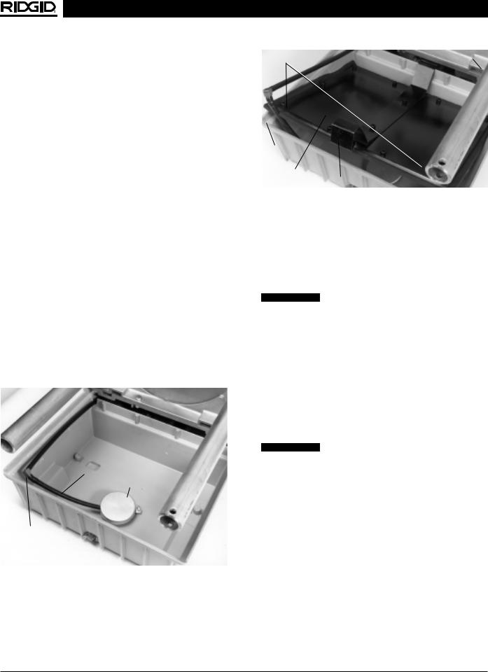
Installing No. 1460 Oil Pan Cover
NOTE! No. 1460 Oil Pan Cover installs in machine oil reservoir and prevents oil spill during transportation. No. 1460 is shipped with No. 1406 Folding Wheel Stand and is available as an accessory.
1.With oil reservoir drained, disconnect filter and oil line.
2.Attach elbow fitting and oil line extension to existing oil line (Figure 5A).
3.Reattach oil line to filter and the filter to reservoir base.
4.Install oil pan cover with oil line positioned as in
Figure 5B.
5.Set chip pan in place and machine is ready for transport.
NOTE! Chip pan will not lock into position. This is a reminder that the oil pan cover is installed.
Line Extension
Oil Filter
Elbow Fitting
Figure 5A – No. 1460 Oil Pan Cover
Push |
Rear Latch |
Oil Line
Notch
Oil Pan |
|
Cover |
Front Latch |
Figure 5B – No. 1460 Oil Pan Cover
Mounting Machine To Bench
1.If a stand is not used, the machine should be mounted to a stable bench. To mount the unit on a bench, use four (4) 5/16″ bolts in holes provided at each corner of machine base. Base dimensions are shown in Figure 2.
 WARNING Failure to mount the threading machine to a stable stand or bench may result in tipping and serious injury.
Transporting Machine with
No. 1406 Stand
1.Install 1460 Oil Pan Cover to prevent oil spillage.
2.For ease of transporting, turn hand crank counterclockwise and fold stand into a compact package.
3.Lift handles (front and rear) and skid bars are provided for transportation on stairways, over rough terrain and in and out of trucks, vans and station wagons.
 WARNING Use two persons on stairs.
4.The front handle is for control on stairs and wheelbarrow like operation.
5.The rear handle is for an assist on stairs, lifting in and out of vehicles and movement over flat surfaces in the operational position.
Transporting Machine with a Tow Motor, Material Lift or Crane
1.Place tow motor forks below base of machine and above cabinet or tray.
2.Loop a sling over a 2″ piece of pipe as shown in Figure 6 and lift machine with a lift or crane.
3.Place a sling around machine and top stand rails and lift machine with a material lift or crane.
Ridge Tool Company |
7 |
1822-I Pipe and Bolt Threading Machine
CAUTION DO NOT use a sling through the spindle tube
only.
Figure 6 – Sling Transportation
Machine Inspection
 WARNING
To prevent serious injury, inspect your Threading Machine. The following inspection procedures should be performed on a daily basis:
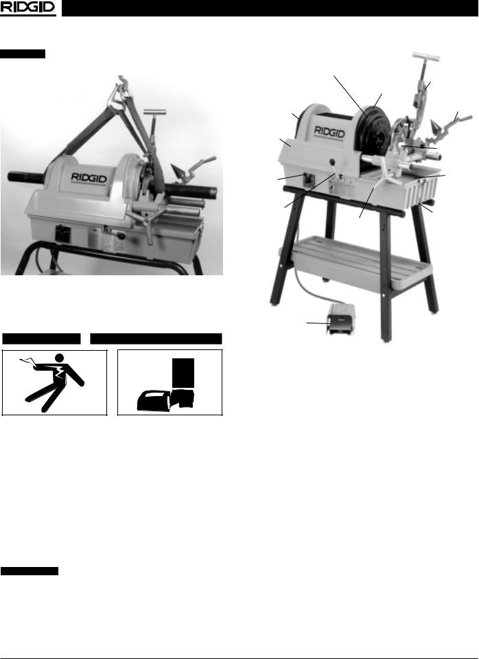
1.Make sure threading machine is unplugged and the control switch is set to the OFF position (Figure 7).
2.Clean the chuck jaws with a wire brush.
3.Inspect the jaws for excessive wear or damaged teeth. Refer to the Maintenance Instructions if they need to be replaced.
4.Make sure the foot switch is present and attached to the Threading Machine (Figure 7).
 WARNING Do not operate the Threading Machine without a foot switch.
5.Inspect the power cord and plug for damage. If the plug has been modified, is missing the grounding pin, or if the cord is damaged, do not use the Threading Machine until the cord has been replaced.
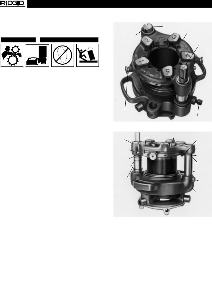
RIDGID Center-Lock Chuck
Rear Centering/Front Gripping
No. 364 Cutter
Front Cover
No. 344
Reamer
Rear Cover
Top Cover
Self-Opening
Die Head
Control |
Chip Pan |
Switch |
|
Transmission
Lever
Drain Plug
Handwheel
Foot Switch
Figure 7 – 1822-I Threading Machine
6.Inspect the Threading Machine for any broken, missing, misaligned or binding parts as well as any other conditions which may affect the safe and normal operation of the machine. If any of these conditions are present, do not use the Threading Machine until any problem has been repaired.
7.Lubricate the Threading Machine if necessary according to the Maintenance Instructions.
8.Use tools and accessories that are designed for your Threading Machine and meet the needs of your application. The correct tools and accessories allow you to do the job successfully and safely. Accessories designed for use with other equipment may be hazardous when used with this Threading Machine.
9.Clean any oil, grease or dirt from all handles and controls. This reduces the risk of injury due to a tool or control slipping from your grip.
10.Inspect the cutting edges of your tools and dies. If necessary, have them replaced prior to using the Threading Machine. Dull or damaged cutting tools and dies can lead to binding, tool breakage and poor quality threads.
8 |
Ridge Tool Company |
1822-I Pipe and Bolt Threading Machine
NOTE! High speed dies are recommended for use with this machine when threading 1″ - 2″ pipe at 45 RPM. Because of its high speed, alloy dies will wear quickly and produce poor quality threads.
11.Clean metal shavings and other debris from the chip tray of the Threading Machine. Check the level and quality of the thread cutting oil. Replace or add oil if necessary. Reservoir in the base will hold approximately one (1) gallon of thread cutting oil.
NOTE! Thread cutting oil lubricates and cools the threads during the threading operation. A dirty or poor grade cutting oil can result in poor thread quality.
NOTE! For improved thread quality use RIDGID Stainless Steel Oil and thread at 16 RPM.
NOTE! To drain dirty oil and properly maintain the oil system, refer to the “Maintenance Instructions”.
Machine and Work Area Set-Up
 WARNING
To prevent serious injury, proper set-up of the machine and work area is required. The following procedures should be followed to set-up the machine.
1.Locate a work area that has the following:
•Adequate lighting
•No flammable liquids, vapors or dust that may ignite.
•Grounded electrical outlet
•Clear path to the electrical outlet that does not contain any sources of heat or oil, sharp edges or moving parts that may damage electrical cord.
•Dry place for machine and operator. Do not use the machine while standing in water.
•Level ground
2.Clean up the work area prior to setting up any equipment. Always wipe up any oil that may have splashed or dripped from the machine to prevent slips and falls.
3.If the workpiece extends more than four (4) feet beyond the Threading Machine, use one or more pipe stands to prevent tipping and the oscillation of the pipe.
4.If the workpiece extends beyond the Threading Machine, set-up guards or barricades to create a minimum of three (3) feet of clearance around the Threading Machine and workpiece. This “safety zone”
prevents others from accidentally contacting the machine or workpiece and either causing the equipment to tip or becoming entangled in the rotating parts.
5.If mounted on a 1406 Folding Wheel Stand, make sure 1460 Oil Pan Cover is removed.
6.If necessary, fill the reservoir with RIDGID Thread Cutting Oil.
7.Make sure OPEN/OFF/CLOSE switch is in the OFF position.
8.Position the foot switch so that the operator can safely control the machine, tools and workpiece. It should allow the operator to do the following:
•Stand facing the directional switch.
•Use the foot switch with his left foot.
•Have convenient access to the directional switch and tools without reaching across the machine.
Machine is designed for one person operation.
9.Plug the threading machine into the electrical outlet making sure to position the power cord along the clear path selected earlier. If the power cord does not reach the outlet, use an extension cord in good condition.
 WARNING To avoid electrical shock and electrical fires, never use an extension cord that is damaged or does not meet the following requirements:
•The cord has a three-prong plug similar to shown in Electrical Safety section.
•The cord is rated as “W” or “W-A” if being used outdoors.
•The cord has sufficient wire thickness (14 AWG below 25’/12 AWG 25’-50’). If the wire thickness is too small, the cord may overheat, melting the cord’s insulation or causing nearby objects to ignite.
 WARNING To reduce risk of electrical shock, keep all electrical connections dry and off the ground. Do not touch plug with wet hands.
10.Check the Threading Machine to insure it is operating properly.
•Flip the control switch to CLOSE. Press and release the foot switch. Check that the Threading Machine rotates in a counterclockwise direction as you are facing the front chuck and that the jaws close down toward center. Have the Threading Machine serviced if it rotates in the wrong direction or if the foot switch does not control its stopping or starting.
Ridge Tool Company |
9 |
1822-I Pipe and Bolt Threading Machine
•Depress and hold the foot switch. Inspect the moving parts for misalignment, binding, odd noises or any other unusual conditions that may affect the safe and normal operation of the machine. If such conditions are present, have the machine serviced.
•Flip the control switch to OPEN. Press and release the foot switch. Check that the Threading Machine rotates in a clockwise direction as you are facing the chuck.
•Release the foot switch and flip the control switch to OFF.
Operation Using
Machine-Mounted Tools
 WARNING
Do not wear gloves or loose clothing when operating Threading Machine. Keep sleeves and jackets buttoned. Do not reach across the machine, pipe, or inside chuck openings.
Do not use this Threading Machine if the foot switch is broken or missing. Always wear eye protection to protect eyes from dirt and other foreign objects.
Keep hands away from rotating pipe and fittings. Stop the machine before wiping pipe threads or screwing on fittings. Allow the machine to come to a complete stop before touching the pipe.
Do not use this machine to “make-on” or “break off” fittings. This practice is not an intended use of this Threading Machine.
Installing and Chucking Pipe In
Threading Machine:
1.Check to insure the cutter, reamer and die head are in the UP position.
2.Mark the pipe at the desired length if it is being cut to length.
3.Place speed selector in 45 RPM position.
4.Insert the pipe into the Threading Machine so that the end to be worked or the cutting mark is located a sufficient distance to complete desired operation.
5.Insert workpieces less than 2 feet long from the front of the machine. Insert longer pipes through either end so that the longer section extends out the rear of the Threading Machine.
 WARNING To avoid equipment tip-overs, position the pipe supports under the workpiece.
6.Place the control switch in the CLOSE position and step on machine’s foot switch. The machine will automatically center and grip the pipe or bolt stock.
NOTE! If pipe is chucked off-center, run the machine in the OPEN switch position to release pipe and rechuck. Slight off-center chucking can be corrected with a normal ream or cut-off operation.
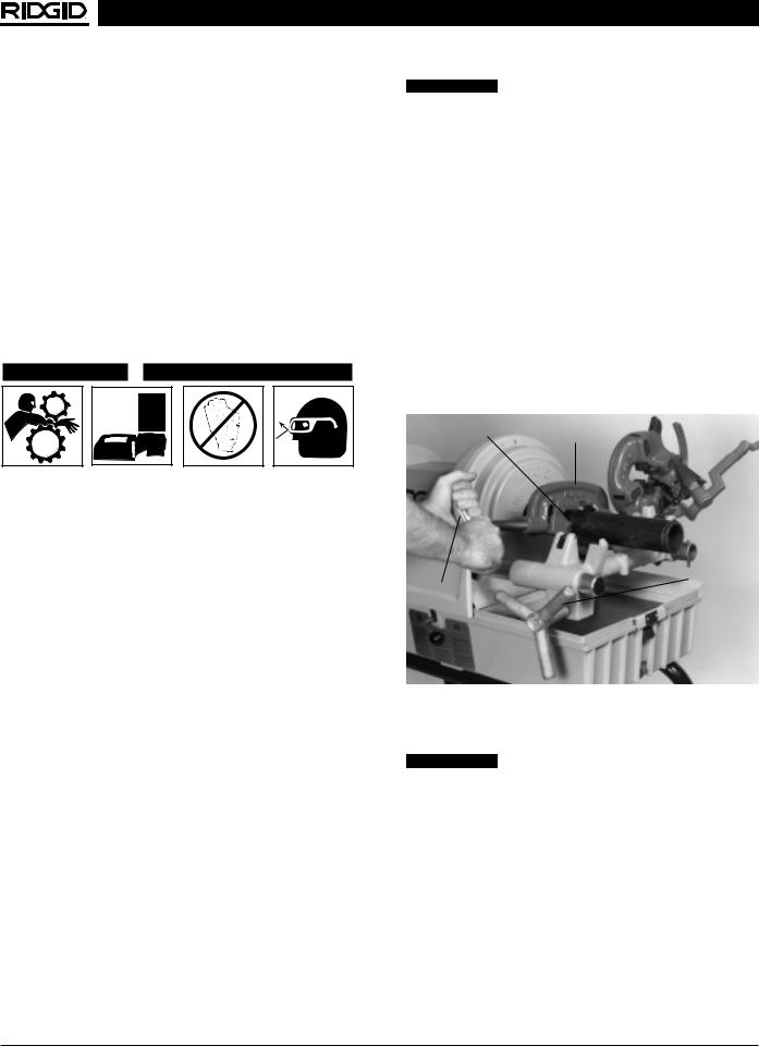
Cutting Pipe with No. 364 Cutter
1.Swing reamer and die head to UP position.
2.Move pipe cutter DOWN onto pipe and move carriage with handwheel to line up cutter wheel with mark on pipe.
3.Tighten cutter feed screw handle on pipe keeping wheel aligned with the pipe (Figure 8).
View Angle |
Cutter |
|
Handwheel
Feedscrew
Handle
Figure 8 – Cutting Pipe with 364 Cutter
4. Assume the correct operating posture.
 WARNING This will allow you to maintain proper balance and to safely keep control of the machine and tools.
•Be sure you can quickly remove your foot from the foot switch.
•Stand facing the control switch.
•Be sure you have convenient access to control switch and tools.
•Do not reach across the machine or workpiece.
5.Grasp the pipe cutter’s feedscrew handle with both hands.
6.Depress and hold down the foot switch with the left foot.
10 |
Ridge Tool Company |
1822-I Pipe and Bolt Threading Machine
7.Tighten the feedscrew handle slowly and continuously until the pipe is cut. Do not force the cutter into the workpiece.
8.Release the foot switch and remove your foot from the housing.
9.Swing pipe cutter back to the UP position.
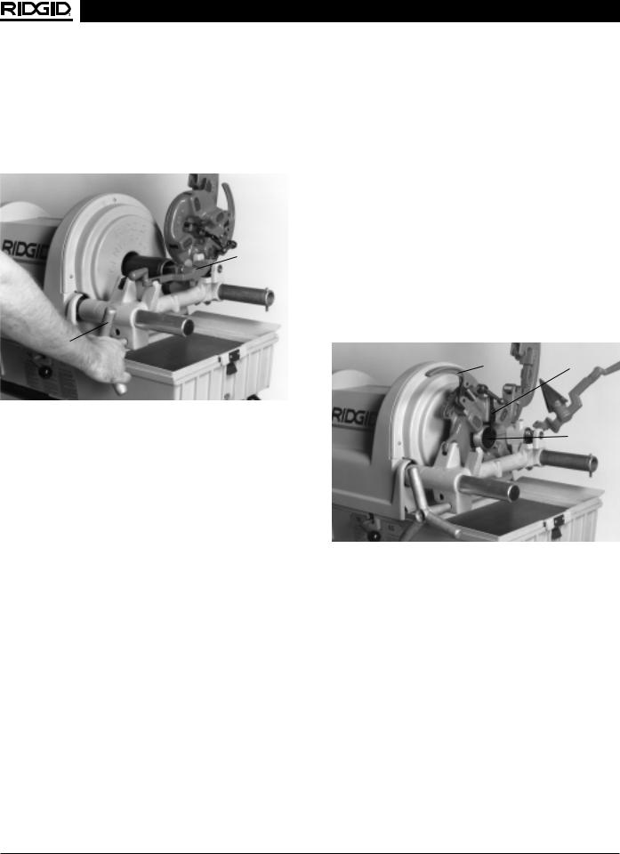
Reamer
Handwheel
Figure 9 – Reaming with 344 Reamer
Reaming Pipe with No. 344 Reamer
1.Move reamer arm into DOWN position.
2.Depress and hold the foot switch down with left foot and feed carriage handwheel towards pipe.
3.Position reamer into pipe and complete reaming by exerting slight pressure on handwheel (Figure 9).
4.Retract reamer and return reamer to UP position.
5.Release foot switch and remove your foot from the housing.
Threading Pipe or Rod with Self-Opening, Quick-Opening, or Semi-Automatic
Die Head
1.Install die set. Refer to die installation procedure. Set die head to proper size.
2.Swing cutter and reamer to UP position.
3.Swing die head to DOWN position with throwout lever set to CLOSE position.
4.Check gear shift lever and place it in the proper speed shown in the speed selection chart.
Speed Selection Chart
Size/Material |
Recommended RPM |
1/8″ – 2″ Pipe |
45 |
1/4″ – 1″ Bolt |
45 |
High Torque Applications |
16 |
• Stainless Steel |
|
• Bolt Above 1″ |
|
Low Voltage Conditions |
16 |
|
|
NOTE! 20 amp circuits with good line voltage and minimal extension cords will allow threading 2″ pipe at 45 RPM. If the machine stalls due to low voltage, complete the thread at 16 RPM. On 15 amp circuits, 11/2″ – 2″ pipe must be threaded at 16 RPM.
NOTE! Failure to select proper speed may result in motor stalling under low voltage conditions.
5.Turn carriage handwheel to bring dies against end of pipe. Slight pressure on handwheel will start dies
(Figure 10).
Throwout |
Self-Opening |
Lever |
Die Head |
Trigger
Assembly
Handwheel 
Figure 10 – Threading Pipe with No. 815A Die Head
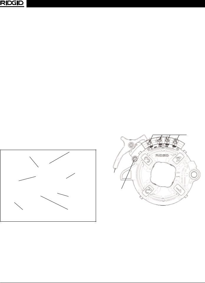
6.Self-Opening 815A Die Head (Figure 11) – When die head trigger contacts end of pipe, throwout lever is automatically opened.
NOTE! For 1/2″ to 2″ pipe, die head will open automatically when proper length of thread has been cut. For 1/8″, 1/4″ and 3/8″ pipe, die head must be opened manually.
Quick-Opening 811A Die Head (Figure 12) – When the end of pipe being threaded is flush with the end of the Number 1 die, rotate throwout lever to OPEN position, retracting dies.
Semi-Automatic Die Head (Figure 13) – When the end of the pipe being threaded is flush with the end of the Number 1 Die, hit the handle to release the dies from the pipe.
7. Turn carriage handwheel to back die head off pipe.
Ridge Tool Company |
11 |

1822-I Pipe and Bolt Threading Machine
8.Move die head to UP position.
9.Release foot switch and remove your foot from the housing.
Removing Pipe From The Threading
Machine
1.Turn the control switch to the OPEN position. Depress foot switch and machine will release the pipe.
2.Release foot switch and turn control switch to the OFF position.
 WARNING Never reach inside chuck cover while machine is connected to a power source. Fingers can be crushed.
3.Slide the workpiece out of the Threading Machine, keeping a firm grip on the workpiece as it clears the Threading Machine.
 WARNING To avoid injury from falling parts or equipment tip-overs when handling long workpieces, make sure that the end farthest from the Threading Machine is supported prior to removal.
4.Clean up any oil spills or splatter on the ground surrounding the Threading Machine.
Installing Dies In Self-Opening Die Head
(Right Hand Only)
The No. 815A Self-Opening Die Head (Figure 10) for right hand threads requires four sets of dies to thread pipe ranging from 1/8″ through 2″. One set of dies is required for each of the following pipe size ranges: (1/8″), (1/4″ and 3/8″), (1/2″ and 3/4″) and (1″ through 2″). Bolt threading requires a separate set of dies for each bolt size.
NOTE! High speed dies are recommended for threading 1″ to 2″ pipe at 45 RPM.
1.Place self-opening die head on bench in vertical position.
2.Make sure trigger assembly is released.
3.Loosen clamp lever approximately six full turns.
4.Pull lock screw out of slot under size bar so that roll pin in lock screw will bypass slot. Position size bar so that index line on lock screw is aligned with the end of REMOVE DIES position.
5.Lay die head down with numbers up.
6.Remove dies from die head.
7.Insert new dies to mark on side of dies. Numbers 1 through 4 on the dies must match numbers on the die head.
8.Move throwout lever back to lock in dies.
9.With head in vertical position, rotate cam plate until roll pin on lock screw can be positioned in slot under size bar. In this position dies will lock in die head. Make sure roll pin points toward end of size bar marked REMOVE DIES.
10.Adjust die head size bar until index line on lock screw is aligned with proper size mark on size bar.
Roll Pin |
Size Bar |
|
|
Index Line |
|
Lock Screw |
|
|
Clamp |
|
Lever |
Throwout |
|
Lever |
|
|
Trigger |
|
Assembly |
Figure 11 – Universal Self-Opening Die Head
11.Tighten clamp lever.
12.If oversize or undersize threads are required, set the index line in direction of OVER or UNDER size mark on size bar.
NOTE! When left hand threading the UNDER/OVER positions are reversed.
Installing Dies In Quick-Opening Die
Head (Right and Left Hand)
The No. 811A Universal Die Head (Figure 11) for right hand threads requires four sets of dies to thread pipe ranging from 1/8″ through 2″. One set of dies is required for each of the following pipe size ranges: (1/8″), (1/4″ and 3/8″), (1/2″ and 3/4″) and (1″ through 2″). Bolt threading requires a separate set of dies for each bolt size. No bolt dies are available for left hand universal die heads.
12 |
Ridge Tool Company |
1822-I Pipe and Bolt Threading Machine
NOTE! High speed dies are recommended for threading 1″ to 2″ pipe at 45 RPM.
1.Lay die head on bench with numbers face up.
2.Flip throwout lever to OPEN position.
3.Loosen clamp lever approximately three turns.
4.Lift tongue of clamp washer up and out of slot under size bar. Slide throwout lever all the way to end of slot in the change die direction indicated on cam plate.
5.Remove dies from die head.
6.Insert new dies to mark on side of dies. Numbers 1 through 4 on the dies must match numbers on the die head.
7.Slide throwout lever back so that tongue of clamp lever washer will drop in slot under size bar.
8.Adjust die head size bar until index line on link is aligned with proper size mark on size bar. For bolt threads (of any size), align index line with bolt line on size bar.
9.Tighten clamp lever.
10.If oversize or undersize threads are required, set the index line in direction of OVER or UNDER size mark on size bar.
Washer
Index Line
|
Head |
Link |
|
Throwout |
Clamp Lever |
Lever |
|
|
Size Bar |
Figure 12 – Universal Quick-Opening Die Head
Installing Die In Model 816/817 Die Heads
The Semi-Automatic Die Head (Figure 13) for right hand threads requires four sets of dies to thread pipe ranging from 1/8″ through 2″. One set of dies is required for each of the following size ranges: (1/8″), (1/4″ and 3/8″), (1/2″ and 3/4″) and (1″ through 2″). Bolt threading requires a separate set of dies for each bolt size.
1. Depress handle and rotate so that cam plate rests
(Figure 13 – Model 816/817 Die Head) against the plunger knob (as shown).
2.Lay the die head down flat on a table or bench with the numbers facing up.
3.Pull up on the plunger knob and rotate the handle counter-clockwise all the way (to the left).
4.Select the correct dies for the size desired (size marked on the back end or face of the dies).
5.Numbers on the dies must correspond with those on the die head slots. Insert dies to the line marked on the dies – numbered edge up.
6.Rotate the handle clockwise (to the right) so that the plunger knob pops back down flush against the die head.
7.To set or adjust for desired size, loosen the screw for the desired size stop, move the block to the right to make it Under-Sized and to the left to make it OverSized. When setting blocks for new dies, start with the position block on the middle mark and adjust from there.
Size Stop
Handle
Plunger Knob
Figure 13 – Semi-Automatic Die Head
Checking Thread Length
(Figure 14)
1.Thread is cut to proper length when end of pipe is flush with edge of dies (Figure 14A).
2.Die Head is adjustable to obtain proper thread diameter. If possible, threads should be checked with a thread ring gage (Figure 14B). A proper thread is cut when end of pipe is plus or minus one turn of being flush with face of ring gage.
Ridge Tool Company |
13 |

1822-I Pipe and Bolt Threading Machine
|
|
Die |
|
|
Die |
|
|
|
|
|
|
|
|
W |
Die Flush |
|
W |
||||||
|
|
With End |
|
||||||||
|
|
|
|
|
|
|
|
|
|||
|
|
|
of Pipe |
|
|
|
|
|
|
||
|
|
|
Pipe |
|
|
|
|
|
|
||
|
|
|
|
Pipe |
|
|
|
|
|
|
|
Starting to Cut Thread |
|
Completed Thread |
|||||||||
|
|
A - Full Width Die Thread |
|||||||||
Thin Ring |
|
|
|
|
|
|
|
|
|
||
Gage |
|
|
|
|
|
|
|
|
|
||
|
|
D |
|
|
D |
|
|
D |
|||
|
|
Flush |
|
|
|
|
|
|
|
|
|
|
|
One Turn Large |
|
|
|
|
|
|
|||
|
|
|
One Turn Small |
||||||||
|
|
(Basic Size) |
(Maximum Size) |
|
(Minimum Size) |
||||||
B - Checking Threads Within Pipe Gage
Figure 14 – Checking Thread Length
No. 819 Nipple Chuck and
No. 839 Adapter Kit
Installation
1.The machine utilizes No. 819 Nipple Chuck and existing size adapter. Mounting requires a No. 839 Adapter Kit (Figure 15).
2.Assemble the 819 nipple chuck/839 Adapter Kit as described in the instructions provided with the kits.
3.Turn control switch to the OPEN position and depress foot switch to fully open chuck.
NOTE! Make sure that special front retainer plate is installed to allow for use of 819 and 839 adapter.
4.Insert the adapted No. 819 Nipple Chuck, tube end first, into chuck of No. 1822-I Threading Machine. Rotate assembly until key on 839 slides into notch.
No. 819 Nipple Chuck
|
Wrench |
|
Pipe |
|
Adapter |
Insert |
|
Pin |
|
Retaining |
Front Retainer Plate |
Rings |
|
Figure 15 – No. 819 and No. 839 Assembly
Nipple Threading Procedure
1.Ream, thread and cut pipe to desired length using standard procedures.
2.Install No. 819 and 839 adapter (Figure 16).
3.Position insert with small end toward adapter for 1/8″ to 3/4″ pipe, large end toward adapter for 1″ pipe and no insert for pipe 11/4″ and up.
4.Install proper adapter and tighten with wrench.
 WARNING Remove wrench before starting machine.
5.Screw nipple into adapter, ream and thread other end (Figure 17). Insert wrench into collar and release nipple.
Nipple Chuck
Insert Wrench
Adapter
Figure 16 – Installation Insert and Adapters
Nipple
Wrench
Release
Collar
Figure 17 – Installing and Releasing Nipples
14 |
Ridge Tool Company |
1822-I Pipe and Bolt Threading Machine
Operation Instructions
Using Geared Threaders
 WARNING
Do not wear gloves or loose clothing when operating Threading Machine. Keep sleeves and jackets buttoned. Do not reach across the machine or geared threader.
Do not use this Threading Machine if the foot switch is broken or missing. Always wear eye protection to protect eyes from dirt and other foreign objects.
To prevent tipping, proper set-up of the Threading Machine and Geared Threader is required. Follow instructions carefully.
No. 141 Geared Threader weighs 95 pounds. Two
(2) persons should be used to lift this threader.
Adjusting No. 141 Geared Threader
1.With the No. 141 Geared Threader on floor and drive shaft facing up, pull two cam plate knobs and rotate cam plate to desired size. Locating pins will drop into holes in selector plate.
Thread Size Adjustment
1.For standard thread depth, hold workholder stationary and rotate gear case by hand until standard line on pinion sleeve is flush with bottom of die head or the standard line on guide post is flush with top of die head (Figure 18).
2.For oversized threads, rotate gear case until the 2T Over Line on guide post is flush with top of die head.
3.For undersized threads, rotate gear case until the 2T Under Line on guide post is flush with top of die head.
|
Guide Post |
Reference |
Head |
|
|
Lines (3) |
|
Drive Shaft
Cam Plate |
|
Knob (2) |
Clamp Screw |
|
Figure 18 – No. 141 Geared Threader with Drive Shaft Up
|
Selector |
Die (Set of 5) |
Guide |
|
Die Head |
Plate |
|||
|
Block |
|||
|
|
|||
Stop |
|
|
2T Under |
|
|
|
Line |
||
Screw |
|
|
||
|
|
Standard |
||
|
|
|
||
Red Stop |
|
|
LIne |
|
Line |
|
|
2T Over |
|
|
|
|
||
Standard |
|
|
Line |
|
Line |
|
|
Guide Post |
|
|
|
|
||
Pinion |
|
|
|
|
Sleeve |
|
|
Screw |
|
|
|
|
Gear Case |
Figure 19 – No. 141 Geared Threader showing Pinion Sleeve and Guide Post Reference Lines
Indexing Guide Post For Straight Or
Tapered Threads
(Figure 19)
1.At a standard size thread setting, remove set screw at base of guide post and pull post through die head.
2.For tapered threads, insert guide post with the diagonal slot inward through die head. Guide block will engage diagonal slot and post will rotate toward gear case.
Ridge Tool Company |
15 |

1822-I Pipe and Bolt Threading Machine
3.For straight threads, insert guide post with straight slot inward through die head to the gear case.
4.With guide block in diagonal/straight slot, replace set screw.
Changing Dies
(Figure 19)
1.Remove stop screw.
2.Pull knobs and rotate cam plate to “CD” mark.
3.Remove Die #1 and insert new Die #1 (repeat).
4.Rotate cam plate to size.
5.Replace stop screw.
NOTE! If it becomes necessary to remove or replace guide block, the stamped number E-1997 on guide block must be AGAINST selector plate. If number is visible, you will cut an UNDERSIZED thread.
Operating No. 141 Geared Threader
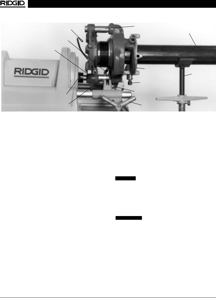
Installing No. 141 Geared Threader
(Figure 20)
Mounting No. 141 Geared Threader on machine requires a No. 241 Carriage Mount Kit. The kit includes a carriage saddle, carriage connecting link, reversing drive shaft and oil routing manifold. The control switch must be in the CLOSE position for No. 141 Geared Threader operation.
1.Remove cutter, die head and reamer from machine.
2.Install carriage saddle.
3.Install oil manifold (see No. 821 Blade Cutter).
4.From the front of machine, install drive shaft through spindle tube up to front cover. A counter-clockwise rotation is necessary for drive shaft installation or removal.
CAUTION Jaws must be fully open to install or remove
drive shaft.
CAUTION DO NOT install or remove drive shaft through rear chuck. Rear centering fingers could be bent/broken.
5.With carriage away from chuck, carefully place No. 141 Geared Threader on the carriage saddle and install connecting link.
6.From machine rear, rotate and push drive shaft onto square shaft of No. 141. Tighten set screws. Tighten connecting link set screw.
7.With No. 141 set at standard line, rotate carriage handwheel until assembly is 1″ from front chuck cover.
Threading 21/2″ to 4″ Pipe (45 RPM)
1.Adjust No. 141 Geared Threader and install on 1822-I Threading Machine.
2.Support pipe with a pipe stand.
3.Insert pipe into the throat of dies and tighten workholder and clamp screw.
4.Direct oil spout at dies and place oil manifold lever in required position.
5.Place control switch in the CLOSE position and with transmission lever in the 45 RPM position, depress foot switch.
6.Thread until the red stop line appears on pinion sleeve (reference the guide post markings for oversized or undersized threads).
7.To back off threader, place control switch in the OPEN position and depress foot switch.
8.After 1/4 turn of pipe, stop machine, pull cam plate knobs and rotate cam plate toward “CD” mark of die head.
9.Loosen clamp screw and open workholder. Remove the pipe.
10.Depress foot switch and reset No. 141 to standard line.
CAUTION If threaded barrel becomes disengaged from workholder, it must be re-engaged by hand on a workbench. DO NOT use power.
NOTE! If a ring gauge is not available, a fitting can be used. This fitting should be representative of those being used on the job. The pipe thread should be cut to obtain 2 to 3 turns hand tight engagement with fitting. If pipe thread is not made to the proper diameter, the index line should be moved in the direction of the OVER or UNDER size mark on size bar. (Refer to “Installing Dies In Die Heads”).
16 |
Ridge Tool Company |
1822-I Pipe and Bolt Threading Machine
Oil Spout |
Guide Post |
Pipe
Connecting
Link
Oil Manifold/Lever
(Hidden)
|
Workholder |
|
VJ-99 Pipe |
|
Stand |
|
Clamp Screw |
Drive Shaft |
Carriage |
(Set Screws) |
Saddle |
Pinion Sleeve |
Handwheel |
Figure 20 – Operation of the No. 141 Geared Threader
No. 821 Blade Cutter and
No. 822 Adapter Kit
No. 821 Blade Cutter allows the machine to groove, bevel and produce square end cuts for lined pipe and other applications. Installation requires a No. 822 Adapter Kit. The kits includes a cutter attaching arm, oil supply manifold and manifold clamp/drip tray. Reference instructions with kit.
Installation of No. 821 Blade Cutter
1.Remove standard No. 364 Wheel Cutter from carriage.
2.Install attaching arm and No. 821 Blade Cutter.
3.Disconnect plastic oil supply line and metal fitting from carriage.
4.Attach metal manifold supply line to carriage, install manifold and manifold clamp/drip tray.
5.Reattach plastic oil supply line to manifold.
Cut Grooving, Beveling and Cut-Off with No. 821 Blade Cutter (45 RPM)
1.Install tool bit required for desired operation.
2.Chuck pipe and place oil supply lever in the position required to direct cutting oil to flexible oil spout.
3.Place cutter over pipe and with machine in operation, tighten cutter handle until rolls engage pipe.
4.Direct oil spout to the cutting surface and slowly turn tool feed handle.
Left Hand Machine Operation
Machine is capable of left hand operation. However, user or Authorized Service Center modification is required. Basically, front and rear jaws are inverted and oil lines are exchanged. In addition, a left hand die head must be pinned to the near side of the carriage through the hole in carriage rest.
NOTE! Left hand reaming requires an E-863 Reamer Cone.
CAUTION Both front and rear jaws must be in left hand mode as shown in Figure 21.
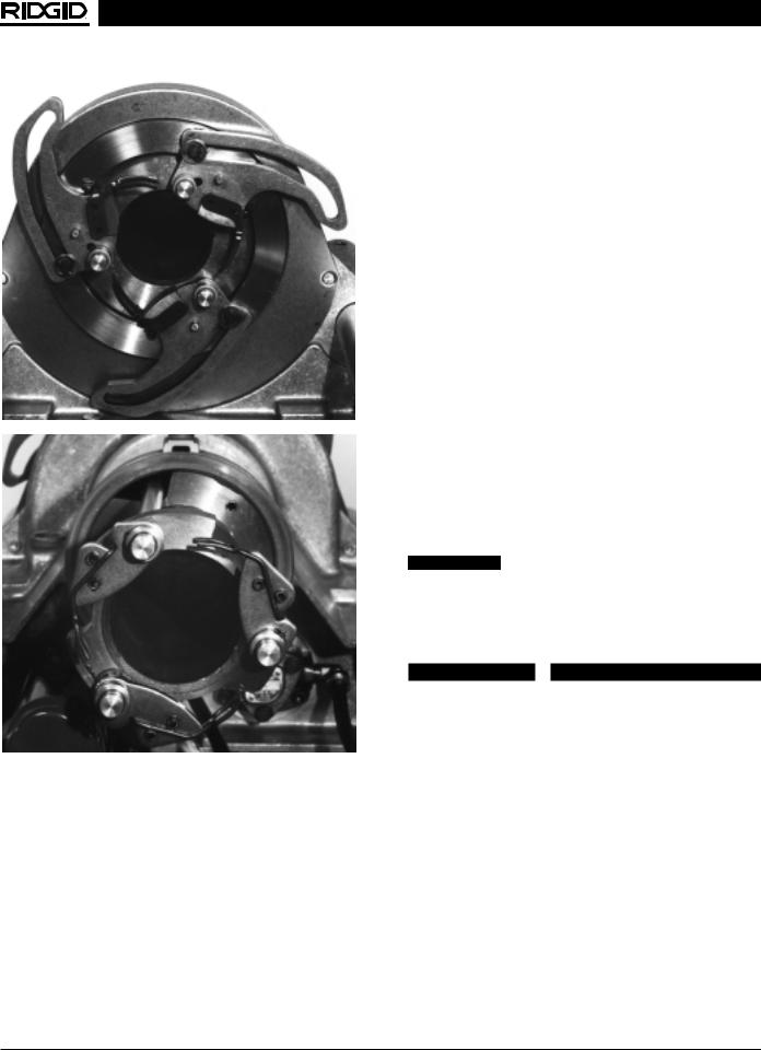
Positioning Front Jaws for Left Hand Operation
(Figure 21)
1. Run machine in the OPEN position to open jaws.
 WARNING Make sure machine is unplugged from power source before performing maintenance or making any adjustments.
2.With machine OFF and unplugged, remove front and rear covers.
3.Manually rotate front jaws toward CLOSE position and remove three E-Clips holding front retainer in place. Remove retainer and spacers.
4.Remove E-Clips and washers holding front jaws on drive pins and remove front jaws.
5.Reverse front jaws and install on drive pins and rods.
Ridge Tool Company |
17 |
1822-I Pipe and Bolt Threading Machine
Figure 21 – Machine chucking system set up for let hand operation (e-clips and retainers removed for clarity)
NOTE! Rods must be rotated 180° to match square pins of rods to locating slots in front jaws. Rear jaws can be used to hold rods in position.
6.Reinstall washers and E-Clips on drive pins. Place the spacers on rods and install retainer and E-Clips.
7.Proceed to rear jaws.
Positioning Rear Centering Jaws for Left Hand Operation
(Figure 21)
1.Rear centering jaws will be pointing outward after front jaw reversal to left hand operation.
2.Remove three E-Clips holding the rear retainer in place and remove retainer.
3.Remove spacers and rear jaws.
4.Reverse rear jaws and reinstall on square pin or rods.
5.Reinstall spacers, rear retainer and retaining clips.
NOTE! Before reinstalling machine covers make sure both front and rear jaws are in the same operating mode. (See Figure 21 for L.H. set up or Figure 24 if returning to R.H. operation.)
Oil Line Set-Up for Left Hand Operation
1.For left hand operation the oil supply line to the carriage connects to the oil pump fitting marked IN.
2.For left hand operation, the oil supply line from the oil filter connects to the oil pump fitting marked OUT.
NOTE! For right hand operation oil lines are reversed from the positions described above.
 WARNING In the left hand operating mode, the control switch positions are reversed. CLOSE becomes OPEN. OPEN becomes CLOSE.
Accessories
 WARNING
Only the following RIDGID products have been designed to function with the 1822-I Threading Machine. Other accessories designed for use with other tools may become hazardous when used on this Threading Machine. To prevent serious injury, use only the accessories listed below.
Accessories For Threading Machine
Stands: |
|
No. 1406...................... |
Folding Wheel Stand with |
|
No. 1460 Oil Pan Cover |
No. 100A ..................... |
4 legs w/tray |
No. 150A ..................... |
2 wheels w/tray |
No. 200A ..................... |
2 wheels w/enclosed cabinet |
18 |
Ridge Tool Company |
1822-I Pipe and Bolt Threading Machine
Model |
|
No. |
Description |
819 |
Nipple Chuck 1/2″ - 2″ NPT |
819 |
Nipple Chuck 1/2″ - 2″ BSPT |
839 |
Adapter Kit for No. 819 Nipple Chuck |
821 |
Blade Type Cutter |
822 |
Adapter Kit for No. 821 Blade Cutter |
141 |
4″ Geared Threader NPT |
141 |
4″ Geared Threader BSPT |
241 |
Carriage-Mount Kit for No. 141 Threader |
1460 |
Oil Pan Cover Kit |
E-863 |
L.H./R.H. Reamer Cone |
364 |
Wheel Type Cutter |
|
Conversion Kit for Plastic Coated Pipe |
|
Grooving Tool |
E-1050 |
Saran Tool for 821 |
D471 |
45° Bevel, Cut-Off Tool for 821 |
344 |
Reamer |
|
Gear Grease (1224 & 1822) |
|
|
Pipe Support Stands
No. 819 Nipple Chuck (Right Hand Only)
No. 839 Adapter Kit
Pipe Adapters..............1/8″ through 11/2″
Stud Adapters..............1/4″ through 2″ UNC
1/4″ through 11/2″ UNF
Accessories For Threading
By Close-Coupled Method
No. 241 Carriage Mount Kit
No. 141 Geared Threader… .for threading 21/2″ - 4″ pipe
Pipe Support Stand
NOTE! See Ridge Tool catalog for complete list of pipe supports, thread cutting oil and dies.
Maintenance Instructions
 WARNING
Make sure machine is unplugged from power source before performing maintenance or making any adjustment.
Oil System Maintenance
Periodic cleaning of oil reservoir and filter screens will promote proper operation of machine. Replace cutting oil when it becomes dirty or contaminated.
1.Remove and clean top chip pan screen.
2.Remove and clean secondary screen from chip pan.
3.Remove drain plug and drain cutting oil.
4.Clean oil filter screen and remove sludge built up in oil reservoir.
CAUTION DO NOT operate machine with oil filter in bottom of oil reservoir removed. This could cause chips to clog oil line and/or damage the oil pump.
NOTE! RIDGID Thread Cutting Oil produces high quality threads and maximizes die life. For information concerning its use and handling, refer to the labels on the oil containers. Disposal of the oil should be in accordance with government regulations.
Spindle Bearing Lubrication
(Figure 22)
Bearing Lubrication
Ports
Spindle Housing
Figure 22 – Spindle Bearing Lubrication
Main spindle bearing lubrication ports are located on top and at each end of the spindle housing.
Bearings are oil impregnated when manufactured and will serve to lubricate spindle until scheduled maintenance is performed.
Lubrication with 10 drops of SAE 20 Weight Nondetergent oil is recommended every six months (more often under heavy machine usage).
Front Jaw Insert and Centering Finger
Replacement
1.Run machine in the OPEN position to open jaws.
2.With machine OFF and unplugged, remove front cover.
3.Loosen screw that holds jaw insert and centering finger in place. This should allow jaw insert to separate from jaw assembly. (Figures 23A & B)
4.On a workbench, drive out top pins holding centering finger in place and install new centering finger.
NOTE! When driving pin out on workbench, do not bend centering finger.
Ridge Tool Company |
19 |

1822-I Pipe and Bolt Threading Machine
Figure 23A – Remove Jaw Insert
Figure 23B – Remove Jaw Insert
5. Reinstall jaw insert and finger, and tighten screw.
Rear Centering Finger/Jaw Replacement
1.With rear centering jaw in the OPEN position unplug machine and remove rear cover.
2.Remove three e-clips holding rear retainer in place and remove retainer. (Refer to Figure 26 Step 1.)
3.Remove spacers and rear centering jaws.
4.On a workbench, drive out pins holding centering finger in place and install new centering finger.
5.Reinstall rear jaws and spacers on rods. (Refer to Figure 24.) Locate square pin in jaw slot.
Figure 24 – Reinstall Rear Jaws and Spacers on Rods
6. Reinstall rear retainer and retaining clips.
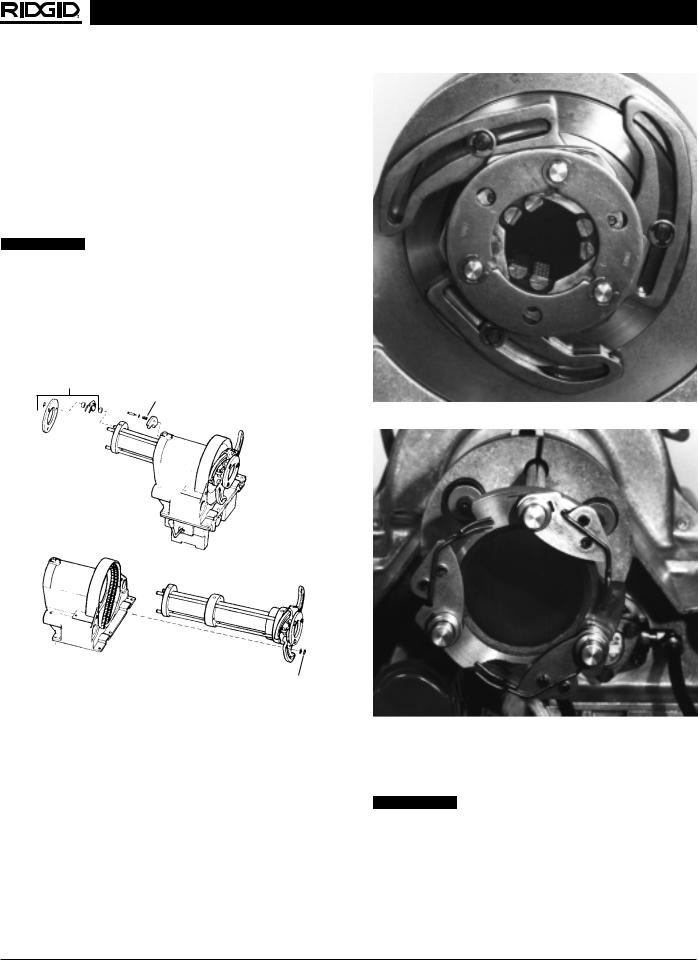
Spindle Conversion Kit for Plastic Coated Pipe
Figure 25 – PCP Kit
Spindle Assembly Removal
1.With machine OFF and unplugged, remove front and top covers.
2.Remove rear centering assembly.
3.Remove three (3) brake shoes. (Refer to Figure 26.)
4.Remove small E-clips and washers holding front jaws to drive sprocket. Slide out spindle assembly.
Spindle Assembly Installation
1.Following reverse procedure, install new spindle assembly for plastic coated pipe.
20 |
Ridge Tool Company |
1822-I Pipe and Bolt Threading Machine
2.Install the E-clips and washers on the front jaws.
3.Reassemble the three (3) brake shoes.
NOTE! Tighten shoulder bolts until they bottom out.
4.Reassemble rear centering assembly using new spacers and rear jaws supplied with the kit.
NOTE! Rear jaws must be oriented as shown for right hand threading. (Refer to Figure 27.)
5. Install top and front covers.
 WARNING Do not operate machine with covers re-
moved.
NOTE! Once the machine is fitted with the new kit to thread plastic coated pipe, it is also capable of threading steel and galvanized pipe sizes 1/2″ – 2″. If smaller sizes than 1/2″ pipe are required, the original front and rear jaw assemblies must be installed.
Step 1
Step 2
Step 3
Figure 26 – Removing Brake Shoes
Figure 27A – Jaw Orientation
Figure 27B – Jaw Orientation
Machine Storage
 WARNING Motor-driven equipment must be kept indoors or well covered in rainy weather. Store the machine in a locked area that is out of reach of children and people unfamiliar with threading machines. This machine can cause serious injury in the hands of untrained users.
Ridge Tool Company |
21 |

1822-I Pipe and Bolt Threading Machine
Service and Repair
 WARNING
Service and repair work on this Threading Machine must be performed by qualified repair personnel. Machine should be taken to a RIDGID Independent Authorized Service Center or returned to the factory. All repairs made by Ridge Tool Company service facilities are warranted against defects in material and workmanship.
 WARNING When servicing this machine, only identical replacement parts should be used. Failure to follow these instructions may create a risk of electrical shock or other serious injury.
If you have any questions regarding the service or repair of this machine, call or write to:
Ridge Tool Company
Technical Service Department
400 Clark Street
Elyria, Ohio 44035-6001
Tel: (800) 519-3456
E-mail: TechServices@ridgid.com
For name and address of your nearest Independent Authorized Service Center, contact Ridge Tool Company at (800) 519-3456 or http://www.ridgid.com
22 |
Ridge Tool Company |
 Loading...