


 Loading...
D158/D159/D160/D161/D170
DETAILED DESCRIPTIONS
MANUAL
|
D158/D159/D160/D161/D170 |
|
||
|
DETAILED DESCRIPTIONS |
|
||
|
TABLE OF CONTENTS |
|
||
1. |
OVERVIEW .................................................................................... |
|
|
1 |
|
1.1 COMPONENT LAYOUT................................................................................... |
|
|
1 |
|
1.1.1 D160/D161/D170: CIS SCANNER COMPONENT LAYOUT ................ |
3 |
||
|
1.1.2 D158/D159: CCD SCANNER COMPONENT LAYOUT ........................ |
3 |
||
|
1.2 PAPER PATH ................................................................................................... |
|
|
4 |
|
1.3 DRIVE LAYOUT................................................................................................ |
|
|
5 |
2. |
BOARD STRUCTURE.................................................................... |
|
|
7 |
|
2.1 BLOCK DIAGRAM............................................................................................ |
|
|
7 |
|
BICU (Base Engine and Image Control Unit) ............................................ |
|
8 |
|
|
2.2 SBU (SENSOR BOARD UNIT) ........................................................................ |
|
|
8 |
3. |
COPY PROCESS OVERVIEW ....................................................... |
|
|
9 |
4. |
SCANNING D158/D159................................................................ |
|
|
11 |
|
4.1 OVERVIEW..................................................................................................... |
|
|
11 |
|
4.2 SCANNER DRIVE .......................................................................................... |
|
|
12 |
|
4.3 ORIGINAL SIZE DETECTION IN PLATEN MODE ....................................... |
|
13 |
|
|
4.4 ANTI-CONDENSATION HEATER |
................................................................. |
|
14 |
5. |
SCANNING D160/D161/D170 ...................................................... |
|
|
15 |
|
5.1 OVERVIEW..................................................................................................... |
|
|
15 |
|
5.2 SCANNER DRIVE .......................................................................................... |
|
|
16 |
6. |
LASER EXPOSURE..................................................................... |
|
|
18 |
|
6.1 OVERVIEW..................................................................................................... |
|
|
18 |
|
6.2 AUTO POWER CONTROL (APC) |
................................................................. |
|
19 |
|
6.3 LD SAFETY SWITCH..................................................................................... |
|
|
20 |
7. |
PHOTOCONDUCTOR UNIT (PCU).............................................. |
|
21 |
|
|
7.1 OVERVIEW..................................................................................................... |
|
|
21 |
|
7.2 DRIVE ............................................................................................................. |
|
|
23 |
8. |
DRUM CHARGE .......................................................................... |
|
|
24 |
|
8.1 OVERVIEW..................................................................................................... |
|
|
24 |
|
8.2 ID SENSOR PATTERN PRODUCTION TIMING .......................................... |
|
25 |
|
|
8.3 DRUM CHARGE ROLLER CLEANING ......................................................... |
|
26 |
|
9. |
DEVELOPMENT .......................................................................... |
|
|
27 |
|
9.1 OVERVIEW..................................................................................................... |
|
|
27 |
|
9.2 DRIVE ............................................................................................................. |
|
|
28 |
Detailed Descriptions |
i |
D158/D159/D160/D161/D170 |
||
9.3 DEVELOPER MIXING.................................................................................... |
29 |
9.4 DEVELOPMENT BIAS ................................................................................... |
30 |
9.5 TONER SUPPLY ............................................................................................ |
31 |
9.5.1 TONER BOTTLE REPLENISHMENT MECHANISM........................... |
31 |
9.6 TONER SUPPLY MECHANISM .................................................................... |
32 |
9.7 TONER DENSITY CONTROL ....................................................................... |
33 |
9.7.1 OVERVIEW ........................................................................................... |
33 |
9.7.2 TONER DENSITY SENSOR INITIAL SETTING.................................. |
35 |
9.7.3 TONER CONCENTRATION MEASUREMENT ................................... |
35 |
9.7.4 VSP/VSG DETECTION......................................................................... |
35 |
9.7.5 TONER SUPPLY REFERENCE VOLTAGE (VREF) DETERMINATION |
|
36 |
|
9.7.6 TONER SUPPLY DETERMINATION................................................... |
36 |
9.7.7 TONER SUPPLY MOTOR ON TIME DETERMINATIONS ................. |
36 |
9.8 TONER SUPPLY IN ABNORMAL SENSOR CONDITIONS......................... |
38 |
9.8.1 ID SENSOR........................................................................................... |
38 |
9.8.2 TD SENSOR.......................................................................................... |
38 |
9.9 TONER NEAR END/END DETECTION AND RECOVERY.......................... |
38 |
9.9.1 TONER NEAR END DETECTION........................................................ |
38 |
9.9.2 TONER NEAR END RECOVERY ........................................................ |
39 |
9.9.3 TONER END DETECTION ................................................................... |
39 |
9.9.4 TONER END RECOVERY.................................................................... |
39 |
10.DRUM CLEANING AND TONER RECYCLING............................ |
40 |
|||
10.1 |
DRUM CLEANING.................................................................................... |
|
40 |
|
10.2 |
TONER RECYCLING ............................................................................... |
|
41 |
|
11.PAPER FEED............................................................................... |
|
42 |
||
11.1 |
OVERVIEW............................................................................................... |
|
42 |
|
11.2 |
PAPER FEED DRIVE MECHANISM ....................................................... |
43 |
||
11.3 |
PAPER FEED AND SEPARATION MECHANISM.................................. |
44 |
||
11.4 |
PAPER LIFT MECHANISM...................................................................... |
|
45 |
|
11.5 |
BY-PASS TRAY BOTTOM PLATE LIFT MECHANISM.......................... |
46 |
||
11.6 |
PAPER END DETECTION....................................................................... |
|
47 |
|
11.7 |
PAPER SIZE DETECTION ...................................................................... |
|
48 |
|
11.7.1 |
PAPER TRAY................................................................................. |
|
48 |
|
0: PUSHED, 1: NOT PUSHED .......................................................... |
|
48 |
||
11.7.2 |
BY-PASS TRAY ............................................................................. |
|
50 |
|
11.8 |
SIDE FENCES .......................................................................................... |
|
51 |
|
11.9 |
PAPER REGISTRATION ......................................................................... |
|
52 |
|
12.IMAGE TRANSFER AND PAPER SEPARATION........................ |
53 |
|||
12.1 |
OVERVIEW............................................................................................... |
|
53 |
|
12.2 |
IMAGE TRANSFER CURRENT TIMING................................................. |
54 |
||
12.3 |
TRANSFER ROLLER CLEANING ........................................................... |
55 |
||
12.4 |
PAPER SEPARATION MECHANISM...................................................... |
56 |
||
13.IMAGE FUSING AND PAPER EXIT............................................. |
57 |
|||
13.1 |
OVERVIEW............................................................................................... |
|
57 |
|
D158/D159/D160/D161/D170 |
ii |
Detailed Descriptions |
||
13.2 |
FUSING UNIT DRIVE AND RELEASE MECHANISM ............................ |
58 |
|
13.2.1 |
FUSING UNIT DRIVE .................................................................... |
58 |
|
13.2.2 |
DRIVE RELEASE MECHANISM ................................................... |
58 |
|
13.2.3 |
CONTACT/RELEASE CONTROL ................................................. |
59 |
|
13.2.4 |
DRIVE RELEASE SOLENOID....................................................... |
59 |
|
13.3 |
FUSING ENTRANCE GUIDE SHIFT....................................................... |
60 |
|
13.4 |
PRESSURE ROLLER .............................................................................. |
60 |
|
13.5 |
FUSING TEMPERATURE CONTROL..................................................... |
61 |
|
13.5.1 |
OVERVIEW .................................................................................... |
61 |
|
13.5.2 |
TEMPERATURE CONTROL ......................................................... |
62 |
|
13.6 |
OVERHEAT PROTECTION..................................................................... |
64 |
|
14.DUPLEX UNIT.............................................................................. |
65 |
|
14.1 |
OVERALL.................................................................................................. |
65 |
14.2 |
DRIVE MECHANISM................................................................................ |
66 |
14.3 |
BASIC OPERATION................................................................................. |
67 |
14.4 |
FEED IN AND EXIT MECHANISM .......................................................... |
69 |
15.ENERGY SAVER MODES OF BASIC MACHINES...................... |
70 |
|
15.1 |
OVERVIEW............................................................................................... |
70 |
15.2 |
AOF ........................................................................................................... |
71 |
15.3 |
TIMERS..................................................................................................... |
71 |
15.4 |
RECOVERY.............................................................................................. |
71 |
16.ENERGY SAVER MODES OF GDI MACHINES .......................... |
72 |
|
16.1 |
OVERVIEW............................................................................................... |
72 |
16.2 |
AOF ........................................................................................................... |
73 |
16.3 |
TIMERS..................................................................................................... |
73 |
16.4 |
RECOVERY.............................................................................................. |
73 |
17.OVERVIEW .................................................................................. |
74 |
|
18.BOARDS ...................................................................................... |
75 |
|
18.1 |
FCU ........................................................................................................... |
75 |
19.SERVICE RAM ADDRESSES...................................................... |
77 |
|
20.VIDEO DATA PATH ..................................................................... |
91 |
|
20.1 |
TRANSMISSION ...................................................................................... |
91 |
20.1.1MEMORY TRANSMISSION AND PARALLEL MEMORY
TRANSMISSION ............................................................................................ |
91 |
|
20.1.2 |
IMMEDIATE TRANSMISSION ...................................................... |
92 |
20.1.3 |
JBIG TRANSMISSION................................................................... |
92 |
20.1.4 |
ADJUSTMENTS............................................................................. |
92 |
20.2 RECEPTION ............................................................................................. |
93 |
|
21.FAX COMMUNICATION FEATURES |
.......................................... 94 |
||
21.1 |
DOCUMENT SERVER ............................................................................. |
|
94 |
21.2 |
INTERNET MAIL COMMUNICATION |
..................................................... 95 |
|
21.2.1 MAIL TRANSMISSION |
.................................................................. |
95 |
|
Detailed Descriptions |
iii |
D158/D159/D160/D161/D170 |
|
21.2.2 |
MAIL RECEPTION......................................................................... |
98 |
21.2.3 |
HANDLING MAIL RECEPTION ERRORS.................................. |
100 |
21.2.4 |
SECURE INTERNET RECEPTION............................................. |
101 |
21.2.5 TRANSFER REQUEST: REQUEST BY MAIL............................ |
101 |
|
21.2.6 E-MAIL OPTIONS (SUB TX MODE) ........................................... |
102 |
|
22.IP-FAX........................................................................................ |
106 |
|
22.1 |
WHAT IS IP-FAX? .................................................................................. |
106 |
22.2 |
T.38 PACKET FORMAT......................................................................... |
106 |
22.2.1 UDP RELATED SWITCHES........................................................ |
106 |
|
22.3 |
SETTINGS .............................................................................................. |
106 |
D158/D159/D160/D161/D170 |
iv |
Detailed Descriptions |
Component Layout
1. OVERVIEW
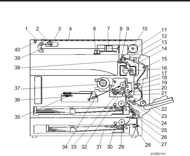
1.1 COMPONENT LAYOUT
The above illustration is the D158/D159 model.
•D170: No duplex unit
•D158/D159: CCD scanner
•D160/D161/D170: CIS scanner
Detailed Descriptions |
1 |
D158/D159/D160/D161/D170 |

Component Layout
21. Registration Roller
1. 2nd Mirror
22. Registration Sensor
2. Exposure Lamp
23. By-pass Tray
3. 1st Mirror
24. Lower Transport Roller
4. Exposure Glass
25. Upper Relay Roller
6. APS sensor (Length)
26. Relay Sensor
7. Lens Block
27. Lower Relay Roller
8. SBU
28. Vertical Transport Sensor
9. Exit Sensor
29. Paper Feed Roller
10. Scanner Motor
30. Paper End Sensor
11. Inverter Roller
31. Bottom Plate
12. Duplex Inverter Sensor
32. PCU
13. Duplex Entrance Sensor
33. Development Roller
14. Hot Roller
34. WTL
15. Upper Transport Roller
35. Polygon Mirror Motor
16. Pressure Roller
36. Laser Unit
17. OPC Drum
37. Toner Supply Bottle Holder
18. Middle Transport Roller
38. Exit Roller
19. Duplex Exit Sensor
39. 3rd Mirror
20. Image Density Sensor
40. Scanner HP Sensor
D158/D159/D160/D161/D170 |
2 |
Detailed Descriptions |
Component Layout
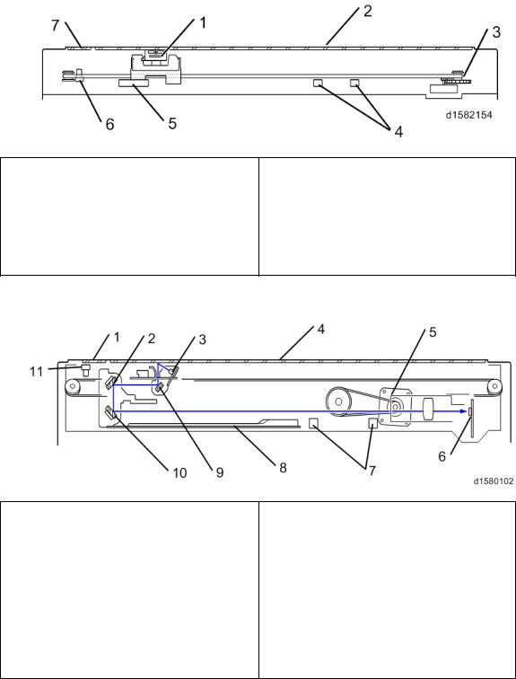
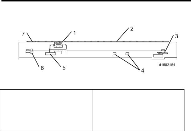
1.1.1 D160/D161/D170: CIS SCANNER COMPONENT LAYOUT
1.CIS Unit
5. APS Sensor (Width)
2. Exposure Glass
6. Scanner HP Sensor
3. Scanner Motor
7. DF Exposure Glass
4. APS Sensor (Length)
1.1.2 D158/D159: CCD SCANNER COMPONENT LAYOUT
1. DF Exposure Glass
7. APS Sensors
2. 2nd Mirror
8. Scanner Heater
3. Exposure Lamp
9. 1st Mirror
4. Exposure Glass
10.3rd Mirror
5. Scanner Motor
11. Scanner HP Sensor
6. SBU
Detailed Descriptions |
3 |
D158/D159/D160/D161/D170 |
Paper Path
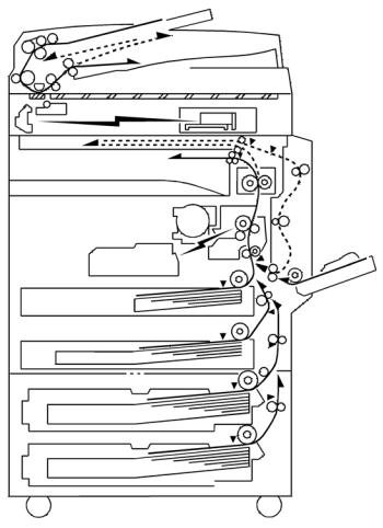
1.2 PAPER PATH
The D158, D159, D160, and D161 models have a duplex unit mounted on the right side of the machine.
All models have a by-pass tray.
D158/D159/D160/D161/D170 |
4 |
Detailed Descriptions |
Drive Layout
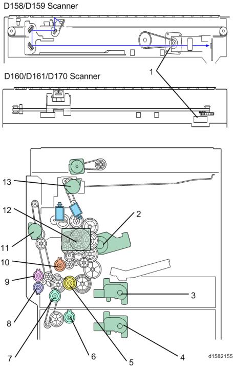
1.3 DRIVE LAYOUT
Detailed Descriptions |
5 |
D158/D159/D160/D161/D170 |
Drive Layout
1. Scanner Motor |
8. |
By-pass Paper Feed Clutch |
||
2. |
Toner Supply Motor |
9. |
By-pass Tray Lift Clutch |
|
3. |
Tray 1 Lift Motor |
10. |
Registration Clutch |
|
4. |
Tray 2Lift Motor |
11. |
Duplex Motor |
|
5. |
Upper Paper Feed Clutch |
12. |
Main Motor |
|
6. |
Lower Paper Feed Clutch |
13. Inverter Motor |
||
7. |
Relay Clutch |
|
|
|
D158/D159/D160/D161/D170 |
6 |
Detailed Descriptions |
Block Diagram
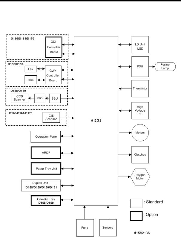
2. BOARD STRUCTURE
2.1 BLOCK DIAGRAM
Detailed Descriptions |
7 |
D158/D159/D160/D161/D170 |
SBU (Sensor Board Unit)
BICU (Base Engine and Image Control Unit)
The main board controls the following functions:
Engine sequence
Timing control for peripherals
Image processing, video control
Operation control, system control (Basic machine only)
Machine control
Drive control for the sensors, motors, and clutches of the printer and scanner
High voltage supply board control
Serial interfaces with peripherals
Fusing control
2.2SBU (SENSOR BOARD UNIT)
The SBU deals with the analog signals from the CCD and converts them into digital signals.
The SBU is attached to the CCD scanner (D158/D159).
D158/D159/D160/D161/D170 |
8 |
Detailed Descriptions |
SBU (Sensor Board Unit)
3. COPY PROCESS OVERVIEW
1. Exposure
A xenon lamp exposes the original. Light reflected from the original passes to the CCD, where it is converted into an analog data signal. This data is converted to a digital signal, processed and stored in the memory. At the time of printing, the data is retrieved and sent to the laser diode.
2. Drum Charge
In the dark, the charge roller gives a negative charge to the organic photo-conductive (OPC) drum. The charge remains on the surface of the drum because the OPC layer has a high electrical resistance in the dark.
3. Laser Exposure
The processed data scanned from the original is retrieved from the memory and transferred to the drum by a laser beam, which forms an electrical latent image on the drum surface. The amount of charge remaining as a latent image on the drum depends on the laser beam intensity, which is controlled by the BICU board.
Detailed Descriptions |
9 |
D158/D159/D160/D161/D170 |
SBU (Sensor Board Unit)
4. Development
The magnetic developer brush on the development roller comes in contact with the latent image on the drum surface. Toner particles are electrostatically attached to the areas of the drum surface where the laser reduced the negative charge on the drum.
5. ID Sensor
The laser forms a sensor pattern on the drum surface. The ID sensor measures the reflectivity of the pattern. The output signal is one of the factors used for toner supply control. Also, the ID sensor measures the reflectivity of the drum surface. The output signal is used for charge roller voltage control.
6. Image Transfer
Paper is fed to the area between the drum surface and the transfer roller at the proper time for aligning the copy paper and the developed image on the drum surface. Then, the transfer roller applies a high positive charge to the reverse side of the paper. This positive charge pulls the toner particles from the drum surface onto the paper. At the same time, the paper is electrostatically attracted to the transfer roller.
7. Paper Separation
Paper separates from the drum as a result of the electrostatic attraction between the paper and the transfer roller. The discharge plate (grounded) helps separate the paper from the drum.
8. Cleaning
The cleaning blade removes any toner remaining on the drum surface after the image transfers to the paper.
9. Quenching
The light from the quenching lamp electrically neutralizes the charge on the drum surface.
D158/D159/D160/D161/D170 |
10 |
Detailed Descriptions |
Overview
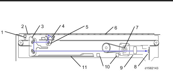
4. SCANNING D158/D159
4.1 OVERVIEW
1. |
Scanner HP sensor |
7. |
Scanner motor |
|
|
|
|
2. |
DF exposure glass |
8. |
Sensor board unit |
|
|
|
(SBU) |
|
|
|
|
3. |
2nd scanner (2nd carriage) |
9. |
Lens Block |
|
|
|
|
4. |
Scanner lamp |
10. |
APS sensor |
|
|
|
|
5. |
1st scanner (1st carriage) |
11. |
Scanner Heater |
|
|
|
|
6. |
Exposure glass |
|
|
|
|
|
|
The original on the exposure glass or ARDF exposure glass reflects the light emitted from the scanner lamp. The reflected light goes to the CCD on the sensor board by way of the 1st and 2nd scanners. The sensor board converts the CCD analog signals into digital signals.
When the original is manually placed on the exposure glass, the scanner motor pulls the 1st and 2nd scanners via mechanical linkage. The original is scanned from left to right.
When the original is fed from the optional ARDF, it is automatically transported onto the ARDF exposure glass, and to the original exit. The original does not stay on the glass; but goes to the exit. The 1st and 2nd scanners stay at their home positions.
Detailed Descriptions |
11 |
D158/D159/D160/D161/D170 |
Scanner Drive
4.2 SCANNER DRIVE
The scanner motor [A] drives the 1st scanner [B] and the 2nd scanner [C] through the scanner drive pulley, scanner drive shaft [D], and two scanner wires [E].
Book mode -
The SBU board controls the scanner drive motor. The 2nd scanner speed is half that of the 1st scanner.
In reduction or enlargement mode, the scanning speed depends on the magnification ratio. The returning speed is always the same, whether in full size or magnification mode. The image length change in the sub scan direction is done by changing the scanner motor speed. In the main scan direction it is done by image processing on the BICU board.
You can adjust the magnification in the sub-scan direction by changing the scanner motor speed with SP4-008.
ARDF mode -
The scanners always stay in their home position (the scanner HP sensor [F] detects the 1st scanner) to scan the original. The ARDF motor feeds the original through the ARDF. In reduction/enlargement mode, the image length change in the sub-scan direction is done by changing the ARDF motor speed. Magnification in the main scan direction is done in the BICU board. This is the same as for book mode.
You can adjust magnification in the sub-scan direction by changing the ARDF motor speed with SP6-017.
D158/D159/D160/D161/D170 |
12 |
Detailed Descriptions |

Original Size Detection in Platen Mode
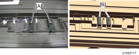
4.3 ORIGINAL SIZE DETECTION IN PLATEN MODE
There are no APS sensor (width) in the scanner unit. However, the original width can be detected by CCD. The APS sensor (length) [A] detects the original length.
The BICU board checks each sensor status when the platen cover sensor [B] is activated as it is closed. It detects the original size by the on/off signals it gets from each sensor.
If the copy is made with the platen cover fully open, the CPU determines the original size from the sensor outputs after the Start key is pressed.
Detailed Descriptions |
13 |
D158/D159/D160/D161/D170 |
Anti-Condensation Heater
4.4 ANTI-CONDENSATION HEATER
The anti-condensation heater is available as an optional unit. The anti-condensation heater prevents condensation on the mirrors. Condensation can occur when the scanner unit is, for example, moved from a cold room to a warm room. Condensation can cause abnormal images.
D158/D159/D160/D161/D170 |
14 |
Detailed Descriptions |
Overview
5. SCANNING D160/D161/D170
5.1 OVERVIEW
1. CIS unit (with carriage) |
4. |
APS sensor (length) |
|
|
|
|
|
2. |
Exposure Glass |
5. |
APS sensor (width) |
|
|
|
|
3. |
Scanner Motor |
6. |
Scanner HP sensor |
|
|
|
|
|
|
7. DF Exposure Glass |
|
CIS unit
1-ch unity-magnifying contact image sensor (RGB_LED+SLA+CMOS sensor)/capable of A3 color scanning
Bottom frame
Resin base
Upper frame
Composed of a resin base, exposure glass, and DF exposure glass
Sensor
1-ch CIS + integrated carriage + slide guide
Drive
Belt drive using a PM stepping motor
Exterior
The bottom frame (resin base) is integrated into the exterior.
APS Sensor
2 width sensors and 2 length sensors (the sensor location depends on the country of use)
Detailed Descriptions |
15 |
D158/D159/D160/D161/D170 |
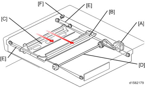
Scanner Drive
5.2 SCANNER DRIVE
Models D160, D161 and D170 are flatbed scanners using a CIS.
To scan an original, the scanner motor (A) moves the carriage on which the CIS (B) is mounted along the carrier guide rail.
The CIS can be raised or lowered using the side guide rails (C) and adjusted relative to the main scanning direction using the center guide rail (D). This is a factory adjustment; do not do this in the field.
The size of the original is detected by the APS sensors (E) on the bottom frame.
D158/D159/D160/D161/D170 |
16 |
Detailed Descriptions |
Scanner Drive
[A]: All areas except China [B]: China only
Detailed Descriptions |
17 |
D158/D159/D160/D161/D170 |
Overview
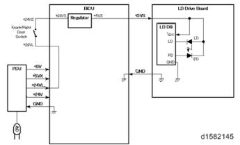
6. LASER EXPOSURE
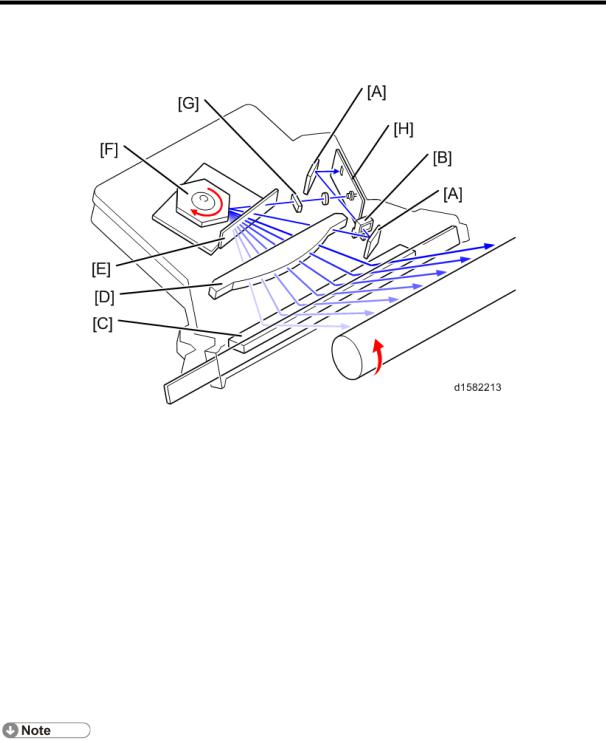
6.1 OVERVIEW
|
Name |
|
|
A |
Synchronization detector mirrors |
|
|
B |
Synchronization detector lens |
|
|
C |
Mirror |
|
|
D |
F-theta lens |
|
|
E |
Soundproof glass |
|
|
F |
Polygon Motor |
|
|
G |
Cylindrical lens |
|
|
H |
LD board |
|
|
The LD drive board controls both the laser output and laser synchronization mechanism.
The machine cuts off the power supply to the LD drive board if the front or right cover is opened.
D158/D159/D160/D161/D170 |
18 |
Detailed Descriptions |
Auto Power Control (APC)
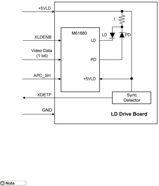
6.2 AUTO POWER CONTROL (APC)
The LD driver IC drives the laser diode. To prevent the intensity of the laser beam from changing because of the temperature, the machine monitors the current passing through the laser diode (LD). The machine adjusts the current to the laser diode by comparing it with the reference level from the reference circuit.
This auto power control is done just after the machine is turned on and during printing.
The laser diode power is adjusted on the production line.
Do not touch the variable resistors on the LD unit in the field.
Detailed Descriptions |
19 |
D158/D159/D160/D161/D170 |
LD Safety Switch
6.3 LD SAFETY SWITCH
To ensure technician and user safety and to prevent the laser beam from inadvertently switching on during servicing, safety switches are located at the front and right covers. The switches are installed on the +5VLD line through the BICU board.
When the front cover or the right cover is opened, the power supply to the laser diode is interrupted.
D158/D159/D160/D161/D170 |
20 |
Detailed Descriptions |
Overview
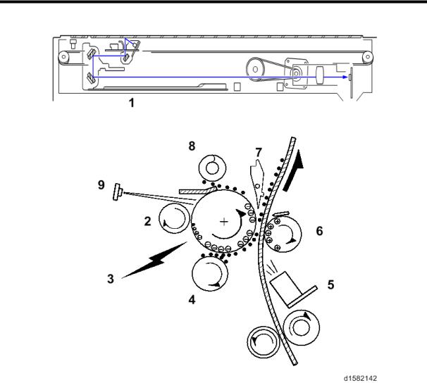
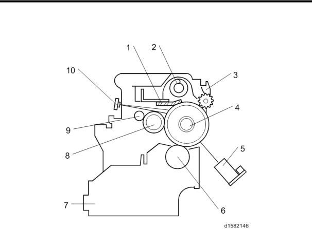
7. PHOTOCONDUCTOR UNIT (PCU)
7.1 OVERVIEW
The PCU consists of the components shown in the above illustration. An organic photoconductor (OPC) drum (diameter: 30 mm) is used in this machine.
1. |
Cleaning Blade |
6. |
Development Roller |
2. |
Toner Collection Coil |
7. |
Development Unit |
3. |
Pick-off Pawl |
8. |
Charge Roller |
4. |
OPC Drum |
9. |
Charge Roller Cleaning Brush |
5. |
ID Sensor (see note) |
10. Quenching Lamp (see note) |
|
Detailed Descriptions |
21 |
D158/D159/D160/D161/D170 |
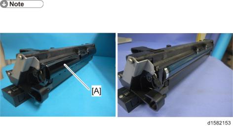
Overview
The ID sensor and quenching lamp are not included in the PCU.
The OPC drum's shutter [A] of the previous model has been removed.
D158/D159/D160/D161/D170 |
22 |
Detailed Descriptions |
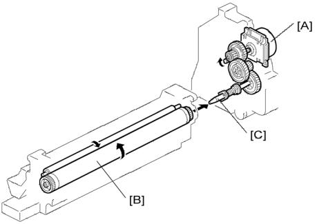
Drive
7.2 DRIVE
The main motor [A] drives the drum [B] through a series of gears and the drum drive shaft [C]. The main motor assembly includes a drive controller, which outputs a motor lock signal when the rotation speed is out of the specified range.
Detailed Descriptions |
23 |
D158/D159/D160/D161/D170 |
Overview
8. DRUM CHARGE
8.1 OVERVIEW
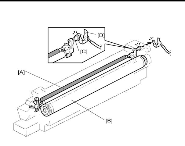
This copier uses a drum charge roller to charge the drum. The drum charge roller [A] always contacts the surface of the drum [B] to give it a negative charge of –950 V.
The high voltage supply board gives a negative charge of –1700 V to the drum charge roller through the screw [C] and terminal plate [D]. This voltage can be changed using SP2-001- 001 (Charge Roller Bias Adjust Setting (Copying)).
D158/D159/D160/D161/D170 |
24 |
Detailed Descriptions |
ID Sensor Pattern Production Timing
8.2 ID SENSOR PATTERN PRODUCTION TIMING
The ID sensor pattern is not made every page or every job.
It is only made in the following conditions:
During warm-up at power on
When the machine starts warming up from energy saver mode and the temperature is less than the target temperature as set with SP Mode.
When the machine starts warming up from energy saver mode and the machine prints more than 100 prints after generating the p-pattern.
Detailed Descriptions |
25 |
D158/D159/D160/D161/D170 |
Loading...