


A 2018d
Table of contents
 Loading...
RICOH GROUP COMPANIES
B121/B122/B123
SERVICE MANUAL
001874MIU


SERVICE MANUAL
B121/B122/B123
®
®
RICOH GROUP COMPANIES


B121/B122/B123
SERVICE MANUAL
001874MIU


A
f
r
It is the reader's responsibility when discussing the information contained
within this document to maintain a level of confidentiality that is in the best
interest of Ricoh Corporation and its member companies.
NO PART OF THIS DOCUMENT MAY BE REPRODUCED IN ANY
FASHION AND DISTRIBUTED WITHOUT THE PRIOR
PERMISSION OF RICOH CORPORATION.
ll product names, domain names or product illustrations, including
desktop images, used in this document are trademarks, registered
trademarks or the property of their respective companies.
They are used throughout this book in an informational or editorial fashion
only and for the benefit of such companies. No such use, or the use o
any trade name, or web site is intended to convey endorsement or othe
affiliation with Ricoh products.
2004 RICOH Corporation. All rights reserved.


p
t
r
g
l
y
p
WARNING
The Service Manual contains information
regarding service techniques, procedures,
rocesses and spare parts of office equipmen
distributed by Ricoh Corporation. Users of this
manual should be either service trained o
certified by successfully completing a Ricoh
Technical Training Program.
Untrained and uncertified users utilizin
information contained in this service manual to
repair or modify Ricoh equipment risk persona
injury, damage to property or loss of warrant
rotection.
Ricoh Corporation


LEGEND
PRODUCT CODE COMPANY
B121 DSm 615 LD115 Aficio 2015 4015
B122 DSm 618 LD118 Aficio 2018 4018
B123 DSm 618d LD118d Aficio 2018d 4018d
GESTETNER LANIER RICOH SAVIN
DOCUMENTATION HISTORY
REV. NO. DATE COMMENTS
*
2/04 Original Printing


B121/B122/B123
TABLE OF CONTENTS
INSTALLATION
1. INSTALLATION............................................................................ 1-1
1.1 INSTALLATION REQUIREMENTS ...........................................................1-1
1.1.1 ENVIRONMENT ...............................................................................1-1
1.1.2 MACHINE LEVEL.............................................................................1-2
1.1.3 MINIMUM SPACE REQUIREMENTS...............................................1-3
1.1.4 POWER REQUIREMENTS ..............................................................1-3
1.2 COPIER INSTALLATION .......................................................................... 1-4
1.2.1 POWER SOCKETS FOR PERIPHERALS .......................................1-4
1.2.2 ACCESSORY CHECK......................................................................1-4
1.2.3 INSTALLATION PROCEDURE ........................................................1-5
1.3 PLATEN COVER INSTALLATION ............................................................1-8
1.3.1 ACCESSORY CHECK......................................................................1-8
1.3.2 INSTALLATION PROCEDURE ........................................................1-8
1.4 ARDF INSTALLATION ..............................................................................1-9
1.4.1 ACCESSORY CHECK......................................................................1-9
1.4.2 INSTALLATION PROCEDURE ........................................................1-9
1.5 ADF INSTALLATION...............................................................................1-12
1.5.1 ACCESSORY CHECK....................................................................1-12
1.5.2 INSTALLATION PROCEDURE ......................................................1-12
1.6 TWO-TRAY PAPER TRAY UNIT INSTALLATION .................................. 1-15
1.6.1 ACCESSORY CHECK....................................................................1-15
1.6.2 INSTALLATION PROCEDURE ......................................................1-15
1.7 ONE-TRAY PAPER TRAY UNIT INSTALLATION...................................1-19
1.7.1 ACCESSORY CHECK....................................................................1-19
1.7.2 INSTALLATION PROCEDURE ......................................................1-19
1.8 ONE-BIN TRAY INSTALLATION.............................................................1-22
1.8.1 ACCESSORY CHECK....................................................................1-22
1.8.2 INSTALLATION PROCEDURE ......................................................1-22
1.9 ANTI-CONDENSATION HEATER INSTALLATION ................................1-25
1.10 TRAY HEATERS ................................................................................... 1-26
1.10.1 UPPER TRAY HEATER ...............................................................1-26
1.10.2 LOWER TRAY HEATER (TWO-TRAY MODEL ONLY)................1-27
1.10.3 TRAY HEATERS FOR THE OPTIONAL PAPER FEED UNITS ...1-28
1.11 KEY COUNTER INSTALLATION ..........................................................1-31
1.12 MFP EXPANSION ................................................................................. 1-33
1.12.1 ACCESSORY CHECK..................................................................1-34
1.12.2 INSTALLING EXPANSION COMPONENT...................................1-35
Step 1–Controller Box.........................................................................1-35
Step 2–Printer/Scanner.......................................................................1-36
Step 3–PostScript ...............................................................................1-36
SM i B121/B122/B123

Step 4–Fax .........................................................................................1-37
Step 5–Reassembling.........................................................................1-37
1.12.3 INSTALLING PANELS AND KEYS...............................................1-37
Step 6–Panel ...................................................................................... 1-37
Step 7–Printer/Scanner Keys..............................................................1-38
Step 8–Fax Keys ................................................................................1-38
Step 9–Printer/Scanner and Fax Keys................................................1-39
1.12.4 SETTINGS....................................................................................1-40
Step 10–MFP Settings and Time Settings ..........................................1-40
Step 11–Fax Settings..........................................................................1-40
1.13 IEEE1284/IEEE1394 INTERFACE ........................................................ 1-41
1.13.1 ACCESSORY CHECK..................................................................1-42
1.13.2 INSTALLATION PROCEDURE .................................................... 1-42
UP Mode Settings for Wireless LAN ...................................................1-44
SP Mode Settings for IEEE 802.11b Wireless LAN ............................1-45
1.14 BLUETOOTH.........................................................................................1-46
1.14.1 ACCESSORY CHECK..................................................................1-46
1.14.2 INSTALLATION PROCEDURE .................................................... 1-46
PREVENTIVE MAINTENANCE
2. PREVENTIVE MAINTENANCE.................................................... 2-1
2.1 PM TABLES ..............................................................................................2-1
Optics....................................................................................................2-1
Drum Area ............................................................................................2-1
Paper Feed ........................................................................................... 2-1
Fusing Unit............................................................................................2-2
ADF/ARDF............................................................................................2-2
Paper Tray Unit.....................................................................................2-2
2.2 HOW TO RESET THE PM COUNTER......................................................2-3
REPLACEMENT AND ADJUSTMENT
3. REPLACEMENT AND ADJUSTMENT ........................................ 3-1
3.1 GENERAL CAUTIONS..............................................................................3-1
3.1.1 PCU (PHOTOCONDUCTOR UNIT) .................................................3-1
3.1.2 TRANSFER ROLLER .......................................................................3-1
3.1.3 SCANNER UNIT...............................................................................3-1
3.1.4 LASER UNIT ....................................................................................3-2
3.1.5 FUSING UNIT...................................................................................3-2
3.1.6 PAPER FEED...................................................................................3-2
3.1.7 IMPORTANT ....................................................................................3-2
3.2 SPECIAL TOOLS AND LUBRICANTS ......................................................3-3
3.3 EXTERIOR COVERS & OPERATION PANEL..........................................3-4
3.3.1 REAR COVER..................................................................................3-4
3.3.2 REAR LOWER COVER (TWO-TRAY MODELS ONLY)...................3-4
3.3.3 COPY TRAY.....................................................................................3-5
B121/B122/B123 ii SM

3.3.4 UPPER COVERS .............................................................................3-5
3.3.5 LEFT COVER ...................................................................................3-6
3.3.6 FRONT COVER................................................................................3-6
3.3.7 FRONT RIGHT COVER ...................................................................3-7
3.3.8 RIGHT REAR COVER......................................................................3-7
3.3.9 RIGHT DOOR (B121/B122)/DUPLEX UNIT (B123) .........................3-8
3.3.10 BY-PASS TRAY..............................................................................3-9
3.3.11 LEFT LOWER COVER (TWO-TRAY MODELS ONLY)................3-10
3.3.12 RIGHT LOWER COVER (TWO-TRAY MODELS ONLY) .............3-10
3.3.13 PLATEN COVER SENSOR..........................................................3-10
3.4 SCANNER UNIT......................................................................................3-11
3.4.1 EXPOSURE GLASS/DF EXPOSURE GLASS ...............................3-11
Exposure Glass ..................................................................................3-11
DF Exposure Glass............................................................................. 3-11
3.4.2 LENS BLOCK .................................................................................3-12
3.4.3 LAMP STABILIZER BOARD AND EXPOSURE LAMP...................3-12
3.4.4 ORIGINAL WIDTH/LENGTH SENSOR ..........................................3-13
Sensor Positions.................................................................................3-13
3.4.5 SCANNER MOTOR........................................................................3-14
3.4.6 SCANNER HOME POSITION SENSOR ........................................3-14
3.4.7 ADJUSTING SCANNER POSITIONS ............................................3-15
Overview.............................................................................................3-15
Adjusting the First Scanner Contact Points.........................................3-16
Adjusting the Second Scanner Contact Points ...................................3-17
3.5 LASER UNIT ...........................................................................................3-18
3.5.1 LOCATION OF CAUTION DECAL .................................................3-18
3.5.2 TONER SHIELD GLASS ................................................................3-19
3.5.3 LASER UNIT ..................................................................................3-19
3.5.4 LD UNIT..........................................................................................3-20
3.5.5 POLYGONAL MIRROR MOTOR....................................................3-20
3.5.6 LASER UNIT ALIGNMENT ADJUSTMENT....................................3-21
3.6 PCU SECTION ........................................................................................3-22
3.6.1 PCU ................................................................................................3-22
3.6.2 PICK-OFF PAWLS AND TONER DENSITY SENSOR...................3-22
3.6.3 OPC DRUM ....................................................................................3-23
3.6.4 CHARGE ROLLER AND CLEANING BRUSH................................3-24
3.6.5 CLEANING BLADE.........................................................................3-24
3.6.6 DEVELOPER..................................................................................3-25
3.6.7 AFTER REPLACEMENT OR ADJUSTMENT.................................3-26
3.7 TONER SUPPLY MOTOR.......................................................................3-27
3.8 PAPER FEED SECTION.........................................................................3-27
3.8.1 PAPER FEED ROLLER..................................................................3-27
3.8.2 FRICTION PAD ..............................................................................3-27
3.8.3 PAPER END SENSOR...................................................................3-28
3.8.4 EXIT SENSOR ...............................................................................3-28
Non-duplex Models.............................................................................3-28
Duplex Models ....................................................................................3-28
3.8.5 BY-PASS FEED ROLLER AND PAPER END SENSOR ................3-29
3.8.6 REGISTRATION ROLLER .............................................................3-30
SM iii B121/B122/B123

3.8.7 BY-PASS PAPER SIZE SWITCH...................................................3-31
3.8.8 REGISTRATION CLUTCH ............................................................. 3-31
3.8.9 REGISTRATION SENSOR.............................................................3-32
3.8.10 UPPER PAPER FEED CLUTCH AND BY-PASS FEED CLUTCH3-32
3.8.11 RELAY CLUTCH ..........................................................................3-33
3.8.12 RELAY SENSOR.......................................................................... 3-33
3.8.13 LOWER PAPER FEED CLUTCH (TWO-TRAY MODELS ONLY) 3-33
3.8.14 VERTICAL TRANSPORT SENSOR
(TWO-TRAY MODELS ONLY) .....................................................3-34
3.8.15 PAPER SIZE SWITCH .................................................................3-34
3.9 IMAGE TRANSFER.................................................................................3-35
3.9.1 IMAGE TRANSFER ROLLER ........................................................3-35
3.9.2 IMAGE DENSITY SENSOR ...........................................................3-35
3.10 FUSING.................................................................................................3-36
3.10.1 FUSING UNIT............................................................................... 3-36
3.10.2 THERMISTOR..............................................................................3-36
3.10.3 FUSING LAMPS...........................................................................3-37
3.10.4 HOT ROLLER STRIPPER PAWLS ..............................................3-37
3.10.5 HOT ROLLER............................................................................... 3-38
3.10.6 THERMOSTAT.............................................................................3-38
3.10.7 PRESSURE ROLLER AND BUSHINGS ......................................3-39
3.10.8 NIP BAND WIDTH ADJUSTMENT ...............................................3-41
3.10.9 CLEANING ROLLER ....................................................................3-41
3.11 DUPLEX UNIT (DUPLEX MODELS ONLY) ..........................................3-42
3.11.1 DUPLEX EXIT SENSOR ..............................................................3-42
3.11.2 DUPLEX ENTRANCE SENSOR...................................................3-42
3.11.3 DUPLEX INVERTER SENSOR ....................................................3-43
3.11.4 DUPLEX TRANSPORT MOTOR..................................................3-44
3.11.5 DUPLEX INVERTER MOTOR......................................................3-44
3.11.6 DUPLEX CONTROL BOARD .......................................................3-44
3.12 OTHER REPLACEMENTS....................................................................3-45
3.12.1 QUENCHING LAMP.....................................................................3-45
3.12.2 HIGH-VOLTAGE POWER SUPPLY BOARD ............................... 3-45
3.12.3 BICU (BASE-ENGINE IMAGE CONTROL UNIT).........................3-46
3.12.4 MAIN MOTOR .............................................................................. 3-46
3.12.5 REAR EXHAUST FAN (B123 ONLY) ...........................................3-47
3.12.6 LEFT EXHAUST FAN...................................................................3-47
3.12.7 PSU (POWER SUPPLY UNIT).....................................................3-47
3.12.8 GEARBOX....................................................................................3-48
Replacement Procedure .....................................................................3-48
Gear Arrangement in the Gearbox...................................................... 3-50
3.13 COPY ADJUSTMENTS: PRINTING/SCANNING ..................................3-51
3.13.1 PRINTING ....................................................................................3-51
Registration - Leading Edge/Side-to-Side...........................................3-51
Blank Margin.......................................................................................3-52
Main Scan Magnification.....................................................................3-52
3.13.2 SCANNING...................................................................................3-53
Registration: Platen Mode...................................................................3-53
Magnification.......................................................................................3-53
B121/B122/B123 iv SM

Standard White Density Adjustment ...................................................3-53
3.13.3 ADF IMAGE ADJUSTMENT.........................................................3-54
Registration and Blank Margin............................................................3-55
Sub-scan Magnification.......................................................................3-55
TROUBLESHOOTING
4. TROUBLESHOOTING ................................................................. 4-1
4.1 SERVICE CALL CONDITIONS .................................................................4-1
4.1.1 SUMMARY .......................................................................................4-1
4.1.2 SC CODE DESCRIPTIONS .............................................................4-2
4.2 ELECTRICAL COMPONENT DEFECTS ................................................4-12
4.2.1 SENSORS ......................................................................................4-12
4.2.2 SWITCHES.....................................................................................4-14
4.3 BLOWN FUSE CONDITIONS .................................................................4-14
4.4 LED DISPLAY .........................................................................................4-15
4.4.1 BICU ...............................................................................................4-15
SERVICE TABLES
5. SERVICE TABLES....................................................................... 5-1
5.1 SERVICE PROGRAM MODE....................................................................5-1
5.1.1 USING SP MODE.............................................................................5-1
Starting SP Mode..................................................................................5-1
Starting SSP Mode ...............................................................................5-2
Selecting Programs...............................................................................5-2
Specifying Values .................................................................................5-2
Activating Copy Mode ...........................................................................5-2
Quitting Programs/Ending (S)SP Mode ................................................5-2
5.1.2 SP MODE TABLES–BASIC..............................................................5-3
SP1-XXX (Feed) ...................................................................................5-3
SP2-XXX (Drum)...................................................................................5-6
SP4-XXX (Scanner) ............................................................................5-11
SP5-XXX (Mode) ................................................................................5-16
SP6-XXX (Peripherals) .......................................................................5-19
SP7-XXX (Data Log)...........................................................................5-20
SP8-XXX (History) ..............................................................................5-24
5.1.3 SP MODE TABLES–MFP...............................................................5-27
SP1-XXX (Feed) .................................................................................5-27
SP2-XXX (Drum).................................................................................5-30
SP4-XXX (Scanner) ............................................................................5-34
SP5-XXX (Mode) ................................................................................5-41
SP6-XXX (Peripherals) .......................................................................5-54
SP7-XXX (Data Log)...........................................................................5-55
SP8-XXX (History) ..............................................................................5-60
SP9-XXX (Etc.) ...................................................................................5-71
5.1.4 ADJUSTING REGISTRATION AND MAGNIFICATION..................5-73
SM v B121/B122/B123

5.1.5 ID SENSOR ERROR ANALYSIS (SP2-221) ..................................5-74
5.1.6 DISPLAY APS DATA (SP4-301-1) .................................................5-75
Sensor Positions.................................................................................5-75
Reading the Data................................................................................5-75
5.1.7 MEMORY CLEAR...........................................................................5-76
Basic Machine and MFP Machine.......................................................5-76
Exceptions ..........................................................................................5-76
With Flash Memory Card (Basic Machine Only) .................................5-77
Without Flash Memory Card ...............................................................5-77
5.1.8 INPUT CHECK (SP5-803)..............................................................5-78
Conducting an Input Check.................................................................5-78
Input Check Table...............................................................................5-78
5.1.9 OUTPUT CHECK (SP5-804)..........................................................5-80
Conducting an Output Check..............................................................5-80
Output Check Table............................................................................5-80
5.1.10 SERIAL NUMBER INPUT (SP5-811) ...........................................5-81
Specifying Characters.........................................................................5-81
Serial Number and NVRAM................................................................5-81
5.1.11 NVRAM DATA UPLOAD/DOWNLOAD (SP5-824/825) ................5-82
Overview.............................................................................................5-82
NVRAM Upload (SP5-824-1)..............................................................5-82
NVRAM Download (SP5-825-1) .........................................................5-83
5.1.12 FIRMWARE UPDATE PROCEDURE FOR BASIC MACHINES...5-84
5.1.13 TEST PATTERN PRINT (SP5-902-1)...........................................5-85
Executing Test Pattern Printing ..........................................................5-85
Test Patterns ......................................................................................5-85
5.1.14 COUNTER–EACH PAPER JAM (SP7-504) .................................5-86
5.1.15 SMC PRINT (SP5-990).................................................................5-87
5.1.16 ORIGINAL JAM HISTORY DISPLAY (SP7-508) ..........................5-88
Viewing the Copy Jam History............................................................5-88
Jam History Code ...............................................................................5-88
5.1.17 ADF APS SENSOR OUTPUT DISPLAY (SP6-901) .....................5-89
Sensor Positions.................................................................................5-89
Reading Data......................................................................................5-89
5.2 FIRMWARE UPDATE PROCEDURE FOR MFP MACHINES.................5-90
5.2.1 BEFORE YOU BEGIN… ................................................................5-90
5.2.2. SD CARD PREPARATION.............................................................5-91
5.2.3 FIRMWARE UPDATE PROCEDURE FOR MFP MACHINES........5-92
5.2.4 NVRAM DATA UPLOAD/DOWNLOAD ..........................................5-96
Uploading Content of NVRAM to an SD card .....................................5-96
Downloading an SD Card to NVRAM..................................................5-96
Rev. 08/2004
DETAILED DESCRIPTIONS
6. DETAILED SECTION DESCRIPTIONS ...................................... 6-1
6.1 OVERVIEW ...............................................................................................6-1
6.1.1 COMPONENT LAYOUT...................................................................6-1
6.1.2 PAPER PATH...................................................................................6-3
B121/B122/B123 vi SM

6.2 BOARD STRUCTURE............................................................................... 6-5
6.2.1 BLOCK DIAGRAM............................................................................6-5
1. BICU (Base Engine and Image Control Unit)......................................6-6
2. SBU (Sensor Board Unit)....................................................................6-6
6.3 COPY PROCESS OVERVIEW..................................................................6-7
6.4 SCANNING................................................................................................6-9
6.4.1 OVERVIEW ......................................................................................6-9
Lamp Stabilizer Fuse ............................................................................6-9
6.4.2 SCANNER DRIVE ..........................................................................6-10
6.4.3 ORIGINAL SIZE DETECTION IN PLATEN MODE......................... 6-11
6.5 IMAGE PROCESSING ............................................................................6-13
6.5.1 OVERVIEW ....................................................................................6-13
6.5.2 SBU (SENSOR BOARD UNIT)....................................................... 6-14
6.5.3 IPU (IMAGE PROCESSING UNIT).................................................6-15
Overview.............................................................................................6-15
Image Processing Modes ...................................................................6-16
Image Processing Path.......................................................................6-17
Original Modes.................................................................................... 6-18
SP Modes for Each Image Processing Step ....................................... 6-18
Auto Shading ...................................................................................... 6-20
White Line Erase.................................................................................6-21
Black Line Erase.................................................................................6-21
Auto image density (ADS)...................................................................6-22
Scanner Gamma (γ) Correction ..........................................................6-23
Main Scan Magnification.....................................................................6-24
Mirroring for ADF Mode ......................................................................6-24
Filtering ............................................................................................... 6-25
ID Gamma (γ) Correction ....................................................................6-26
Gradation Processing .........................................................................6-27
6.5.4 VIDEO CONTROL UNIT (VCU)......................................................6-28
Fine Character and Image (FCI) .........................................................6-28
Printer Gamma Correction ..................................................................6-28
6.6 LASER EXPOSURE................................................................................6-29
6.6.1 OVERVIEW ....................................................................................6-29
6.6.2 AUTO POWER CONTROL (APC)..................................................6-30
6.6.3 LD SAFETY SWITCH .....................................................................6-31
6.7 PHOTOCONDUCTOR UNIT (PCU) ........................................................6-32
6.7.1 OVERVIEW ....................................................................................6-32
6.7.2 DRIVE.............................................................................................6-33
6.8 DRUM CHARGE .....................................................................................6-34
6.8.1 OVERVIEW ....................................................................................6-34
6.8.2 CHARGE ROLLER VOLTAGE CORRECTION ..............................6-35
Correction for Environmental Conditions ............................................6-35
6.8.3 ID SENSOR PATTERN PRODUCTION TIMING............................ 6-36
6.8.4 DRUM CHARGE ROLLER CLEANING .......................................... 6-37
6.9 DEVELOPMENT .....................................................................................6-38
6.9.1 OVERVIEW ....................................................................................6-38
6.9.2 DRIVE.............................................................................................6-39
6.9.3 DEVELOPER MIXING ....................................................................6-39
SM vii B121/B122/B123

6.9.4 DEVELOPMENT BIAS ...................................................................6-40
6.9.5 TONER SUPPLY............................................................................6-41
Toner Bottle Replenishment Mechanism ............................................6-41
Toner Supply Mechanism ...................................................................6-42
6.9.6 TONER DENSITY CONTROL ........................................................ 6-43
Overview.............................................................................................6-43
Toner Density Sensor Initial Setting.................................................... 6-45
Toner Concentration Measurement ....................................................6-45
Vsp/Vsg Detection ..............................................................................6-45
Toner Supply Reference Voltage (Vref) Determination....................... 6-45
Toner Supply Determination ...............................................................6-45
Toner Supply Motor On Time Determinations.....................................6-46
6.9.7 TONER SUPPLY IN ABNORMAL SENSOR CONDITIONS...........6-47
ID Sensor............................................................................................6-47
TD Sensor...........................................................................................6-47
6.9.8 TONER NEAR END/END DETECTION AND RECOVERY............6-48
Toner Near End Detection ..................................................................6-48
Toner Near End Recovery ..................................................................6-48
Toner End Detection...........................................................................6-48
Toner End Recovery ...........................................................................6-48
6.10 DRUM CLEANING AND TONER RECYCLING.....................................6-49
6.10.1 DRUM CLEANING........................................................................6-49
6.10.2 TONER RECYCLING ...................................................................6-49
6.11 PAPER FEED........................................................................................6-50
6.11.1 OVERVIEW ..................................................................................6-50
6.11.2 PAPER FEED DRIVE MECHANISM ............................................6-51
6.11.3 PAPER FEED AND SEPARATION MECHANISM........................6-51
6.11.4 PAPER LIFT MECHANISM .......................................................... 6-52
6.11.5 PAPER END DETECTION ........................................................... 6-52
6.11.6 PAPER SIZE DETECTION...........................................................6-53
Paper Tray .......................................................................................... 6-53
By-pass Tray.......................................................................................6-54
6.11.7 SIDE FENCES..............................................................................6-55
6.11.8 PAPER REGISTRATION..............................................................6-55
6.12 IMAGE TRANSFER AND PAPER SEPARATION ................................. 6-56
6.12.1 OVERVIEW ..................................................................................6-56
6.12.2 IMAGE TRANSFER CURRENT TIMING......................................6-57
6.12.3 TRANSFER ROLLER CLEANING................................................6-58
6.12.4 PAPER SEPARATION MECHANISM...........................................6-58
6.13 IMAGE FUSING AND PAPER EXIT......................................................6-59
6.13.1 OVERVIEW ..................................................................................6-59
6.13.2 FUSING UNIT DRIVE AND RELEASE MECHANISM .................. 6-60
Fusing Unit Drive ................................................................................6-60
Drive Release Mechanism ..................................................................6-60
Contact/Release Control.....................................................................6-60
Drive Release Solenoid ......................................................................6-61
6.13.3 FUSING ENTRANCE GUIDE SHIFT............................................6-62
6.13.4 PRESSURE ROLLER...................................................................6-62
6.13.5 FUSING TEMPERATURE CONTROL..........................................6-63
B121/B122/B123 viii SM

Overview.............................................................................................6-63
Temperature Control...........................................................................6-64
6.13.6 OVERHEAT PROTECTION .........................................................6-66
6.14 DUPLEX UNIT.......................................................................................6-67
6.14.1 OVERALL ..................................................................................... 6-67
6.14.2 DRIVE MECHANISM....................................................................6-68
6.14.3 BASIC OPERATION.....................................................................6-69
Larger than A4 Short-edge/LT Short-edge..........................................6-69
Up to A4 Short-edge/LT Short-edge ...................................................6-70
6.14.4 FEED IN AND EXIT MECHANISM ...............................................6-71
6.15 ENERGY SAVER MODES OF BASIC MACHINES...............................6-72
Overview.............................................................................................6-72
AOF ....................................................................................................6-72
Timers.................................................................................................6-73
Recovery.............................................................................................6-73
6.16 ENERGY SAVER MODES OF MFP MACHINES..................................6-74
Overview.............................................................................................6-74
AOF ....................................................................................................6-74
Timers.................................................................................................6-75
Recovery.............................................................................................6-75
SPECIFICATIONS
SPECIFICATIONS............................................................................. 7-1
1. GENERAL SPECIFICATIONS.....................................................................7-1
Duplex Unit (B123 only) ........................................................................7-5
2. SUPPORTED PAPER SIZES...................................................................... 7-6
2.1 ORIGINAL SIZE DETECTION.............................................................7-6
North America, Europe, Asia, Taiwan ...................................................7-6
China, Korea.........................................................................................7-7
2.2 PAPER FEED AND EXIT ....................................................................7-8
Main Frame, Duplex..............................................................................7-8
Optional Paper Tray, One-Bin Tray, By-pass Tray .............................7-10
3. MACHINE CONFIGURATION...................................................................7-12
4. OPTIONAL EQUIPMENT ..........................................................................7-15
ARDF ..................................................................................................7-15
ADF.....................................................................................................7-16
ONE-TRAY PAPER TRAY UNIT ........................................................7-17
TWO-TRAY PAPER TRAY UNIT........................................................7-18
One-Bin Tray ......................................................................................7-18
ONE-BIN TRAY B621
SEE SECTION B621 FOR DETAILED TABLE OF CONTENTS
ADF B616 and ARDF B617
SEE SECTION B616/B617 FOR DETAILED TABLE OF CONTENTS
SM ix B121/B122/B123

FAX OPTION B620
SEE SECTION B620 FOR DETAILED TABLE OF CONTENTS
INTERNET FAX (IFAX)
SEE SECTION IFAX FOR DETAILED TABLE OF CONTENTS
PRINTER/SCANNER B622
SEE SECTION B622 FOR DETAILED TABLE OF CONTENTS
B121/B122/B123 x SM

IMPORTANT SAFETY NOTICES
PREVENTION OF PHYSICAL INJURY
1. Before disassembling or assembling parts of the copier and peripherals,
make sure that the power cord is unplugged.
2. The wall outlet should be near the copier and easily accessible.
3. Note that some components of the copier and the paper tray unit are
supplied with electrical voltage even if the main power switch is turned off.
4. If a job has started before the copier completes the warm-up or initializing
period, keep hands away from the mechanical and electrical components
because the starts making copies as soon as the warm-up period is
completed.
5. The inside and the metal parts of the fusing unit become extremely hot while
the copier is operating. Be careful to avoid touching those components with
your bare hands.
HEALTH SAFETY CONDITIONS
Toner and developer are non-toxic, but if you get either of them in your eyes by
accident, it may cause temporary eye discomfort. Try to remove with eye drops
or flush with water as first aid. If unsuccessful, get medical attention.
OBSERVANCE OF ELECTRICAL SAFETY STANDARDS
The copier and its peripherals must be installed and maintained by a customer
service representative who has completed the training course on those models.
SAFETY AND ECOLOGICAL NOTES FOR DISPOSAL
1. Do not incinerate toner bottles or used toner. Toner dust may ignite suddenly
when exposed to an open flame.
2. Dispose of used toner, developer, and organic photoconductors in
accordance with local regulations. (These are non-toxic supplies.)
3. Dispose of replaced parts in accordance with local regulations.

LASER SAFETY
The Center for Devices and Radiological Health (CDRH) prohibits the repair of
laser-based optical units in the field. The optical housing unit can only be repaired
in a factory or at a location with the requisite equipment. The laser subsystem is
replaceable in the field by a qualified Customer Engineer. The laser chassis is not
repairable in the field. Customer engineers are therefore directed to return all
chassis and laser subsystems to the factory or service depot when replacement of
the optical subsystem is required.
WARNING
Use of controls, or adjustment, or performance of procedures other than
those specified in this manual may result in hazardous radiation exposure.
WARNING FOR LASER UNIT
WARNING: Turn off the main switch before attempting any of the
procedures in the Laser Unit section. Laser beams can
seriously damage your eyes.
CAUTION MARKING:
Symbols and Abbreviations
This manual uses several symbols and abbreviations. The meaning of those
symbols and abbreviations are as follows:
!
SEF
LEF
See or Refer to
Clip ring
Screw
Connector
Short Edge Feed
Long Edge Feed

INSTALLATION
ADF/ARDF B616/B617
FAX OPTION B620
TAB
POSITION 1
INTERNET FAX (IFAX)
PREVENTIVE MAINTENANCE
TAB
POSITION 2
REPLACEMENT AND ADJUSTMENT
TAB
POSITION 3
TROUBLESHOOTING
PRINTERS/SCANNERS B622
TAB
POSITION 4
SERVICE TABLES
DETAILED DESCRIPTIONS
SPECIFICATIONS
ONE BIN TRAY UNIT B612
TAB
POSITION 5
TAB
POSITION 6
TAB
POSITION 7
TAB
POSITION 8


INSTALLATION

INSTALLATION REQUIREMENTS
1. INSTALLATION
CAUTION
Before installing options, please do the following:
1. If there is a fax unit in the machine, print out all messages stored in the
memory, the lists of user-programmed items, and the system parameter
list.
2. If there is a printer option in the machine, print out all data in the printer
buffer.
3. Turn off the main switch and disconnect the power cord, the telephone
line, and the network cable.
1.1 INSTALLATION REQUIREMENTS
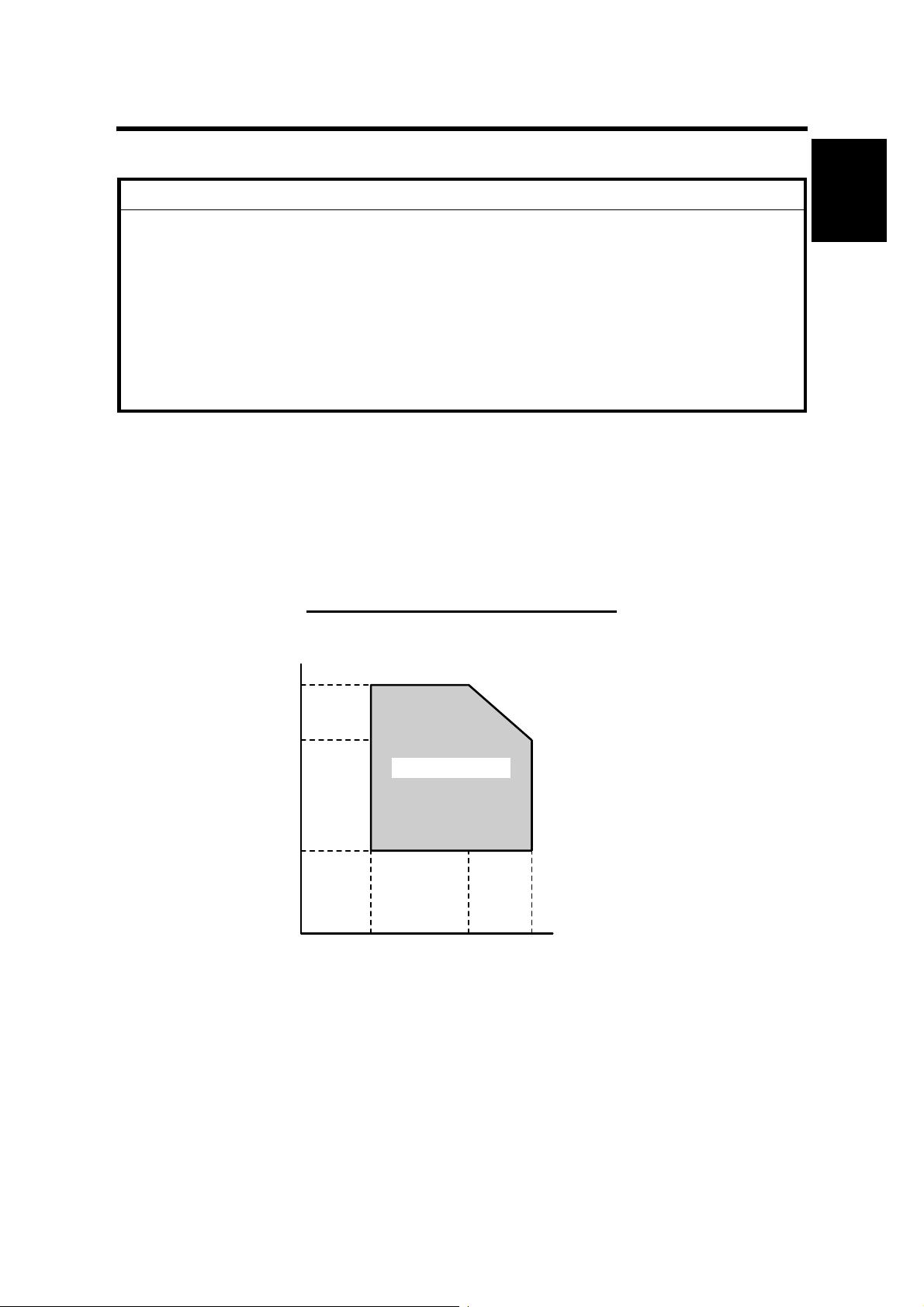
1.1.1 ENVIRONMENT
Installation
–Temperature and Humidity Chart–
Humidity
80%
54%
Operation range
15%
10°C
(50°F)
27°C
(80.6°F)
32°C
(89.6°F)
Temperature
B121I920.WMF
SM 1-1 B121/B122/B123

INSTALLATION REQUIREMENTS
1. Temperature Range:
10°C to 32°C (50°F to 89.6°F)
2. Humidity Range: 15% to 80% RH
3. Ambient
Less than 1,500 lux (do not expose to direct sunlight)
Illumination:
4. Ventilation: 3 times/hr/person or more
5. Ambient Dust: Less than 0.075 mg/m3 (2.0 x 10⁻⁶ oz/yd3)
6. Avoid areas exposed to sudden temperature changes:
1) Areas directly exposed to cool air from an air conditioner.
2) Areas directly exposed to heat from a heater.
7. Do not place the machine where it is exposed to corrosive gases.
8. Do not install the machine at any location over 2,000 m (6,500 ft.) above sea
level.
9. Place the copier on a strong and level base. (Inclination on any side should be
no more than 5 mm.)
10. Do not place the machine where it is subjected to strong vibrations.
1.1.2 MACHINE LEVEL
Front to back: Within 5 mm (0.2") of level
Right to left: Within 5 mm (0.2") of level
B121/B122/B123 1-2 SM
Loading...