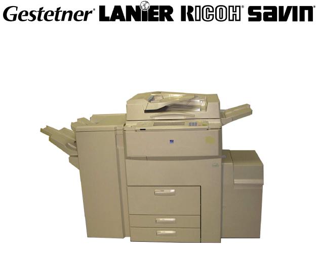
Ricoh A 551P, A 700, A 1055, A 700P, A 551 Service Manual
...
A292/A293/A292P/A293P
B098 SERVICE MANUAL
(To be used in conjunction with A229 Service Manual)
000930MIU
RICOH GROUP COMPANIES

®
®
|
|
MANUAL SERVICE |
A292/A293/A292P/A293P/B098 |
RICOH GROUP COMPANIES

A292/A293/A292P/A293P
B098
SERVICE MANUAL
000930MIU

It is the reader's responsibility when discussing the information contained within this document to maintain a level of confidentiality that is in the best interest of Ricoh Corporation and its member companies.
NO PART OF THIS DOCUMENT MAY BE REPRODUCED IN ANY
FASHION AND DISTRIBUTED WITHOUT THE PRIOR
PERMISSION OF RICOH CORPORATION.
All product names, domain names or product illustrations, including desktop images, used in this document are trademarks, registered trademarks or the property of their respective companies.
They are used throughout this book in an informational or editorial fashion only and for the benefit of such companies. No such use, or the use of any trade name, or web site is intended to convey endorsement or other affiliation with Ricoh products.
2002 RICOH Corporation. All rights reserved.

WARNING
The Service Manual contains information regarding service techniques, procedures, processes and spare parts of office equipment distributed by Ricoh Corporation. Users of this manual should be either service trained or certified by successfully completing a Ricoh Technical Training Program.
Untrained and uncertified users utilizing information contained in this service manual to repair or modify Ricoh equipment risk personal injury, damage to property or loss of warranty protection.
Ricoh Corporation
LEGEND
PRODUCT CODE |
|
|
|
|
|
GESTETNER |
LANIER |
RICOH |
SAVIN |
A292 |
3355 |
5455 |
Aficio 551 |
2055DP |
A293 |
3370 |
5470 |
Aficio 700 |
2070DP |
A292 |
-- |
|
Aficio 551P |
-- |
w/G594 Controller |
|
|||
|
|
|
|
|
A293 |
-- |
|
Aficio 700P |
-- |
w/G594 Controller |
|
|||
|
|
|
|
|
B098 |
5502 |
LD055 |
Aficio 1055 |
2555 |
DOCUMENTATION HISTORY
REV. NO. |
DATE |
COMMENTS |
* |
5/2000 |
Original Printing |
1 |
10/2002 |
B098 Addition |
|
|
|
|
|
|
|
Rev. 10/2002 |
TABLE OF CONTENTS |
|
COMPARISON BETWEEN A292/A293 AND A229 |
|
OVERALL INFORMATION |
|
1. OVERALL MACHINE INFORMATION........................................ |
1-1 |
1.1 SPECIFICATIONS..................................................................................... |
1-1 |
1.1.1 COPIER ENGINE ............................................................................. |
1-1 |
1.1.2 ADF .................................................................................................. |
1-5 |
1.2 MACHINE CONFIGURATION................................................................... |
1-6 |
1.3 MECHANICAL COMPONENT LAYOUT ................................................... |
1-7 |
1.3.1 COPIER ENGINE ............................................................................. |
1-7 |
1.3.2 ADF .................................................................................................. |
1-9 |
1.4 PAPER PATH.......................................................................................... |
1-10 |
1.5 COPY PROCESS.................................................................................... |
1-11 |
1.6 DRIVE LAYOUT ...................................................................................... |
1-13 |
1.6.1 COPIER ENGINE ........................................................................... |
1-13 |
1.6.2 ADF ................................................................................................ |
1-14 |
1.7 ELECTRICAL COMPONENT DESCRIPTION......................................... |
1-15 |
1.7.1 COPIER ENGINE ........................................................................... |
1-15 |
1.7.2 ADF ................................................................................................ |
1-21 |
DETAILED DESCRITPIONS |
|
2. DETAILED DESCRIPTIONS ....................................................... |
2-1 |
2.1 DOCUMENT FEEDER .............................................................................. |
2-1 |
2.1.1 PICK-UP ROLLER RELEASE .......................................................... |
2-1 |
2.1.2 BOTTOM PLATE LIFT...................................................................... |
2-2 |
2.1.3 PICK-UP AND SEPARATION .......................................................... |
2-3 |
2.1.4 ORIGINAL FEED.............................................................................. |
2-4 |
2.1.5 ORIGINAL SIZE DETECTION.......................................................... |
2-5 |
Original Length ..................................................................................... |
2-5 |
Original Width ....................................................................................... |
2-5 |
2.1.6 ORIGINAL TRANSPORT ................................................................. |
2-6 |
2.1.7 ORIGINAL SKEW CORRECTION.................................................... |
2-7 |
2.1.13 ORIGINAL INVERSION AND FEED-OUT ...................................... |
2-8 |
General Operation ................................................................................ |
2-8 |
Original Inversion.................................................................................. |
2-9 |
Original Exit (Single-Sided Original Mode).......................................... |
2-10 |
Original Exit (Double-Sided Original Mode) ........................................ |
2-11 |
2.1.9 JAM CONDITIONS......................................................................... |
2-12 |
Feed-in................................................................................................ |
2-12 |
Feed-out ............................................................................................. |
2-12 |
Inversion ............................................................................................. |
2-12 |
SM |
i |
A292/A293/B098 |
Rev. 10/2002 |
|
2.2 SCANNING.............................................................................................. |
2-13 |
2.2.1 OVERVIEW .................................................................................... |
2-13 |
2.2.2 SCANNER DRIVE .......................................................................... |
2-14 |
2.2.3 ORIGINAL SIZE DETECTION IN BOOK MODE ............................ |
2-15 |
2.3 IMAGE PROCESSING ............................................................................ |
2-16 |
2.3.1 OVERVIEW .................................................................................... |
2-16 |
2.3.2 SBU ................................................................................................ |
2-17 |
2.3.3 AUTO IMAGE DENSITY (ADS)...................................................... |
2-18 |
2.3.4 IPU (IMAGE PROCESSING UNIT)................................................. |
2-19 |
Overview............................................................................................. |
2-19 |
2.3.5 IMAGE PROCESSING STEPS AND RELATED SP MODES......... |
2-20 |
2.3.6 AUTO SHADING ............................................................................ |
2-25 |
Black Level Correction........................................................................ |
2-25 |
White Level Correction........................................................................ |
2-25 |
2.3.7 BACKGROUND ERASE................................................................. |
2-26 |
Background Erase .............................................................................. |
2-26 |
2.3.13 INDEPENDENT DOT ERASE ...................................................... |
2-27 |
2.3.9 FILTERING, MAIN SCAN MAGNIFICATION/REDUCTION ........... |
2-28 |
Overview............................................................................................. |
2-28 |
Filtering ............................................................................................... |
2-28 |
Main Scan Magnification/Reduction.................................................... |
2-29 |
Sub Scan Magnification ...................................................................... |
2-29 |
2.3.10 GAMMA (G) CORRECTION......................................................... |
2-30 |
2.3.11 GRADATION PROCESSING ....................................................... |
2-30 |
Three-graduation Processing.............................................................. |
2-30 |
Four-graduation Processing................................................................ |
2-31 |
Error Diffusion and Dithering............................................................... |
2-31 |
2.3.12 LINE WIDTH CORRECTION........................................................ |
2-31 |
2.4 LASER EXPOSURE................................................................................ |
2-32 |
2.4.1 AUTO POWER CONTROL............................................................. |
2-32 |
2.4.2 DUAL BEAM WRITING .................................................................. |
2-33 |
2.4.3 LASER BEAM PITCH CHANGE MECHANISM |
|
(FOR A292/A293 ONLY) ................................................................. |
2-34 |
2.4.4 LD SAFETY SWITCHES ................................................................ |
2-35 |
2.5 DRUM UNIT ............................................................................................ |
2-36 |
2.5.1 PROCESS CONTROL.................................................................... |
2-36 |
Overview............................................................................................. |
2-36 |
Drum potential sensor calibration ....................................................... |
2-37 |
VSG adjustment.................................................................................. |
2-37 |
VG Adjustment.................................................................................... |
2-38 |
LD power adjustment.......................................................................... |
2-39 |
Toner Density Adjustment................................................................... |
2-39 |
VREF Update...................................................................................... |
2-40 |
2.5.2 DRUM UNIT COMPONENTS......................................................... |
2-41 |
2.5.3 DRUM CHARGE............................................................................. |
2-42 |
Overview............................................................................................. |
2-42 |
Charge Corona Wire Cleaning Mechanism......................................... |
2-43 |
2.5.4 DRUM CLEANING AND TONER RECYCLING.............................. |
2-44 |
Overview............................................................................................. |
2-44 |
A292/A293/B098 |
ii |
SM |
Rev. 10/2002
Drive Mechanism ................................................................................ |
2-45 |
Cleaning Blade Pressure Mechanism and Side-to-Side Movement.... |
2-46 |
2.5.5 OTHERS......................................................................................... |
2-47 |
Air Flow Around the Drum................................................................... |
2-47 |
Pick-off Mechanism ............................................................................ |
2-48 |
2.6 DEVELOPMENT AND TONER SUPPLY ................................................ |
2-49 |
2.6.1 OVERVIEW .................................................................................... |
2-49 |
2.6.2 DEVELOPMENT MECHANISM...................................................... |
2-50 |
2.6.3 DEVELOPMENT BIAS ................................................................... |
2-51 |
2.6.4 TONER DENSITY CONTROL ........................................................ |
2-52 |
Overview............................................................................................. |
2-52 |
Sensor control mode........................................................................... |
2-52 |
Image pixel count control.................................................................... |
2-53 |
2.6.5 TONER END DETECTION............................................................. |
2-54 |
Toner Near End .................................................................................. |
2-54 |
Toner End ........................................................................................... |
2-54 |
2.6.6 TONER END RECOVERY ............................................................. |
2-54 |
2.6.7 ABNORMAL TD AND ID SENSOR CONDITIONS ......................... |
2-55 |
2.7 IMAGE TRANSFER AND PAPER SEPARATION................................... |
2-56 |
2.7.1 IMAGE TRANSFER AND PAPER SEPARATION MECHANISM ... |
2-56 |
2.7.2 TRANSFER BELT UNIT LIFT MECHANISM.................................. |
2-57 |
2.7.3 TRANSFER BELT CLEANING MECHANISM ................................ |
2-58 |
2.13 PAPER FEED........................................................................................ |
2-59 |
2.13.1 OVERVIEW .................................................................................. |
2-59 |
2.13.2 DRIVE MECHANISM.................................................................... |
2-60 |
2.13.3 TANDEM LCT – TRAY 1 .............................................................. |
2-61 |
Overview............................................................................................. |
2-61 |
Connecting the Left and Right Sides of the Tray ................................ |
2-62 |
Paper Lift/Remaining Paper Detection................................................ |
2-63 |
Fence Drive ........................................................................................ |
2-65 |
Rear Fence Drive................................................................................ |
2-66 |
Tray Positioning .................................................................................. |
2-67 |
2.13.4 TRAY POSITIONING MECHANISM – TRAYS 1 TO 3 ................. |
2-68 |
2.13.5 PAPER LIFT MECHANISM - TRAYS 2 AND 3............................. |
2-69 |
2.13.6 VERTICAL TRANSPORT MECHANISM ...................................... |
2-70 |
2.13.7 PAPER REGISTRATION.............................................................. |
2-71 |
Overview............................................................................................. |
2-71 |
2.13.13 PAPER SIZE DETECTION – TRAY 2 ........................................ |
2-72 |
2.9 IMAGE FUSING ...................................................................................... |
2-73 |
2.9.1 OVERVIEW .................................................................................... |
2-73 |
2.9.2 FUSING ENTRANCE GUIDE ......................................................... |
2-74 |
2.9.3 FUSING DRIVE MECHANISM ....................................................... |
2-75 |
2.10 PAPER EXIT/DUPLEX .......................................................................... |
2-76 |
2.10.1 OVERVIEW .................................................................................. |
2-76 |
2.10.2 INVERTER ................................................................................... |
2-77 |
Feed-in and Jogging ........................................................................... |
2-77 |
Feed-out ............................................................................................. |
2-78 |
2.10.3 DUPLEX TRAY FEED MECHANISM ........................................... |
2-79 |
2.10.4 BASIC DUPLEX FEED OPERATION........................................... |
2-80 |
SM |
iii |
A292/A293/B098 |
Rev. 10/2002 |
|
Longer than A4 / Letter lengthwise ..................................................... |
2-80 |
2.11 ENERGY SAVER MODES .................................................................... |
2-83 |
2.11.1 LOW POWER MODE ................................................................... |
2-83 |
Entering low power mode ................................................................... |
2-83 |
What happens in low power mode...................................................... |
2-83 |
Return to stand-by mode .................................................................... |
2-83 |
INSTALLATION |
|
3. INSTALLATION PROCEDURE................................................... |
3-1 |
3.1 INSTALLATION REQUIREMENTS ........................................................... |
3-1 |
3.1.1 ENVIRONMENT ............................................................................... |
3-1 |
3.1.2 MACHINE LEVEL............................................................................. |
3-1 |
3.1.3 MINIMUM SPACE REQUIREMENTS............................................... |
3-2 |
3.1.4 POWER REQUIREMENTS .............................................................. |
3-2 |
3.2 COPIER (A292/A293/B0913) .................................................................... |
3-3 |
3.2.1 ACCESSORY CHECK...................................................................... |
3-3 |
3.2.2 INSTALLATION PROCEDURE ........................................................ |
3-4 |
3.3 LCT (11/B5137)....................................................................................... |
3-14 |
3.3.1 ACCESSORY CHECK.................................................................... |
3-14 |
3.3.2 INSTALLATION PROCEDURE ...................................................... |
3-15 |
3.4 3,000-SHEET FINISHER (9/B5136) ........................................................ |
3-20 |
3.4.1 ACCESSORY CHECK.................................................................... |
3-20 |
3.4.2 INSTALLATION PROCEDURE ...................................................... |
3-21 |
3.5 PUNCH UNIT INSTALLATION (A1312) FOR 9/B5136 FINISHER.......... |
3-24 |
3.5.1 ACCESSORY CHECK.................................................................... |
3-24 |
3.5.2 PUNCH UNIT INSTALLATION ....................................................... |
3-25 |
3.6 FINISHER (B302) .................................................................................... |
3-28 |
3.6.1 INSTALLATION PROCEDURE ...................................................... |
3-28 |
3.7 PUNCH UNIT INSTALLATION (A1312) FOR B302 FINISHER............... |
3-31 |
3.7.1 ACCESSORY CHECK.................................................................... |
3-31 |
3.7.2 PUNCH UNIT INSTALLATION ....................................................... |
3-32 |
3.13 KEY COUNTER INSTALLATION .......................................................... |
3-35 |
3.9 COPY CONNECTOR KIT INSTALLATION (10)...................................... |
3-36 |
3.10 LG KIT (B375/B51313) .......................................................................... |
3-39 |
3.10.1 ACCESSORY CHECK.................................................................. |
3-39 |
3.10.2 INSTALLATION PROCEDURE .................................................... |
3-40 |
SERVICE TABLES |
|
4. SERVICE TABLES...................................................................... |
4-1 |
4.1 GENERAL CAUTIONS.............................................................................. |
4-1 |
4.1.1 DRUM............................................................................................... |
4-1 |
4.1.2 DRUM UNIT ..................................................................................... |
4-1 |
4.1.3 TRANSFER BELT UNIT ................................................................... |
4-2 |
4.1.4 SCANNER UNIT............................................................................... |
4-2 |
4.1.5 LASER UNIT .................................................................................... |
4-2 |
4.1.6 CHARGE CORONA.......................................................................... |
4-3 |
A292/A293/B098 |
iv |
SM |
Rev. 10/2002 |
|
4.1.7 DEVELOPMENT .............................................................................. |
4-3 |
4.1.13 CLEANING ..................................................................................... |
4-4 |
4.1.9 FUSING UNIT................................................................................... |
4-4 |
4.1.10 PAPER FEED................................................................................. |
4-4 |
4.1.11 USED TONER ................................................................................ |
4-4 |
4.2 SERVICE PROGRAM MODE.................................................................... |
4-5 |
4.2.1 SERVICE PROGRAM MODE OPERATION..................................... |
4-5 |
Service Program Access Procedure ..................................................... |
4-5 |
Accessing Copy Mode from within an SP Mode ................................... |
4-7 |
Selecting the Program Number............................................................. |
4-8 |
Inputting a Value or Setting for an SP Mode......................................... |
4-9 |
4.2.2 SERVICE PROGRAM MODE TABLES .......................................... |
4-10 |
4.2.3 TEST PATTERN PRINTING (SP2-902) ......................................... |
4-66 |
Test Pattern Table (SP2-902-2: Test Pattern Printing – IPU) ............. |
4-66 |
Test Pattern Table (SP2-902-3: Test Pattern Printing – Printing) ....... |
4-66 |
4.2.4 INPUT CHECK ............................................................................... |
4-67 |
Main Machine Input Check (SP5-1303) .............................................. |
4-67 |
ADF Input Check (SP6-007) ............................................................... |
4-71 |
4.2.5 OUTPUT CHECK ........................................................................... |
4-72 |
Main Machine Output Check (SP5-1304) ........................................... |
4-72 |
ADF Output Check (SP6-0013) .......................................................... |
4-73 |
4.2.6 SYSTEM PARAMETER AND DATA LISTS (SMC LISTS) ............. |
4-73 |
4.2.7 MEMORY ALL CLEAR (SP5-1301)................................................ |
4-74 |
4.2.13 SOFTWARE RESET .................................................................... |
4-75 |
4.2.9 SYSTEM SETTING AND COPY SETTING (UP MODE) RESET ... |
4-75 |
System Setting Reset ......................................................................... |
4-75 |
Copy Features Reset.......................................................................... |
4-75 |
4.3 PROGRAM AND DATA DOWNLOAD..................................................... |
4-76 |
4.3.1 OVERVIEW .................................................................................... |
4-76 |
4.3.2 DOWNLOAD THE BICU SOFTWARE FROM BICU TO FLASH |
|
MEMORY CARD ............................................................................. |
4-77 |
4.3.3 DOWNLOAD NVRAM DATA TO THE BICU .................................. |
4-78 |
4.3.4 DOWNLOAD NVRAM DATA FROM BICU TO FLASH MEMORY |
|
CARD ............................................................................................. |
4-79 |
4.3.5 DOWNLOAD STAMP DATA TO THE BICU ................................... |
4-80 |
4.4 USER PROGRAM MODE ....................................................................... |
4-81 |
4.4.1 HOW TO ENTER AND EXIT UP MODE......................................... |
4-81 |
4.4.2 UP MODE TABLE .......................................................................... |
4-81 |
System Setting Table.......................................................................... |
4-81 |
Copy Features Table .......................................................................... |
4-82 |
4.4.3 IMAGE QUALITY SETTING BY UP MODE.................................... |
4-86 |
Text Mode........................................................................................... |
4-86 |
Text/Photo Mode ................................................................................ |
4-90 |
Photo Mode ........................................................................................ |
4-91 |
Pale Mode........................................................................................... |
4-92 |
Generation Mode ................................................................................ |
4-92 |
4.5 TEST POINTS/DIP SWITCHES/LEDS.................................................... |
4-93 |
4.5.1 DIP SWITCHES.............................................................................. |
4-93 |
4.5.2 TEST POINTS ................................................................................ |
4-93 |
SM |
v |
A292/A293/B098 |
Rev. 10/2002 |
|
4.5.3 FUSES............................................................................................ |
4-94 |
4.5.4 VARIABLE RESISTORS ................................................................ |
4-95 |
4.5.5 LEDS .............................................................................................. |
4-95 |
4.6 SPECIAL TOOLS AND LUBRICANTS .................................................... |
4-95 |
4.6.1 SPECIAL TOOLS ........................................................................... |
4-95 |
4.6.2 LUBRICANTS................................................................................. |
4-95 |
4.7 FIRMWARE HISTORY ............................................................................. |
4-96 |
PREVENTIVE MAINTENANCE |
|
5. PREVENTIVE MAINTENANCE SCHEDULE .............................. |
5-1 |
5.1 PM TABLE................................................................................................. |
5-1 |
REPLACEMENT AND ADJUSTMENT |
|
6. REPLACEMENT AND ADJUSTMENT........................................ |
6-1 |
6.1 EXTERIOR ................................................................................................ |
6-1 |
6.1.1 FILTERS........................................................................................... |
6-1 |
Ozone Filter: Duct................................................................................. |
6-1 |
Filter Vacuum........................................................................................ |
6-1 |
6.2 DOCUMENT FEEDER .............................................................................. |
6-2 |
6.2.1 COVER REMOVAL .......................................................................... |
6-2 |
6.2.2 FEED UNIT REMOVAL AND SEPARATION ROLLER |
|
REPLACEMENT............................................................................... |
6-4 |
6.2.3 FEED BELT REPLACEMENT .......................................................... |
6-5 |
6.2.4 PICK-UP ROLLER REPLACEMENT................................................ |
6-6 |
6.2.5 SENSOR REPLACEMENT............................................................... |
6-7 |
Entrance and Registration Sensors ...................................................... |
6-7 |
Width Sensor ........................................................................................ |
6-8 |
Exit Sensor and Inverter Sensor ........................................................... |
6-9 |
6.2.6 TRANSPORT BELT REPLACEMENT............................................ |
6-10 |
6.3 SCANNER UNIT...................................................................................... |
6-11 |
6.3.1 EXPOSURE GLASS....................................................................... |
6-11 |
6.3.2 LENS BLOCK ................................................................................. |
6-12 |
6.3.3 ORIGINAL SIZE SENSORS ........................................................... |
6-13 |
6.3.4 EXPOSURE LAMP......................................................................... |
6-14 |
6.3.5 SCANNER MOTOR / MCU............................................................. |
6-15 |
Scanner Motor .................................................................................... |
6-15 |
MCU.................................................................................................... |
6-15 |
6.3.6 SCANNER WIRES ......................................................................... |
6-16 |
Rear Scanner Drive Wire .................................................................... |
6-19 |
Front Scanner Drive Wire ................................................................... |
6-20 |
Reinstallation ...................................................................................... |
6-21 |
6.4 LASER UNIT ........................................................................................... |
6-23 |
6.4.1 CAUTION DECAL LOCATIONS..................................................... |
6-23 |
6.4.2 LD UNIT REPLACEMENT.............................................................. |
6-24 |
6.4.3 LASER BEAM PITCH ADJUSTMENT ............................................ |
6-25 |
6.4.4 POLYGON MIRROR MOTOR REPLACEMENT ............................ |
6-29 |
A292/A293/B098 |
vi |
SM |
Rev. 10/2002 |
|
6.5 DRUM UNIT ............................................................................................ |
6-30 |
6.5.1 DRUM POTENTIAL SENSOR REPLACEMENT ............................ |
6-30 |
6.5.2 DRUM MOTOR REPLACEMENT................................................... |
6-31 |
6.5.3 TONER OUTPUT AND RECYCLING PUMP UNIT |
|
REPLACEMENT............................................................................. |
6-32 |
6.6 DEVELOPMENT AND TONER SUPPLY ................................................ |
6-34 |
6.6.1 DEVELOPMENT AND AIR DUST FILTER REPLACEMENT ......... |
6-34 |
6.6.2 DEVELOPER REPLACEMENT...................................................... |
6-35 |
6.6.3 TONER END SENSOR REPLACEMENT....................................... |
6-37 |
6.6.4 DEVELOPMENT MOTOR REPLACEMENT .................................. |
6-37 |
6.7 TRANSFER BELT UNIT.......................................................................... |
6-38 |
6.7.1 TRANSFER BELT UNIT REMOVAL/INSTALLATION .................... |
6-38 |
- Removal - ......................................................................................... |
6-38 |
- Installation - ...................................................................................... |
6-38 |
6.13 PAPER FEED........................................................................................ |
6-40 |
6.13.1 PAPER TRAY REMOVAL ............................................................ |
6-40 |
Tandem Tray Removal ....................................................................... |
6-40 |
Universal trays (Customer adjust/Technician adjust) Removal........... |
6-42 |
6.13.2 REAR FENCE RETURN SENSOR REPLACEMENT................... |
6-43 |
6.13.3 REAR FENCE HP SENSOR REPLACEMENT............................. |
6-44 |
6.13.4 BOTTOM PAPER SENSOR REPLACEMENT ............................. |
6-45 |
6.13.5 BOTTOM PLATE LIFT WIRE REPLACEMENT ........................... |
6-46 |
6.13.6 TANDEM LCT PAPER SIZE CHANGE ........................................ |
6-48 |
6.13.7 BY-PASS PAPER SIZE BOARD REPLACEMENT....................... |
6-51 |
6.13.13 PAPER FEED CLUTCH/RELAY CLUTCH REMOVAL............... |
6-53 |
6.13.9 BY-PASS FEED MOTOR/CLUTCH REMOVAL ........................... |
6-56 |
6.13.10 REGISTRATION MOTOR REMOVAL ........................................ |
6-57 |
6.13.11 PAPER TRAY UNIT REMOVAL ................................................. |
6-58 |
6.9 FUSING UNIT.......................................................................................... |
6-59 |
6.9.1 FUSING UNIT REMOVAL .............................................................. |
6-59 |
6.9.2 FUSING THERMISTOR/THERMOFUSE/THERMOSTAT |
|
REPLACEMENT............................................................................. |
6-60 |
Fusing Thermistor Replacement......................................................... |
6-60 |
Fusing Thermofuse Replacement (for A292/A293 only) ..................... |
6-60 |
Fusing Thermostat Replacement (for B0913 only) ............................. |
6-61 |
Fusing Thermostat Replacement (for B0913 only) ............................. |
6-61 |
6.9.3 FUSING LAMP REPLACEMENT ................................................... |
6-62 |
6.9.4 HOT ROLLER REPLACEMENT..................................................... |
6-63 |
6.9.5 OIL SUPPLY/CLEANING ROLLER REPLACEMENT .................... |
6-65 |
6.9.6 PRESSURE ROLLER CLEANING ROLLER REPLACEMENT ...... |
6-66 |
6.9.7 MAGNET POSITION ADJUSTMENT ............................................. |
6-67 |
6.9.13 HOT ROLLER STRIPPER PAWL REPLACEMENT..................... |
6-68 |
6.10 PAPER EXIT/DUPLEX UNIT................................................................. |
6-70 |
6.10.1 1ST AND 2ND EXIT SENSOR ..................................................... |
6-70 |
6.10.2 JOGGER MOTOR ........................................................................ |
6-71 |
6.10.3 DUPLEX ENTRANCE SENSOR .................................................. |
6-71 |
6.10.4 DUPLEX TRANSPORT/DUPLEX FEED CLUTCHES .................. |
6-72 |
6.10.5 DUPLEX TRANSPORT SENSOR 1 ............................................. |
6-72 |
6.10.6 DUPLEX TRANSPORT SENSORS 2 & 3 .................................... |
6-73 |
SM |
vii |
A292/A293/B098 |
Rev. 10/2002 |
|
|
|
6.10.7 INVERTER EXIT CLUTCH ........................................................... |
6-74 |
|
6.10.13 DUPLEX INVERTER SENSOR .................................................. |
6-74 |
6.11 BOARDS AND OTHER ITEMS ............................................................. |
6-75 |
|
|
6.11.1 BICU BOARD ............................................................................... |
6-75 |
|
6.11.2 I/O BOARD ................................................................................... |
6-76 |
|
6.11.3 PSU .............................................................................................. |
6-77 |
|
6.11.4 PAPER FEED CONTROL BOARD (PFC) .................................... |
6-77 |
6.12 COPY IMAGE ADJUSTMENTS: PRINTING/SCANNING ..................... |
6-78 |
|
|
6.12.1 PRINTING .................................................................................... |
6-78 |
|
Registration - Leading Edge ............................................................... |
6-78 |
|
Registration – Side-to-Side ................................................................. |
6-78 |
|
Tray 1.................................................................................................. |
6-79 |
|
Tray 2.................................................................................................. |
6-79 |
|
Tray 3.................................................................................................. |
6-80 |
|
By-pass Tray....................................................................................... |
6-80 |
TROUBLESHOOTING |
|
|
7. TROUBLESHOOTING ................................................................ |
7-1 |
|
7.1 |
SERVICE CALL CONDITIONS ................................................................. |
7-1 |
|
7.1.1 SUMMARY ....................................................................................... |
7-1 |
|
7.1.2 SC CODE DESCRIPTIONS ............................................................. |
7-2 |
7.2 |
ELECTRICAL COMPONENT DEFECTS ................................................ |
7-46 |
|
7.2.1 SENSORS ...................................................................................... |
7-46 |
|
7.2.2 SWITCHES..................................................................................... |
7-50 |
7.3 |
BLOWN FUSE CONDITIONS ................................................................. |
7-51 |
FIRMWARE HISTORY |
|
|
8. A292/A293 FIRMWARE MODIFICATION HISTORY .................. |
8-1 |
|
3,000-SHEET FINISHER (B312/B586) |
|
|
1. OVERALL MACHINE INFORMATION........................................ |
9-1 |
|
1.1 |
SPECIFICATIONS..................................................................................... |
9-1 |
1.2 |
ELECTRICAL COMPONENT LAYOUT..................................................... |
9-4 |
1.3 |
ELECTRICAL COMPONENT DESCRIPTION........................................... |
9-6 |
1.4 |
MECHANICAL COMPONENT LAYOUT ................................................... |
9-8 |
1.5 |
DRIVE LAYOUT ........................................................................................ |
9-9 |
2. DETAILED DESCRIPTIONS ..................................................... |
9-10 |
|
2.1 |
TRAY AND STAPLER JUNCTION GATE MECHANISM ........................ |
9-10 |
|
Upper tray mode ................................................................................. |
9-10 |
|
Sort/stack mode.................................................................................. |
9-10 |
|
Staple mode........................................................................................ |
9-10 |
2.2 |
PRE-STACK MECHANISM ..................................................................... |
9-11 |
2.3 |
JOGGER UNIT PAPER POSITIONING MECHANISM............................ |
9-12 |
A292/A293/B098 |
viii |
SM |
|
|
Rev. 10/2002 |
|
Vertical Paper Alignment .................................................................... |
9-12 |
|
Horizontal Paper Alignment ................................................................ |
9-12 |
2.4 |
STAPLER UNIT MOVEMENT MECHANISM .......................................... |
9-13 |
|
Side-to-side:........................................................................................ |
9-13 |
|
Rotation: ............................................................................................. |
9-13 |
2.5 |
STAPLER ................................................................................................ |
9-14 |
2.6 |
FEED-OUT MECHANISM ....................................................................... |
9-15 |
2.7 |
SHIFT TRAY UP/DOWN MECHANISM .................................................. |
9-16 |
2.13 SHIFT TRAY SIDE-TO-SIDE MECHANISM.......................................... |
9-17 |
|
2.9 |
PUNCH UNIT DRIVE MECHANISM........................................................ |
9-18 |
2.10 PUNCH WASTE COLLECTION MECHNISM........................................ |
9-19 |
|
2.11 JAM CONDITIONS................................................................................ |
9-20 |
|
3. SERVICE TABLES.................................................................... |
9-21 |
|
3.1 |
DIP SWITCHES....................................................................................... |
9-21 |
3.2 |
TEST POINTS ......................................................................................... |
9-21 |
3.3 |
FUSES .................................................................................................... |
9-21 |
4. REPLACEMENT AND ADJUSTMENT...................................... |
9-22 |
|
4.1 |
COVER REPLACEMENT........................................................................ |
9-22 |
|
Rear Cover ......................................................................................... |
9-22 |
|
Upper Left Cover ................................................................................ |
9-22 |
|
Upper Cover ....................................................................................... |
9-22 |
|
Front Door........................................................................................... |
9-22 |
|
Left Front Cover.................................................................................. |
9-22 |
|
Shift Tray ............................................................................................ |
9-23 |
|
Lower Left Cover ................................................................................ |
9-23 |
|
Right Cover......................................................................................... |
9-23 |
|
Front Shift Tray Cover......................................................................... |
9-23 |
|
Rear Shift Tray Cover ......................................................................... |
9-23 |
4.2 |
POSITIONING ROLLER REPLACEMENT.............................................. |
9-24 |
4.3 |
ALIGNMENT BRUSH ROLLER REPLACEMENT ................................... |
9-25 |
4.4 |
SENSOR REPLACEMNT........................................................................ |
9-26 |
|
4.4.1 STACK HEIGHT SENSOR 1 AND 2............................................... |
9-26 |
|
4.4.2 UPPER TRAY PAPER LIMIT AND EXIT SENSOR........................ |
9-27 |
|
Upper Tray Paper Limit Sensor .......................................................... |
9-27 |
|
Upper Tray Exit Sensor....................................................................... |
9-27 |
|
4.4.3 SHIFT TRAY EXIT SENSOR.......................................................... |
9-28 |
|
4.4.4 ENTRANCE AND STAPLER TRAY ENTRANCE SENSOR |
...........9-29 |
|
Entrance Sensor ................................................................................. |
9-29 |
|
Stapler Tray Entrance Sensor............................................................. |
9-29 |
|
4.4.5 STAPLER ROTATION HP SENSOR.............................................. |
9-30 |
4.5 |
STAPLER REMOVAL.............................................................................. |
9-31 |
4.6 |
PUNCH POSITION ADJUSTMENT......................................................... |
9-32 |
|
Right to left.......................................................................................... |
9-32 |
|
Front to rear ........................................................................................ |
9-32 |
SM |
ix |
A292/A293/B098 |

Rev. 10/2002
BOOKLET FINISHER A763
1. OVERALL MACHINE INFORMATION...................................... |
10-1 |
|
1.1 |
SPECIFICATIONS................................................................................... |
10-1 |
1.2 |
ELECTRICAL COMPONENT DESCRIPTION......................................... |
10-3 |
1.3 |
MECHANICAL COMPONENT LAYOUT ................................................. |
10-7 |
2. DETAILED DESCRIPTIONS ..................................................... |
10-8 |
||
2.1 |
|
JUNCTION GATE MECHANISM............................................................. |
10-8 |
|
2.1.1 SHIFT TRAY MODE ....................................................................... |
10-8 |
|
|
|
A4/LT sideways or shorter .................................................................. |
10-8 |
|
|
Longer than A4 sideways.................................................................... |
10-8 |
|
2.1.2 PROOF TRAY MODE..................................................................... |
10-9 |
|
|
2.1.3 BOOKLET STITCH MODE ............................................................. |
10-9 |
|
2.2 |
|
PRE-STACK MECHANISM ................................................................... |
10-10 |
2.3 |
|
PAPER SHIFT MECHANISM ................................................................ |
10-11 |
2.4 |
|
PAPER POSITIONING MECHANISM ................................................... |
10-12 |
2.5 |
|
STAPLER UNIT MOVEMENT MECHANISM ........................................ |
10-13 |
|
2.5.1 DRIVE........................................................................................... |
10-13 |
|
|
2.5.2 MOVEMENT................................................................................. |
10-13 |
|
|
|
Front and Rear Stapling.................................................................... |
10-13 |
|
|
Tow-position Stapling........................................................................ |
10-13 |
2.6 |
|
STAPLER .............................................................................................. |
10-14 |
2.7 |
|
SHIFT TRAY MECHANISM................................................................... |
10-15 |
2.13 |
BOOKLET UNIT GATE MECHANISM................................................. |
10-16 |
|
2.9 |
|
RELAY ROLLER AND POSITIONING PLATE MECHANISM ............... |
10-18 |
2.10 |
POSITIONING ROLLER MECHANISM............................................... |
10-19 |
|
2.11 |
BOOKLET UNIT JOGGER MOVEMENT MECHANISM...................... |
10-20 |
|
2.12 |
BOOKLET STAPLER UNIT................................................................. |
10-21 |
|
2.13 |
PAPER FOLDER MECHANISM .......................................................... |
10-22 |
|
3. INSTALLATION ...................................................................... |
10-24 |
3.1 ACCESSORY CHECK .......................................................................... |
10-24 |
3.2 INSTALLATION PROCEDURE ............................................................. |
10-25 |
4. REPLACEMENT AND ADJUSTMENT.................................... |
10-30 |
4.1 REMOVAL............................................................................................. |
10-30 |
4.1.1 UPPER DOOR ............................................................................. |
10-30 |
4.1.2 UPPER REAR COVER................................................................. |
10-31 |
4.1.3 LOWER REAR COVER................................................................ |
10-31 |
4.1.4 TOP COVER ................................................................................ |
10-32 |
4.1.5 UPPER INNER COVER ............................................................... |
10-32 |
4.1.6 SHIFT TRAY UNIT ....................................................................... |
10-33 |
4.1.7 UPPER SHIFT GUIDE.................................................................. |
10-34 |
4.1.13 LOWER SHIFT GUIDE............................................................... |
10-34 |
4.1.9 EXIT UNIT .................................................................................... |
10-35 |
4.1.10 BUFFER ROLLER UNIT............................................................. |
10-36 |
4.1.11 STAPLER ................................................................................... |
10-37 |
A292/A293/B098 |
x |
SM |
|
|
Rev. 10/2002 |
|
4.1.12 FINISHER BOARD .................................................................... |
10-38 |
|
4.1.13 BOOKLET UNIT ......................................................................... |
10-39 |
|
4.1.14 FOLDER ROLLERS ................................................................... |
10-41 |
|
4.1.15 FOLDER PLATE......................................................................... |
10-44 |
|
Removal............................................................................................ |
10-44 |
|
Reinstalling ....................................................................................... |
10-45 |
|
4.1.16 BOOKLET STAPLER UNIT ........................................................ |
10-46 |
|
Removal............................................................................................ |
10-46 |
|
Adjustment........................................................................................ |
10-47 |
|
4.1.17 BOOKLET BOARD..................................................................... |
10-49 |
|
4.1.113 POSITIONING PLATE UNIT .................................................... |
10-49 |
|
4.1.19 1ST AND 2ND BOOKLET UNIT GATES .................................... |
10-50 |
4.2 |
ADJUSTMENT ...................................................................................... |
10-51 |
|
4.2.1 SHIFT TRAY HEIGHT .................................................................. |
10-51 |
|
4.2.2 JOGGER FENCE POSITION ....................................................... |
10-52 |
|
4.2.3 STAPLING POSITOIN.................................................................. |
10-53 |
|
4.2.4 BOOKLET STAPLING POSITION................................................. |
10-54 |
COPIER CONNECTION KIT B322 |
|
|
1. SPECIFICATIONS..................................................................... |
11-1 |
|
2. DETAILED DESCRIPTIONS ..................................................... |
11-2 |
|
2.1 |
OVERVIEW ............................................................................................. |
11-2 |
2.2 |
BASIC OPERATION................................................................................ |
11-3 |
|
2.2.1 NO SORT AND NO STAPLE MODE .............................................. |
11-3 |
|
2.2.2 SORT, STAPLE MODE .................................................................. |
11-4 |
|
2.2.3 OPERATION IN IRREGULAR CONDITIONS................................. |
11-5 |
|
Paper end during copying ................................................................... |
11-5 |
|
Copy tray full....................................................................................... |
11-5 |
|
Paper jam ........................................................................................... |
11-5 |
LCT A698/B587 |
|
|
1. OVERALL MACHINE INFORMATION...................................... |
12-1 |
|
1.1 |
SPECIFICATIONS................................................................................... |
12-1 |
1.2 |
MECHANICAL COMPONENT LAYOUT ................................................. |
12-2 |
1.3 |
ELECTRICAL COMPONENT LAYOUT................................................... |
12-3 |
1.4 |
ELECTRICAL COMPONENT DESCRIPTIONS ...................................... |
12-4 |
1.5 |
DRIVE LAYOUT ...................................................................................... |
12-5 |
2. DETAILED DESCRIPTIONS ..................................................... |
12-6 |
|
2.1 |
PAPER FEED MECHANISM................................................................... |
12-6 |
2.2 |
TRAY LIFT MECHANISM........................................................................ |
12-7 |
|
Tray lifting conditions .......................................................................... |
12-7 |
|
Tray lowering conditions ..................................................................... |
12-7 |
2.3 |
PAPER STACK HEIGHT DETECTION ................................................... |
12-9 |
SM |
xi |
A292/A293/B098 |
Rev. 10/2002
3. SERVICE TABLES.................................................................. |
12-10 |
|
3.1 |
TEST POINTS ....................................................................................... |
12-10 |
4. REPLACEMENT AND ADJUSTMENT.................................... |
12-11 |
|
4.1 |
COVER REMOVAL ............................................................................... |
12-11 |
|
Tray Cover ........................................................................................ |
12-11 |
|
Right Cover...................................................................................... |
12-11 |
|
Front Cover....................................................................................... |
12-11 |
|
Upper Rear Cover............................................................................. |
12-11 |
|
Lower Rear Cover............................................................................. |
12-12 |
|
Feed Unit Cover................................................................................ |
12-12 |
4.2 |
ROLLER REPLACEMENT .................................................................... |
12-13 |
|
4.2.1 PAPER FEED, SEPARATION, AND PICK-UP ROLLERS ........... |
12-13 |
|
Pick-up Roller ................................................................................... |
12-13 |
|
Paper Feed Roller............................................................................. |
12-13 |
|
Separation Roller .............................................................................. |
12-13 |
4.3 |
PAPER END SENSOR REPLACEMENT.............................................. |
12-14 |
4.4 |
PAPER FEED SENSOR REPLACEMENT............................................ |
12-15 |
4.5 |
PAPER POSITION SENSOR REPLACEMENT .................................... |
12-16 |
4.6 |
PICK-UP SOLENOID REPLACEMENT................................................. |
12-17 |
4.7 |
LIFT MOTOR REPLACEMENT ............................................................. |
12-18 |
4.13 SIDE FENCE POSITION CHANGE..................................................... |
12-19 |
|
3,000-SHEET FINISHER B302 |
|
|
1. OVERALL MACHINE INFORMATION...................................... |
13-1 |
|
1.1 |
SPECIFICATIONS................................................................................... |
13-1 |
1.2 |
MECHANICAL COMPONENT LAYOUT ................................................. |
13-3 |
1.3 |
ELECTRICAL COMPONENT DESCRIPTION......................................... |
13-4 |
1.4 |
DRIVE LAYOUT ...................................................................................... |
13-6 |
2. DETAILED DESCRIPTIONS ..................................................... |
13-7 |
|
2.1 |
TRAY AND STAPLER JUNCTION GATE ............................................... |
13-7 |
|
Upper Tray Mode................................................................................ |
13-7 |
|
Sort/Stack Mode ................................................................................. |
13-7 |
|
Staple Mode........................................................................................ |
13-7 |
2.2 |
PAPER PRE-STACKING ........................................................................ |
13-8 |
2.3 |
JOGGER UNIT PAPER POSITIONING .................................................. |
13-9 |
|
Vertical Paper Alignment .................................................................... |
13-9 |
|
Horizontal Paper Alignment ................................................................ |
13-9 |
|
Paper Stack Correction....................................................................... |
13-9 |
2.4 |
STAPLER UNIT MOVEMENT ............................................................... |
13-10 |
|
Side-to-Side ...................................................................................... |
13-10 |
|
Rotation (1) ....................................................................................... |
13-11 |
|
Rotation (2) ....................................................................................... |
13-11 |
2.5 |
STAPLER .............................................................................................. |
13-12 |
2.6 |
FEED-OUT ............................................................................................ |
13-14 |
2.7 |
SHIFT TRAY UP/DOWN MOVEMENT.................................................. |
13-15 |
A292/A293/B098 |
xii |
SM |
|
Rev. 10/2002 |
|
2.13 SHIFT TRAY SIDE-TO-SIDE MOVEMENT......................................... |
13-16 |
|
2.9 |
PUNCH UNIT DRIVE ............................................................................ |
13-17 |
2.10 PUNCH WASTE COLLECTION .......................................................... |
13-18 |
|
2.11 JAM CONDITIONS.............................................................................. |
13-19 |
|
3. SERVICE TABLES.................................................................. |
13-20 |
|
3.1 |
DIP SWITCHES..................................................................................... |
13-20 |
3.2 |
TEST POINTS ....................................................................................... |
13-20 |
3.3 |
FUSES .................................................................................................. |
13-20 |
4. REPLACEMENT AND ADJUSTMENT.................................... |
13-21 |
|
4.1 |
COVER REPLACEMENT...................................................................... |
13-21 |
|
Front Door......................................................................................... |
13-21 |
|
Left Inner Cover ................................................................................ |
13-21 |
|
Inner Cover ....................................................................................... |
13-21 |
|
Table................................................................................................. |
13-22 |
|
Upper Tray........................................................................................ |
13-22 |
|
Left Upper Cover .............................................................................. |
13-22 |
|
Left Lower Cover............................................................................... |
13-22 |
|
Upper Cover ..................................................................................... |
13-22 |
|
Rear Cover ....................................................................................... |
13-22 |
|
Shift Tray .......................................................................................... |
13-23 |
|
Front Shift Tray Cover....................................................................... |
13-23 |
|
Rear Shift Tray Cover ....................................................................... |
13-23 |
4.2 |
POSITIONING ROLLER REPLACEMENT............................................ |
13-24 |
4.3 |
ALIGNMENT BRUSH ROLLER REPLACEMENT ................................. |
13-25 |
4.4 |
SENSOR REPLACEMENT ................................................................... |
13-26 |
|
4.4.1 STACK HEIGHT 1, 2 AND EXIT GUIDE OPEN SENSOR ........... |
13-26 |
|
Stack Height Sensors 1 and 2 .......................................................... |
13-26 |
|
Exit Guide Open Sensor ................................................................... |
13-26 |
|
4.4.2 UPPER TRAY PAPER LIMIT AND EXIT SENSOR...................... |
13-27 |
|
Upper Tray Paper Limit Sensor ........................................................ |
13-27 |
|
Upper Tray Exit Sensor..................................................................... |
13-27 |
|
4.4.3 SHIFT TRAY EXIT SENSOR........................................................ |
13-28 |
|
4.4.4 ENTRANCE AND STAPLER TRAY ENTRANCE SENSORS ...... |
13-29 |
|
Entrance Sensor ............................................................................... |
13-29 |
|
Stapler Tray Entrance Sensor........................................................... |
13-29 |
|
4.4.5 PRE-STACK STOPPER SENSOR............................................... |
13-30 |
|
4.4.6 STAPLE WASTE HOPPER SENSOR.......................................... |
13-31 |
|
4.4.7 STAPLER ROTATION HP AND STAPLER RETURN SENSORS13-32 |
|
|
Stapler Rotation HP Sensor.............................................................. |
13-32 |
|
Stapler Return Sensor ...................................................................... |
13-32 |
4.5 |
STAPLER REMOVAL............................................................................ |
13-33 |
4.6 |
PUNCH POSITION ADJUSTMENT....................................................... |
13-34 |
|
Right to Left ...................................................................................... |
13-34 |
|
Front to Rear..................................................................................... |
13-34 |
SM |
xiii |
A292/A293/B098 |

!IMPORTANT SAFETY NOTICES
PREVENTION OF PHYSICAL INJURY
1.Before disassembling or assembling parts of the copier and peripherals, make sure that the copier power cord is unplugged.
2.The wall outlet should be near the copier and easily accessible.
3.Note that some components of the copier and the paper tray unit are supplied with electrical voltage even if the main power switch is turned off.
4.If any adjustment or operation check has to be made with exterior covers off or open while the main switch is turned on, keep hands away from electrified or mechanically driven components.
5.If the Start key is pressed before the copier completes the warm-up period (the Start key starts blinking red and green alternatively), keep hands away from the mechanical and the electrical components as the copier starts making copies as soon as the warm-up period is completed.
6.The inside and the metal parts of the fusing unit become extremely hot while the copier is operating. Be careful to avoid touching those components with your bare hands.
HEALTH SAFETY CONDITIONS
1.Never operate the copier without the ozone filters installed.
2.Always replace the ozone filters with the specified ones at the specified intervals.
3.Toner and developer are non-toxic, but if you get either of them in your eyes by accident, it may cause temporary eye discomfort. Try to remove with eye drops or flush with water as first aid. If unsuccessful, get medical attention.
OBSERVANCE OF ELECTRICAL SAFETY STANDARDS
1.The copier and its peripherals must be installed and maintained by a customer service representative who has completed the training course on those models.
2.The NVRAM on the system control board has a lithium battery which can explode if replaced incorrectly. Replace the NVRAM only with an identical one. The manufacturer recommends replacing the entire NVRAM. Do not recharge or burn this battery. Used NVRAM must be handled in accordance with local regulations.
1

1.SAFETY AND ECOLOGICAL NOTES FOR DISPOSAL
Do not incinerate toner bottles or used toner. Toner dust may ignite suddenly when exposed to an open flame.
2.Dispose of used toner, developer, and organic photoconductors in accordance with local regulations. (These are non-toxic supplies.)
3.Dispose of replaced parts in accordance with local regulations.
4.When keeping used lithium batteries in order to dispose of them later, do not put more than 100 batteries per sealed box. Storing larger numbers or not sealing them apart may lead to chemical reactions and heat build-up.
LASER SAFETY
The Center for Devices and Radiological Health (CDRH) prohibits the repair of laser-based optical units in the field. The optical housing unit can only be repaired in a factory or at a location with the requisite equipment. The laser subsystem is replaceable in the field by a qualified Customer Engineer. The laser chassis is not repairable in the field. Customer engineers are therefore directed to return all chassis and laser subsystems to the factory or service depot when replacement of the optical subsystem is required.
!WARNING
Use of controls, or adjustment, or performance of procedures other than those specified in this manual may result in hazardous radiation exposure.
!WARNING
WARNING: Turn off the main switch before attempting any of the procedures in the Laser Unit section. Laser beams can seriously damage your eyes.
CAUTION MARKING:
2

Rev. 10/2002
OVERALL INFORMATION A292/A293/B098
3,000 SHEET FINISHER B312/B586
DETAILED DESCRIPTIONS A292/A293/B098
BOOKLET FINISHER A763
INSTALLATION A292/A293/B098
COPIER CONNECTION KIT B322
SERVICE TABLES A292/A293/B098
LCT A698/B587
PREVENTIVE MAINTENANCE A292/A293/B098
3,000 SHEET FINISHER B302
REPLACEMENT AND ADJUSTMENT A292/A293/B098
TROUBLESHOOTING A292/A293/B098
FIRMWARE HISTORY A292/A293/B098
TAB |
POSITION 1 |
|
|
|
|
TAB |
POSITION 2 |
|
|
|
|
TAB |
POSITION 3 |
|
|
|
|
TAB |
POSITION 4 |
|
|
|
|
TAB |
POSITION 5 |
|
|
|
|
TAB |
POSITION 6 |
|
|
|
|
TAB |
POSITION 7 |
|
|
|
|
TAB |
POSITION 8 |
|
|
 Loading...