


 Loading...
Installation Instructions | Installationsanleitung | Notice d’installation Istruzioni per l’installazione | Instrucciones de instalación
Sartorius
YDO01M-232 (A11)
YDO01M-232CLK (A31)
YDO01M-232CO (A1)
YDO01M-485 (A2 | A3)
YDA01M-20MA (A9)
YDO01M-IO (A5)
YDO01M-EN (B9)
Data Output Port for Midrics® COM1 and UniCOM Interfaces Datenausgang für Midrics®-Schnittstellen COM1 und UniCOM Port de sortie pour interfaces Midrics® COM1 et UniCOM Porta in uscita per interfacce Midrics® COM1 e UniCOM Puerto de salida para interfaces COM1 y UniCOM de Midrics®
98647-004-16

English – page 3
In cases involving questions of interpretation, the German-language version shall prevail.
Deutsch – Seite 20
Im Auslegungsfall ist die deutsche Sprache maßgeblich.
Français – page 37
En cas de questions concernant l’interprétation, la version en langue allemande fera autorité.
Italiano – pagina 54
In caso di interpretazione dubbia, fa testo la versione in lingua tedesca.
Español – página 71
En caso de interpretación, la versión en lengua alemana será determinante.
2

Intended Use |
Contents |
|
The YD.01M-... data output port is |
|
Symbols |
3 |
Intended Use |
|
designed for installation in Midrics® |
|
The following symbols are used in |
|
Installation in the Display and |
|
model MIS... and MW... display and |
|
these instructions: |
4 |
|
|
control units and complete scales as an |
§ |
|
|
Control Unit |
|
optional standard COM1 interface or |
indicates required steps |
4 |
Installing the COM1 PCB |
|
|
UniCOM universal data interface. |
$ |
indicates steps required only under |
5 |
Installing the UniCOM PCB |
|
For COM1: |
7 |
Installing the Interface Cable |
||
|
|
certain conditions |
|
Configuring the Interface Module: |
|
– |
YDO01M-232 (Option A11): |
|
|
8 |
|
|
Bidirectional RS-232 data interface. |
> |
describes what happens after you |
|
YDO01M-485, YDA01M-20MA |
|
You can connect the following to the |
|
have performed a particular step |
|
YDO01M-IO: Specifications |
|
YDO01M-232 port: Printer (YDP02IS, |
! indicates a hazard |
10 |
||
|
YDP03, YDP04IS, YDP12IS, universal |
10 |
YDO01M-EN |
||
|
printer) or computer (SBI, XBPI or SMA |
|
|
|
Pin Assignment Charts |
|
operation). |
|
|
11 |
|
|
– Alibi memory |
|
|
11 |
COM1 |
|
– YBT01 external Bluetooth adapter |
|
|
11 |
UniCOM |
|
– YRD02Z second display |
|
|
|
Configuring COM1 and UniCOM |
|
– USB adapter cable, for connecting |
|
|
12 |
|
|
a computer over USB (part no. |
|
|
|
Synchronization |
|
YCC01IS). |
|
|
16 |
|
– YDO01M-232CLK “Clock" (Option A31): |
|
|
17 |
Data Interfaces |
|
|
As standard RS-232, plus date/time |
|
|
17 |
Data Input Format (Commands) |
|
For UniCOM: |
|
|
18 |
Data Output Format |
|
|
|
19 |
GMP-compliant Printouts |
|
– |
YDO01M-232CO (Option A1): |
|
|
|
|
|
as for RS-232, plus digital I/O (TTL/5V) |
|
|
|
|
– YDO01M-485 (Options A2 and A3): |
|
|
|
|
|
|
Bidirectional data interface, electrically |
|
|
|
|
|
isolated, for use with the RS-422 |
|
|
|
|
|
(Option A2) or RS-485 (Option A3) pro- |
|
|
|
|
|
tocol. |
|
|
|
|
|
The YDO01M-485 lets you network up |
|
|
|
|
|
to 32 Midrics scales/display and control |
|
|
|
|
|
units in an XBPI-bus. |
|
|
|
|
– |
YDA01M-20MA (Option A9): |
|
|
|
|
|
Analog output port for use as a current |
|
|
|
|
|
interface (0/4 to 20 mA, 0 - 24 mA) or |
|
|
|
|
|
voltage interface (0 to 24 volts). |
|
|
|
|
|
The YDA01-20MA module enables con- |
|
|
|
|
|
nection of a PLC system or a remote |
|
|
|
|
|
analog display unit. |
|
|
|
|
– |
YDO01M-IO (Option A5): |
|
|
|
|
|
Digital input/output module; for con- |
|
|
|
|
|
necting Midrics equipment to external |
|
|
|
|
|
controllers. |
|
|
|
|
– |
YDO01M-EN (Option B9): |
|
|
|
|
|
Ethernet interface (e.g. for connecting |
|
|
|
|
|
to a PLC or PC). |
|
|
|
|
3
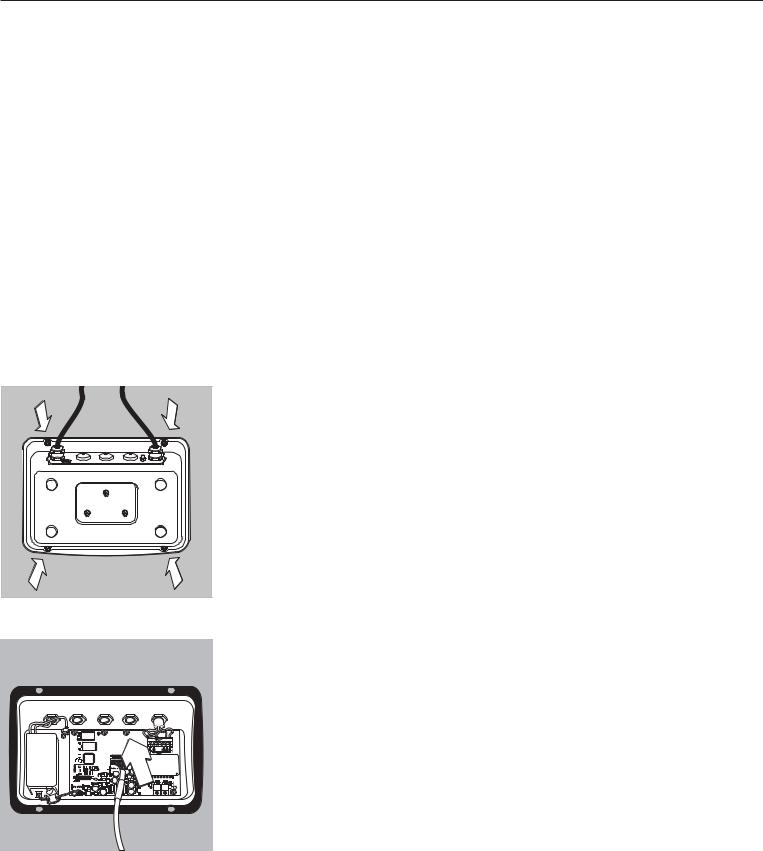
Installation in the Display and Control Unit
Installation
Installation of the interface module in the Midrics display and control unit (and additionally the installation of the cable gland and connection of the connecting cable to the terminal screw strip) is only required if the Midrics display and control unit was not equipped at the factory with this data output in accordance with the customer's order.
Notes:
§The interface module should be installed by a certified technician who has received specialized training from Sartorius.
§IP65 protection:
Make sure to use the connecting cable with screw-lock hardware designed for the interface module in question (see “Accessories").
!Make sure to disconnect the equipment from power before beginning installation.
!Any installation work that does not conform to the instructions in this manual will result in forfeiture of all claims under the manufacturer's warranty.
!Installation work that affects the IP65 protection rating must be performed with extreme care.
The cable gland (IP65 protection) for connection of the interface to the display and control unit is covered by a protective cap. Please use extreme caution when performing any work on the equipment that affects this cable gland.
§ To open the display and control unit, remove the screws from the front panel.
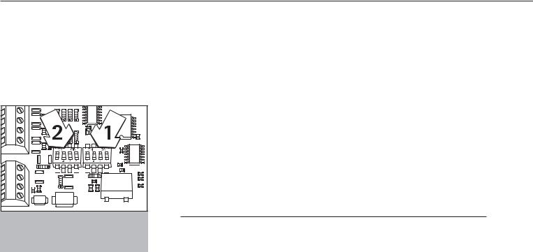
Installing the COM1 PCB:
§ Remove fastening screw.
4
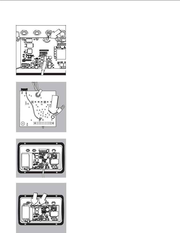
§ Attach spacing bolts.
§ Plug in PCB mounting.
§Plug the interface module (YDO01M-232 or YDO01M-232CLK) onto the digital PCB in the Midrics display and control unit. To do this, attach the female terminal strips on the interface module to the corresponding male terminal strips on the digital PCB.
§Fasten the interface module with the screw.
The interface modules are equipped with their own terminal screw strips. Connect the cable to this terminal strip.
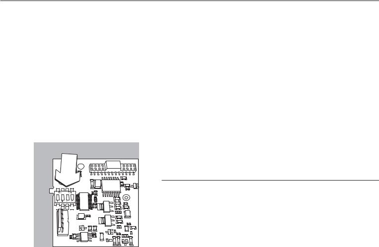
Installing the UniCOM PCB:
§Remove the 2 fastening screws.
5
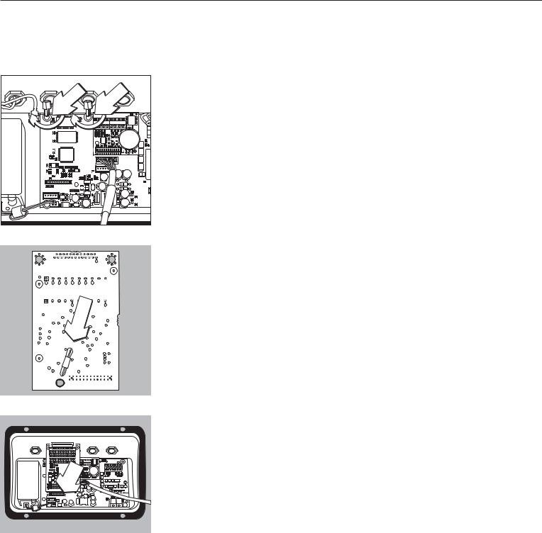
§ Attach the 2 spacing bolts.
§ Plug in PCB mounting.
§Plug the interface module (YDO01M-232CO, YDO01M-485, YDA01M-20MA or YDO01M-IO) onto the digital PCB in the Midrics display and control unit. To do this, attach the female terminal strips on the interface module to the corresponding male terminal strips on the digital PCB.
§Fasten the interface module with the 2 screws.
The interface modules are equipped with their own terminal screw strips. Connect the cable to this terminal strip.
6
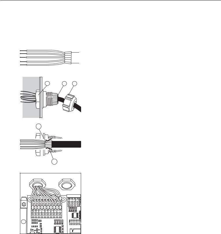
Installing the Interface Cable
§Pin assignments: please see “Pin Assignment Charts" in this manual.
§Use the cable gland to connect the peripheral device to the indicator.
§ Prepare the cable as follows:
– Expose approximately 10 cm (4 in) of the cable end for installation
– Remove all but approximately 1 cm (1/2 inch) of the shielding and fold it back over the casing
–Strip the casing from approximately 1 mm (1/2 inch) of the wires and attach ferrules to the wire ends.
1 |
5 |
4 |
§ Attach the cable gland: |
!Please use extreme caution when performing any work on the equipment that affects this cable gland. Use a torque wrench and tighten the cable gland to 5 Nm.
– Remove the protective cap from the bore hole on the display and control unit.
– Guide the enclosed cable gland through the bore hole and secure it inside the housing with the nut (1).
2
– Slide the cable gland over the cable until the clamps (3) are in contact with the shield (2). Tighten the nut (4) until the sealing clamp (5) forms a slight ridge between nut and cable.
– Make sure the shield is in contact with the clamps.
3 |
§ |
– |
– |
Connect the cable:
Connect the wires securely in accordance with the terminal assignments. Please see “Pin Assignment Charts" in this manual for details.
§Close the display and control unit. Make sure that the rubber seal between the front panel and the housing is correctly positioned.
§After you close the housing again, use a pressure gauge to check the integrity of the IP65 protection. For details, contact the Sartorius Service Center.
Setting the Operating Parameters in the COM1 and UniCOM Interfaces
After installing and configuring the interface module in the display and control unit, select the parameters in the operating menu that correspond to your requirements. For details, see “Configuring COM1 and UniCOM." For more information, refer to the installation and operating instructions for the Midrics scale.
7
Configuring the Interface Module:
YDO01M-485, YDA01M-20MA
YDO01M-485 (Options A2 and A3)
Characteristics
The YDO01M-485 module (serial RS-485/RS-422 interface, electrically isolated1) can be operated with your choice of RS-485 or RS-422 protocol.
The module is configured by eight switches.
In addition to defining whether RS-485 or RS-422 is used, certain terminating resistors (120 O) and/or bias resistors may have to be activated or deactivated, depending on whether a network or point-to-point connection is used.
The positions of the switches are indicated in the drawing on the left. Close switches 1 through 4 for RS-422 operation.
The following list shows the functions of switches in the closed (“ON") position:
Function (on = closed) |
Switch |
Terminating resistor, transmitting side 120O |
1 - 1 |
Bias resistor, transmitting side (TxD+, pull-up) 680O |
1 - 2 |
Bias resistor, transmitting side (TxD–, pull-down) 680O |
1 - 3 |
ON: RS-422 operation | open: RS-485 mode |
1 - 4 |
Terminating resistor, receiving side 120O |
2 - 1 |
Bias resistor, receiving side (RxD+, pull-up) 680O |
2 - 2 |
Bias resistor, receiving side (RxD–, pull-down) 680O |
2 - 3 |
No function |
2 - 4 |
Note on setting the switches:
Switches must be set pairwise as follows:
–Switches 1–2 and 1–3: both ON or both OFF
–Switches 2–2 and 2–3: both ON or both OFF
Operation as an RS-485 Interface (Option A3):
§Switches 1 - 4 must be open to operate the module in RS-485 mode (factory setting).
§If necessary, deactivate the bias resistors for the RS-485 mode. To do this, open the switch (factory setting).
The bias resistors must occur no more than once per data transmission path (whether over a network or in a point-to-point connection); otherwise, transmission errors may occur. Please refer to the specifications or wiring diagram for the remote station or network node in question for detailed information. Always activate or deactivate bias resistors in pairs.
§The terminating resistor (transmitting side, switch 1 – 1) must be activated if the device is at either end of an RS-1 bus system, or when connected point-to-point with another device. The remote station must also have a 120-O terminating resistor. If necessary, activate the terminating resistor (120 O) for RS-485 operation:
close switches 1 - 1 and 2 - 1 (“ON")
Operation as an RS-422 Interface (Option A2):
§Close switches 1 - 4 for RS-422 operation (“ON")
§If necessary, deactivate the bias resistors for RS-422-operation. To do this, open the switches.
§Activate the terminating resistor on the receiving side (switch 2 – 1), if no external terminating resistor is available. Always deactivate terminating resistors on the transmitting side (switch 1 – 1).
1) The shielding in the connecting cable is connected at one end to the housing of the indicator. The indicator is connected to the protective grounding conductor.
8
YDA01M-20MA (Option A9)
Characteristics
The YDA01M-20MA interface module is an analog output port. This module can be operated as either a current interface (0/4 - 20 mA, 0 - 20 mA) or a voltage interface (0 to 10V. The internal power supply is electrically isolated1)).
The interface module can be configured for any of the following 4 operating states:
–Voltage interface, 0 to 10 V
–Current interface, 0 to 20 mA
–Current interface, 4 to 20 mA
–Current interface, 0 to 24 mA
Configuring the module for the intended use involves opening and closing certain switches. The positions of the switches are indicated in the drawing on the left.
The operating state is defined by the configuration of switches 1 and 2 (switches 3 and 4 have no function):
|
|
|
|
|
|
|
|
|
|
|
|
|
|
|
|
Operating status |
Switch |
|
|
|
|
|
|
|
|
|
|
|
|
|
|
|
|
Voltage interface, 0 to 10 V |
SW 1–1: closed = “ON", |
|
|
|
|
|
|
|
|
|
|
|
|
|
|
|
|
||
|
|
|
|
|
|
|
|
|
|
|
|
|
|
|
|
|
SW 1–2: open |
|
|
|
|
|
|
|
|
|
|
|
|
|
|
|
|
|
|
|
|
|
|
|
|
|
|
|
|
|
|
|
|
|
|
Current interface, 0 to 20 mA |
SW 1–1: open, |
|
|
|
|
|
|
|
|
|
|
|
|
|
|
|
|
||
|
|
|
|
|
|
|
|
|
|
|
|
|
|
|
|
|
software 1–2: closed = “ON" |
|
|
|
|
|
|
|
|
|
|
|
|
|
|
|
|
Current interface, 4 to 20 mA |
SW 1–1: open, software 1–2: open |
|
|
|
|
|
|
|
|
|
|
|
|
|
|
|
|
|
(factory setting) |
|
|
|
|
|
|
|
|
|
|
|
|
|
|
|
|
|
|
|
|
|
|
|
|
|
|
|
|
|
|
|
|
|
|
Current interface, 0 to 24 mA |
SW 1–1: closed = “ON" |
|
|
|
|
|
|
|
|
|
|
|
|
|
|
|
|
||
|
|
|
|
|
|
|
|
|
|
|
|
|
|
|
|
||
|
|
|
|
|
|
|
|
|
|
|
|
|
|
|
|
|
SW 1–2: closed = “ON" |
1) The shielding in the connecting cable is connected at one end to the housing of the display and control unit. The display and control unit is connected to the protective grounding conductor.
–Max. load: 390 ohms
Notes
–The shielding in the current interface connecting cable is connected at one end to the housing of the display and control unit.
–The display and control unit is connected to the protective grounding conductor.
–If the display and control unit is operated with a rechargeable battery, operation of the current interface is not possible.
§The YDA01M-20MA is installed directly on the digital PCB in the Midrics display and control unit. For details, please see “Installation in the Display and Control Unit."
9
YDO01M-IO, Option A5:
Specifications
|
Digital inputs |
|
– |
Quantity: |
5 |
– |
Low level: |
–3 V to +5 V |
– |
High level: |
+11 V to +30 V |
– |
Maximum current |
|
|
consumption: |
2.6 mA at 15 V |
–Inputs are activated by applying the corresponding voltage.
Digital outputs |
|
– Quantity: |
5 |
– |
Maximum current flow per channel: |
|
|
100 mA |
|
– |
Voltage range: |
0–30 VDC |
–Each output is formed
by an opto-electronic coupler.
YDO01M-EN (Option B9)
Equipment Supplied
–YDO01M-EN interface module
–Operating instructions (this document)
–Interface description (fieldbus for TCP Modbus)
Assembly
Connect interface module YDO01M-EN (Ethernet interface) directly to the digital board of the scales without configuration. For more information, please refer to chapter entitled “Installing Data Output Ports in the Indicator”.
Insert the YCC02RJ45M7 plug on the Sartorius Ethernet cable (option M38) into the port of the interface module.
Note:
!Only use cables and plugs that conform to the Ethernet specification (CAT5 or better):
Ethernet cable with Sartorius order no. YCC02RJ45M7 (Option M38) cable gland
Use the interface module only with the following devices:
–Indicator MIS1, MIS2 (IP65)
–Complete scales MW1, MW2 (IP65)
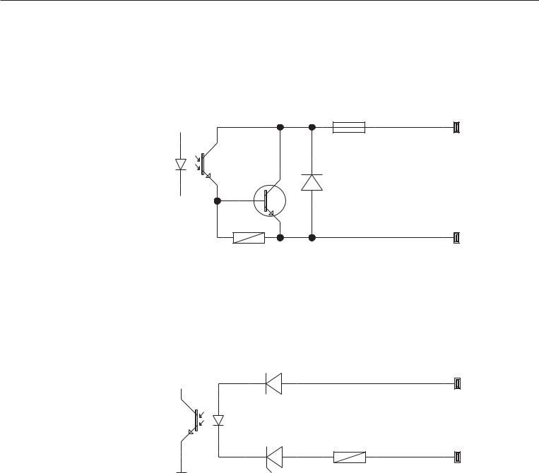
Example: Basic Circuit Diagram
|
|
0.2A |
OUTx_high |
LV1 |
|
|
30V |
|
|
1 |
4 |
|
|
2 3
OUTx_low
LV1
Inputx_high
LV2
4 1
3 |
2 |
Inputx_low |
LV2 |
|
|
|
10
Pin Assignment Charts
COM1
–RS-232 interface: YDO01M-232 (Option A11), YDO01M-232CLK (A31): Pin assignments in the 8-contact terminal screw strip on the interface module:
Pin |
1: +12 V: Supply voltage for |
|
|
|
Sartorius printers |
Pin |
2: |
Reset_Out |
|
|
(peripheral device restart) |
Pin |
3: |
+5 V Out |
Pin |
4: |
Ground (GND) |
Pin |
5: Clear to send (CTS) |
|
Pin |
6: Data terminal ready (DTR) |
|
Pin |
7: |
Data input (R+D) |
Pin |
8: |
Data output (T+D) |
UniCOM
–Pin assignments in the two 10-contact terminal screw strips on the interface module:
RS-232 interface: YDO01M-232CO (Option A1):
Pin |
1: |
Clear to send (CTS) |
Pin |
2: |
Data terminal ready (DTR) |
Pin |
3: |
Data input (R+D) |
Pin |
4: |
Data output (T+D) |
Pin |
5: |
Ground (GND) |
Pin |
6: |
Universal IN |
Pin |
7: |
Control output: “lighter" |
Pin |
8: |
Control output: “equal" |
Pin |
9: |
Control output: “heavier" |
Pin 10: |
Control output: “set" |
|
Pin 11: |
+12 V: Supply voltage for |
|
Sartorius printers |
Pin 12: |
Reset_Out |
|
(peripheral device restart) |
Pin 13: |
Ground (GND) |
Pin 14: |
Ground (GND) |
Pin 15: |
+5 V output |
Pin 16: |
+5 V switched |
|
(e.g., for bar code scanner) |
Pin 17: |
Ground (GND) |
Pin 18: |
Ground (GND) |
Pin 19: |
Not connected |
Pin 20: |
Ext. supply voltage output |
|
+15V to 25V |
Digital I/O interface: YDO01M-IO (Option A5):
Pin 1: External output port 5: low Pin 2: External output port 5: high Pin 3: External output port 4: low Pin 4: External output port 4: high Pin 5: External output port 3: low Pin 6: External output port 3: high Pin 7: External output port 2: low Pin 8: External output port 2: high Pin 9: External output port 1: low Pin 10: External output port 1: high Pin 11: Input port 5: low
Pin 12: Input port 5: high Pin 13: Input port 4: low Pin 14: Input port 4: high Pin 15: Input port 3: low Pin 16: Input port 3: high Pin 17: Input port 2: low Pin 18: Input port 2: high Pin 19: Input port 1: low Pin 20: Input port 1: high
– Pin assignments in the two terminal screw strips on the interface module:
1 2 3 4 5 6
YDO01M-485: RS-485 mode (Option A2):
Pin |
1: |
Data + (T+D-R+D+) |
Pin |
2: |
Data - (T+D-R+D-) |
Pin |
3: |
Not connected |
Pin |
4: |
Not connected |
Pin |
5: |
Signal ground, electrically |
|
|
isolated (GND_GALV) |
Pin |
6: |
Signal ground, electrically |
|
|
isolated (GND_GALV) |
Pin 11: |
Ext. supply voltage input |
|
|
|
+15V to 25V * |
Pin 12: |
Ext. supply voltage input |
|
|
|
+15V to 25V * |
Pin 13: |
Ground (GND) * |
|
Pin 14: |
Ground (GND) * |
|
1 |
2 |
3 |
4 |
5 |
6 |
YDO01M-485: RS-422 mode |
|||||
(Option A3): |
|
|
|||
Pin |
1: |
|
Data output + (T+D+) |
||
Pin |
2: |
|
Data output - (T+D-) |
||
Pin |
3: |
|
Data input + (R+D+) |
||
Pin |
4: |
|
Data input - (R+D-) |
||
Pin |
5: |
|
Signal ground, electrically |
||
|
|
|
isolated (GND_GALV) |
||
Pin |
6: |
|
Signal ground, electrically |
||
|
|
|
isolated (GND_GALV) |
||
Pin 11: |
|
Ext. supply voltage input |
|||
|
|
|
+15V to 25V * |
||
Pin 12: |
|
Ext. supply voltage input |
|||
|
|
|
+15V to 25V * |
||
Pin 13: |
|
Ground (GND) * |
|||
Pin 14: |
|
Ground (GND) * |
|||
* = Not electrically isolated
YDA01M-20MA (current/voltage interface):
6-pin terminal screw strip on the interface module
1 |
2 |
3 |
4 |
5 |
6 |
Pin |
1: |
|
I_out (+) |
||
|
|
|
for current interface |
||
|
|
|
(0/4 to 20/24 mA) |
||
Pin |
2: |
|
I_in (–) |
|
|
|
|
|
for current interface |
||
|
|
|
(0/4 to 20/24 mA) |
||
Pin |
3: |
|
V_out (+) |
||
|
|
|
for voltage interface, |
||
|
|
|
0V to + 10V |
||
Pin |
4: |
|
V_in (–) |
|
|
|
|
|
for voltage interface, |
||
|
|
|
0V to + 10V |
||
Pin |
5: |
|
GND, electrically isolated |
||
|
|
|
(electrically isolated ground) |
||
Pin |
6: |
|
GND, electrically isolated |
||
|
|
|
(electrically isolated ground) |
||
Pin assignment of the Ethernet interface (RJ45)
YDO01M-EN (Option B9):
Pin 1: |
TxD+ |
Pin 2: |
TxD- |
Pin 3: |
RxD+ |
Pin 4: |
Not in use |
Pin 5: |
Not in use |
Pin 6: |
RxD- |
Pin 7: |
Not in use |
Pin 8: |
Not in use |
Chassis: |
GND |
11

Configuring COM1 and UniCOM
Operating menu overview for the COM1 and UniCOM interfaces
(see also “Operating Menu Overview" in the chapter entitled “Configuration" in the Midrics operating instructions).
Appl |
|
|
|
|
|
|
|
|
|
|
|
|
|
|
|
|
|
|
|
|
|
|
|
|
|
||
Fn-Key |
|
|
|
|
|
|
|
|
|
|
|
|
|
|
|
|
|
|
|
|
|
|
|
|
|
||
Setup |
|
|
WP-1 |
|
|
|
|
|
|
|
|
|
|
|
|
|
|
|
|
|
|
|
|
|
|
||
|
|
|
|
|
|
|
|
|
|
|
|
|
|
|
|
|
|
|
|
|
|
|
|
||||
|
|
|
COM1 |
|
|
|
OFF * |
|
|
|
|
|
|
|
|
|
|
|
|
|
|
|
|
|
|
||
|
|
|
|
|
|
|
|
|
|
|
|
|
|
|
|
|
|
|
|
|
|
|
|
||||
|
|
|
|
|
|
|
DATPROT |
|
|
SBI * |
|
|
|
|
|
|
|
|
|
|
|
|
|
||||
|
|
|
|
|
|
|
|
|
|
|
|
|
|
|
|
|
|
|
|
|
|
||||||
|
|
|
|
|
|
|
(data record) |
|
XBPI-232 |
|
|
|
|
|
|
|
|
|
|
|
|
|
|||||
|
|
|
|
|
|
|
|
|
|
|
|
|
|
|
|
|
|
|
|
|
|||||||
|
|
|
|
|
|
|
|
|
|
|
SMA |
|
|
|
|
|
|
|
|
|
|
|
|
|
|||
|
|
|
|
|
|
|
|
|
|
|
|
|
|
|
|
|
|
|
|
|
|
|
|
||||
|
|
|
|
|
|
|
Printer |
|
|
YDP01IS |
|
|
|
Line * |
|
|
|
|
|
|
|
|
|||||
|
|
|
|
|
|
|
|
|
|
|
|
|
|
|
|
|
|
|
|
||||||||
|
|
|
|
|
|
|
|
|
|
|
|
|
|
|
|
Label |
|
|
|
|
|
|
|
|
|||
|
|
|
|
|
|
|
|
|
|
|
|
|
|
|
|
|
|
|
|
|
|
|
|
||||
|
|
|
|
|
|
|
|
|
|
|
YDP02 |
|
Label, man. form feed |
|
|
|
|
|
|||||||||
|
|
|
|
|
|
|
|
|
|
|
|
|
|
|
|
|
|||||||||||
|
|
|
|
|
|
|
|
|
|
|
|
|
|
|
|
|
|
|
|
|
|
|
|
||||
|
|
|
|
|
|
|
|
|
|
|
|
|
|
|
|
|
|
|
|
|
|
|
|
||||
|
|
|
|
|
|
|
|
|
|
|
YDP03 |
|
|
|
|
|
|
|
|
|
|
|
|
|
|||
|
|
|
|
|
|
|
|
|
|
|
|
|
|
|
|
|
|
|
|
|
|
|
|
||||
|
|
|
|
|
|
|
|
|
|
|
YDP02IS |
|
|
Line * |
|
|
|
|
|
|
|
|
|||||
|
|
|
|
|
|
|
|
|
|
|
|
|
|
|
|
|
|
|
|
|
|||||||
|
|
|
|
|
|
|
|
|
|
|
|
|
|
|
|
Label |
|
|
|
|
|
|
|
|
|||
|
|
|
|
|
|
|
|
|
|
|
|
|
|
|
|
|
|
|
|
|
|
|
|
||||
|
|
|
|
|
|
|
|
|
|
|
UNI-PRI (universal printer) |
|
|
|
|
|
|
|
|
||||||||
|
|
|
|
|
|
|
|
|
|
|
|
|
|
|
|
|
|
|
|||||||||
|
|
|
|
|
|
|
|
|
|
|
YDP04IS |
|
|
Line * |
|
|
|
|
|
|
|
|
|||||
|
|
|
|
|
|
|
|
|
|
|
|
|
|
|
|
|
|
|
|
|
|||||||
|
|
|
|
|
|
|
|
|
|
|
|
|
|
|
|
Label |
|
|
|
|
|
|
|
|
|||
|
|
|
|
|
|
|
|
|
|
|
|
|
|
|
|
|
|
|
|
|
|
|
|
||||
|
|
|
|
|
|
|
|
|
|
|
|
|
|
|
|
Label, man. form feed |
|
|
|
|
|
||||||
|
|
|
|
|
|
|
|
|
|
|
|
|
|
|
|
|
|
|
|
|
|||||||
|
|
|
|
|
|
|
MEMORY |
|
|
YAM01IS (Alibi memory) |
|
|
|
|
|
|
|
|
|||||||||
|
|
|
|
|
|
|
|
|
|
|
|
|
|
|
|
|
|||||||||||
|
|
|
UniCOM |
|
|
OFF * |
|
|
|
|
|
|
|
|
|
|
|
|
|
|
|
|
|
|
|||
|
|
|
|
|
|
|
|
|
|
|
|
|
|
|
|
|
|
|
|
|
|
|
|||||
|
|
|
|
|
|
|
DATPROT |
|
|
SBI * |
|
|
|
|
|
|
|
|
|
|
|
|
|
||||
|
|
|
|
|
|
|
|
|
|
|
|
|
|
|
|
|
|
|
|
|
|
||||||
|
|
|
|
|
|
|
(data record) |
|
XBPI-232 |
|
|
|
|
|
|
|
|
|
|
|
|
|
|||||
|
|
|
|
|
|
|
|
|
|
|
|
|
|
|
|
|
|
|
|
|
|||||||
|
|
|
|
|
|
|
|
|
|
|
XBPI-485 |
|
|
|
|
|
|
|
|
|
|
|
|
|
|||
|
|
|
|
|
|
|
|
|
|
|
|
|
|
|
|
|
|
|
|
|
|
|
|
||||
|
|
|
|
|
|
|
|
|
|
|
SMA |
|
|
|
|
|
|
|
|
|
|
|
|
|
|||
|
|
|
|
|
|
|
|
|
|
|
|
|
|
|
|
|
|
|
|
|
|
|
|
||||
|
|
|
|
|
|
|
|
|
|
|
ETHERNET |
|
|
Source IP: 192.168.0.1 * |
|
|
|
|
|
||||||||
|
|
|
|
|
|
|
|
|
|
|
|
|
|
|
|
|
|
||||||||||
|
|
|
|
|
|
|
|
|
|
|
|
|
|
|
|
Source name |
|
|
|
|
|
|
|
|
|||
|
|
|
|
|
|
|
|
|
|
|
|
|
|
|
|
|
|
|
|
|
|
|
|
||||
|
|
|
|
|
|
|
|
|
|
|
|
|
|
|
|
Listen port: 49155 * |
|
|
|
|
|
||||||
|
|
|
|
|
|
|
|
|
|
|
|
|
|
|
|
|
|
|
|
|
|||||||
|
|
|
|
|
|
|
|
|
|
|
|
|
|
|
|
Subnet mask: 255.255.255.0 * |
|
|
|
|
|
||||||
|
|
|
|
|
|
|
|
|
|
|
|
|
|
|
|
|
|
|
|
|
|||||||
|
|
|
|
|
|
|
|
|
|
|
|
|
|
|
|
Gateway IP: 0.0.0.0 * |
|
|
|
|
|
||||||
|
|
|
|
|
|
|
|
|
|
|
|
|
|
|
|
|
|
|
|
|
|||||||
|
|
|
|
|
|
|
|
|
|
|
|
|
|
|
|
DNS IP: 0.0.0.0 * |
|
|
|
|
|
||||||
|
|
|
|
|
|
|
|
|
|
|
|
|
|
|
|
|
|
|
|
|
|||||||
|
|
|
|
|
|
|
|
|
|
|
|
|
|
|
|
Target IP: 0.0.0.0 * |
|
|
|
|
|
||||||
|
|
|
|
|
|
|
|
|
|
|
|
|
|
|
|
|
|
|
|
|
|||||||
|
|
|
|
|
|
|
|
|
|
|
|
|
|
|
|
Target port: 49155 * |
|
|
|
|
|
||||||
|
|
|
|
|
|
|
|
|
|
|
|
|
|
|
|
|
|
|
|
|
|||||||
|
|
|
|
|
|
|
|
|
|
|
|
|
|
|
|
Protocol |
|
|
TCP * |
|
|
|
|
|
|||
|
|
|
|
|
|
|
|
|
|
|
|
|
|
|
|
|
|
|
|
|
|
|
|||||
|
|
|
|
|
|
|
|
|
|
|
|
|
|
|
|
|
|
|
|
UDP |
|
|
|
|
|
||
|
|
|
|
|
|
|
|
|
|
|
|
|
|
|
|
|
|
|
|
|
|
|
|
|
|||
|
|
|
|
|
|
|
|
|
|
|
|
|
|
|
|
Mode |
|
|
SBI (server)-SRV* |
|
|
6.1. |
|
Data output manual/automatic |
|||
|
|
|
|
|
|
|
|
|
|
|
|
|
|
|
|
|
|
|
|
|
|
|
|
|
|
6.1.1 |
Manual without stability |
|
|
|
|
|
|
|
|
|
|
|
|
|
|
|
|
|
|
|
|
|
|
|
|
|
|
||
|
|
|
|
|
|
|
|
|
|
|
|
|
|
|
|
|
|
|
|
|
|
|
|
|
|
6.1.2 * Manual after stability |
|
|
|
|
|
|
|
|
|
|
|
|
|
|
|
|
|
|
|
|
|
|
|
|
|
|
|
||
|
|
|
|
|
|
|
|
|
|
|
|
|
|
|
|
|
|
|
|
|
|
|
|
|
|
6.1.4 |
Automatic without stability |
|
|
|
|
|
|
|
|
|
|
|
|
|
|
|
|
|
|
|
|
|
|
|
|
|
|
||
|
|
|
|
|
|
|
|
|
|
|
|
|
|
|
|
|
|
|
|
|
|
|
|
|
|
6.1.5 |
Automatic with stability |
|
|
|
|
|
|
|
|
|
|
|
|
|
|
|
|
|
|
|
|
|
|
|
|
|
|
||
|
|
|
|
|
|
|
|
|
|
|
|
|
|
|
|
|
|
|
|
|
|
|
|
|
|
6.1.7 Print log for PC |
|
|
|
|
|
|
|
|
|
|
|
|
|
|
|
|
|
|
|
|
|
|
|
|
|
|
|
||
|
|
|
|
|
|
|
|
|
|
|
|
|
|
|
|
|
|
|
|
|
|
|
|
7.2. |
|
Output: line format |
|
|
|
|
|
|
|
|
|
|
|
|
|
|
|
|
|
|
|
|
|
|
|
|
|
|
|||
|
|
|
|
|
|
|
|
|
|
|
|
|
|
|
|
|
|
|
|
|
|
|
|
|
|
7.2.1 For raw data: 16 characters |
|
|
|
|
|
|
|
|
|
|
|
|
|
|
|
|
|
|
|
|
|
|
|
|
|
|
|
||
|
|
|
|
|
|
|
|
|
|
|
|
|
|
|
|
|
|
|
|
|
|
|
|
|
|
7.2.2 * For other apps: 22 characters |
|
|
|
|
|
|
|
|
|
|
|
|
|
|
|
|
|
|
|
|
|
|
|
|
|
|
|
||
|
|
|
|
|
|
|
|
|
|
|
|
|
|
|
|
|
|
|
|
SBI-C/S |
|
|
6.1. |
|
Data output manual/automatic |
||
|
|
|
|
|
|
|
|
|
|
|
|
|
|
|
|
|
|
|
|
(client) |
|
|
|
6.1.1 |
Manual without stability |
||
|
|
|
|
|
|
|
|
|
|
|
|
|
|
|
|
|
|
|
|
|
|
|
|||||
|
|
|
|
|
|
|
|
|
|
|
|
|
|
|
|
|
|
|
|
|
|
|
|
|
|
6.1.2 * Manual after stability |
|
|
|
|
|
|
|
|
|
|
|
|
|
|
|
|
|
|
|
|
|
|
|
|
|
|
|
||
|
|
|
|
|
|
|
|
|
|
|
|
|
|
|
|
|
|
|
|
|
|
|
|
|
|
6.1.4 |
Automatic without stability |
|
|
|
|
|
|
|
|
|
|
|
|
|
|
|
|
|
|
|
|
|
|
|
|
|
|
||
|
|
|
|
|
|
|
|
|
|
|
|
|
|
|
|
|
|
|
|
|
|
|
|
|
|
6.1.5 |
Automatic with stability |
|
|
|
|
|
|
|
|
|
|
|
|
|
|
|
|
|
|
|
|
|
|
|
|
|
|
||
|
|
|
|
|
|
|
|
|
|
|
|
|
|
|
|
|
|
|
|
|
|
|
|
|
|
6.1.7 Print log for PC |
|
|
|
|
|
|
|
|
|
|
|
|
|
|
|
|
|
|
|
|
|
|
|
|
|
|
|
||
|
|
|
|
|
|
|
|
|
|
|
|
|
|
|
|
|
|
|
|
|
|
|
|
6.3. |
|
Time-dependent autom. output |
|
|
|
|
|
|
|
|
|
|
|
|
|
|
|
|
|
|
|
|
|
|
|
|
|
|
|||
|
|
|
|
|
|
|
|
|
|
|
|
|
|
|
|
|
|
|
|
|
|
|
|
|
|
6.3.1 * 1 display cycle |
|
|
|
|
|
|
|
|
|
|
|
|
|
|
|
|
|
|
|
|
|
|
|
|
|
|
|
||
|
|
|
|
|
|
|
|
|
|
|
|
|
|
|
|
|
|
|
|
|
|
|
|
|
|
6.3.2 |
2 display cycles |
|
|
|
|
|
|
|
|
|
|
|
|
|
|
|
|
|
|
|
|
|
|
|
|
|
|
||
|
|
|
|
|
|
|
|
|
|
|
|
|
|
|
|
|
|
|
|
|
|
|
|
|
|
6.3.4 |
10 display cycles |
|
|
|
|
|
|
|
|
|
|
|
|
|
|
|
|
|
|
|
|
|
|
|
|
|
|
||
|
|
|
|
|
|
|
|
|
|
|
|
|
|
|
|
|
|
|
|
|
|
|
|
|
|
6.3.7 |
100 display cycles |
|
|
|
|
|
|
|
|
|
|
|
|
|
|
|
|
|
|
|
|
|
|
|
|
|
|
||
|
|
|
|
|
|
|
|
|
|
|
|
|
|
|
|
|
|
|
|
|
|
|
|
7.2. |
|
Output: line format |
|
|
|
|
|
|
|
|
|
|
|
|
|
|
|
|
|
|
|
|
|
|
|
|
|
|
|||
|
|
|
|
|
|
|
|
|
|
|
|
|
|
|
|
|
|
|
|
|
|
|
|
|
|
7.2.1 For raw data: 16 characters |
|
|
|
|
|
|
|
|
|
|
|
|
|
|
|
|
|
|
|
|
|
|
|
|
|
|
|
||
|
|
|
|
|
|
|
|
|
|
|
|
|
|
|
|
|
|
|
|
xBPI |
|
|
|
7.2.2 * For other apps: 22 characters |
|||
|
|
|
|
|
|
|
|
|
|
|
|
|
|
|
|
|
|
|
|
|
|
|
|||||
|
|
|
|
|
|
|
|
|
|
|
|
|
|
|
|
|
|
|
|
|
|
|
|
|
|||
|
|
|
|
|
|
|
|
|
|
|
|
|
|
|
|
|
|
|
|
|
|
|
|
|
|||
|
|
|
|
|
|
|
|
|
|
|
|
|
|
|
|
|
|
|
|
SMA |
|
|
|
|
|
||
|
|
|
|
|
|
|
|
|
|
|
|
|
|
|
|
|
|
|
|
|
|
|
|
|
|||
|
|
|
|
|
|
|
|
|
|
|
|
|
|
|
|
|
|
|
|
Modbus/TCP |
|
|
|
|
|
||
|
|
|
|
|
|
|
|
|
|
|
|
|
|
|
|
|
|
|
|
|
|
|
|
|
|||
12

Setup |
|
|
UniCOM |
|
|
|
Printer |
|
|
|
|
YDP01IS |
|
|
Line * |
||||
|
|
|
|
|
|
|
|
|
|
|
|
|
|
|
|
|
|
|
Label |
|
|
|
|
|
|
|
|
|
|
|
|
|
|
|
|
|
|
|
|
|
|
|
|
|
|
|
|
|
|
|
|
|
|
YDP02 |
|
|
Label, man. form feed |
||
|
|
|
|
|
|
|
|
|
|
|
|
|
|
|
|
||||
|
|
|
|
|
|
|
|
|
|
|
|
|
|
|
|
|
|||
|
|
|
|
|
|
|
|
|
|
|
|
|
|
|
|
|
|||
|
|
|
|
|
|
|
|
|
|
|
|
|
|
YDP03 |
|
|
|
||
|
|
|
|
|
|
|
|
|
|
|
|
|
|
|
|
|
|||
|
|
|
|
|
|
|
|
|
|
|
|
|
|
YDP02IS |
|
|
|
|
Line * |
|
|
|
|
|
|
|
|
|
|
|
|
|
|
|
|
|
|
||
|
|
|
|
|
|
|
|
|
|
|
|
|
|
|
|
|
|
|
Label |
|
|
|
|
|
|
|
|
|
|
|
|
|
|
|
|
|
|
|
|
|
|
|
|
|
|
|
|
|
|
|
|
|
|
UNI-PRI (universal printer) |
|||||
|
|
|
|
|
|
|
|
|
|
|
|
|
|
||||||
|
|
|
|
|
|
|
|
|
|
|
|
|
|
YDP04IS |
|
|
|
Line * |
|
|
|
|
|
|
|
|
|
|
|
|
|
|
|
|
|
|
|||
|
|
|
|
|
|
|
|
|
|
|
|
|
|
|
|
|
|
|
Label |
|
|
|
|
|
|
|
|
|
|
|
|
|
|
|
|
|
|
|
|
|
|
|
|
|
|
|
|
|
|
|
|
|
|
|
|
|
|
|
Label, man. form feed |
|
|
|
|
|
|
|
|
|
|
|
|
|
|
|
|
|
|
|
|
|
|
|
|
|
|
|
|
MEMORY |
|
|
|
YAM01IS (Alibi memory) |
|||||||
|
|
|
|
|
|
|
|
|
|
||||||||||
|
|
|
|
|
|
|
|
ANALOG (analog interface) |
|
|
|
||||||||
|
|
|
|
|
|
|
|
|
|
||||||||||
|
|
|
CTRL IO: |
|
|
|
CTR INP: |
|
|
8. 4. x |
TTL; for YDO01M-232CO, Option A1 |
||||||||
|
|
|
Control |
|
|
Control inputs |
|
8. 17. x |
Electrically isolated; for |
||||||||||
|
|
|
|
|
|
||||||||||||||
|
|
|
inputs/ |
|
|
|
|
|
|
|
|
to |
YDO01M-IO, Option A5 |
||||||
|
|
|
outputs |
|
|
|
|
|
|
|
|
8 . 21. x |
|
|
|
||||
|
|
|
|
|
|
|
|
|
|
|
|
|
|
||||||
|
|
|
|
|
|
|
|
CTR OUT: |
|
|
8. 24. x |
Electrically isolated; for |
|||||||
|
|
|
|
|
|
|
|
|
|||||||||||
|
|
|
|
|
|
|
|
Control |
|
to |
YDO01M-IO, Option A5 |
||||||||
|
|
|
|
|
|
|
|
||||||||||||
|
|
|
|
|
|
|
|
outputs |
|
8. 28. x |
|
|
|
||||||
|
|
|
|
|
|
|
|
|
|
|
|||||||||
*= Factory setting
13
Configuring the Interface
You can configure the UniCOM universal data interface for the required operating state (connection of a peripheral device).
The diagram on the preceding page shows the relevant section of the operating menu.
For additional information, see the chapter entitled “Settings" in the Midrics operating instructions.
RS-485/RS-422 Interface
If the PCB is configured for use in the RS-422 operating mode, you can select the SBI, XBPI-232, or SMA menu item.
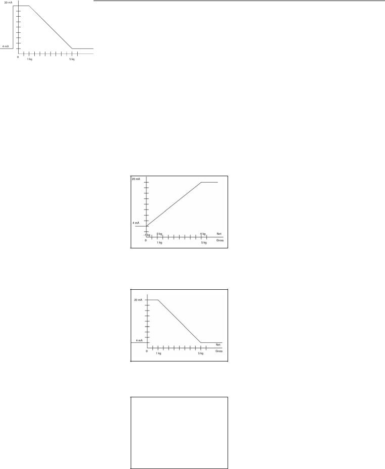
YDA01M-20MA Analog Interface
You can configure the following parameters in the operating menu:
–Output value (menu line 8.12): 8.12.1: Net value
(factory setting) 8.12.2: Gross value
–Error display (menu line 8.13): 8.13.1: High level (20 mA)
(factory setting) 8.13.2: Low level (0/4 mA):
5V on this interface during operation.
–Output mode (menu line 8.14): 8.14.1: Zero to maximum capacity
(factory setting)
8.14.2: Minimum/maximum values
–Output of minimum/maximum values (menu line 8.15):
8.15.1: Min. (0/4 mA) input in kg 8.15.2: Max. (20 mA) input in kg
By selecting min./max. values you can specify the weighing range for output on the 0/4 to 20mA (0 to 10 V) interface. This selection applies as well to an SBI scale, but only for the net value.
Input of min. and max. values is always in kilograms. You can enter negative values if desired. You can also enter a min. value that is higher than the max. value, to effect falling current output.
Examples:
Rising current curve
Min. value, net: -1 kg
Max. value, net: 4 kg
Falling current curve for XBPI scales Min. value: 5 kg
Max. value: 1 kg
Falling current curve for SBI scales Min. value: 5 kg
Max. value: 1 kg
Ethernet interface
In the “UNICOM” menu, select “ETHERNET” to enter numerical values under Source IP, ListenPort, etc. Under Source name, both letters and numbers can be used. A maximum of 15 characters can be entered. Enter either a source name or a source IP address (not both).
Port numbers
Validity range: 0 – 65535
Since many of the ports up to 49150 have already been allocated, we recommend using port numbers above 49150. This does not apply to Modbus/TCP, because the following port number applies here: 502 (see the fieldbus brochure for details)
14

Ethernet interface: Initialization
Display: Initialization completed Once initialization of the Ethernet
module has been completed successfully, the “ ” symbol is displayed.
Network module initialized
If initialization was not successful, no symbol is displayed. The symbol provides no information about the connection status in relation to the network.
TCP connections:
In the SBI-C/S operating mode, Midrics always terminates the connection independently, after 1 second.
In the other operating modes
(SBI-SRV, SMA, XBPI, ModBus/TCP) the connection is maintained until it is disconnected by the PC (client). It is only possible to establish one connection at a time.
Ethernet interface: Features
Source IP: IP address of the Midrics indicator
If the address 0.0.0.0 is selected, you need to enter a name under
“Source name.” In this case, the IP address should be dynamically allocated by a DHCP server located within the network.
Source name: |
This parameter is alternative to the “Source IP” input. A name that is up |
|
to 15 characters in length and serves to identify the Midrics can be entered. |
|
In this case, the address 0.0.0.0 must be selected as the source IP. The name |
|
is announced to the domain name service (DNS) if |
|
– an IP address has been entered under DNS IP |
|
or |
|
– an IP address has been allocated over DHCP. |
Device port: |
Number of the port on which the Midrics listens for server operation. |
Subnet mask: |
IP address mask for the activation of IP addresses in a subnet. If the mask |
|
is to be allocated using a DHCP server, 0.0.0.0 must be entered. |
Gateway IP: |
IP address of a gateway |
|
Address of desired server located in another network using target IP. If the IP |
|
address is to be allocated dynamically using a DHCP server, 0.0.0.0 must be |
|
entered. |
Target IP: |
Address of the server that is to receive the Midrics data. |
|
Important for operation of the Midrics as a client if the SBI mode has been |
|
selected in combination with automatic data output. When using UDP, |
|
an IP address must also be entered here. |
Target port: |
Port number on which a server with the target IP listens in order to receive |
|
data from the Midrics. |
Protocol: |
Select the transport protocol to be used to transmit data over Ethernet. |
|
Please select either: |
|
– TCP, connection-oriented with high data security |
|
or |
|
– UDP, connectionless (does not effect Modbus/TCP) |
Mode: |
Select the data format that contains the user data embedded in TCP or UDP |
|
(e.g. SMA is tunnelled over Ethernet using TCP or UDP). |
|
With the SBI-SRV, XBPI and SMA protocols, the Midrics is always to be seen |
|
as a server. Under SBI-C/S, the Midrics is simultaneously a server and a client. |
|
Client mode is activated when the p [Print] button is pressed or the data |
|
output parameter has been set to “automatic”. For the OPC mode, set the |
|
menu code for “SBI server.” In all other instances, the Midrics is a server. |
|
Under ModBus/TCP, the Midrics is always active as a server (also see the field |
|
bus brochure). |
Power-on |
|
response: |
If the interface module is active, the display of the weight value may be |
|
delayed by up to 20 seconds. |
15

Synchronization
Data communication between the display and control unit and a computer takes the form of messages (“telegrams") made up of ASCII code. For error-free data communication, the settings for baud rate, parity, handshake mode and character format must be the same at both ends.
You can configure the interface settings in the Setup menu so that they match those of the computer. You can also define parameters in the indicator to make data output dependent on various conditions. The conditions that can be configured are listed in the descriptions of the application programs (see operating instructions for the Midrics scale).
If you do not connect a peripheral device to the display and control unit's interface port, this will not generate an error message.
Handshake
The weighing instrument interface (Sartorius Balance Interface = SBI) has transmit and receive buffers. You can define the handshake parameter in the display and control unit's Setup menu:
–Hardware handshake (CTS/DTR)
–Software handshake (XON, XOFF)
Hardware Handshake
Hardware handshake with a 4-wire interface: 1 more character can be transmitted after CTS (clear-to-send).
Software Handshake
The software handshake is controlled via XON and XOFF. When a device is switched on, XON must be transmitted to enable a connected device to communicate.
The data transmission sequence is as follows:
Scale |
––– byte –––> |
Computer |
(trans- |
––– byte –––> |
(receiving |
mitting |
|
device) |
device) |
––– byte –––> |
|
|
|
|
|
––– byte –––> |
|
|
<–– XOFF ––– |
|
|
––– byte –––> |
|
|
––– byte –––> |
|
|
... |
|
|
(Pause) |
|
|
... |
|
|
<–– XON ––– |
|
|
––– byte –––> |
|
|
––– byte –––> |
|
|
––– byte –––> |
|
|
––– byte –––> |
|
Transmitting Device
Once XOFF has been received, it prevents further transmission of characters. When XON is received, it re-enables the transmitting device to send data.
Receiving Device
To prevent too many control commands from being received at one time, XON is not transmitted until the buffer is almost empty.
16

Data Interfaces
Configuring the Data Interface as a COM Port (datprot)
Configure the interface as a COM port in the Setup menu under COM1 or UniCOM, under the “Data Protocol" (datprot) menu item.
SBI Communication
This is a simple ASCII interface.
Data output is configured under menu lines 6.1 and 6.3:
–Manual output of displayed value with or without stability (menu items 6.1.1 and 6.1.2)
–Automatic output of displayed value with or without stability (menu items 6.1.4 and 6.1.5) at intervals defined by display updates. The number of display updates comprising an output interval is configured under menu item 6.3.
–Output of a configurable printout. Output is linked to the Printout (prtprot) settings.
If you do not activate and configure a user-definable data record, the printout simply contains the current value displayed on the indicator (weight with unit, calculated value, alphanumeric display).
SMA Communication
Standardized communications protocol of the Scale Manufacturers Association
Data Input Format (Commands)
You can connect a computer to your display and control unit to send commands controlling weighing instrument functions and applications via the interface port.
All commands use the same format (data input format) starting with the ESC character (ASCII 27) and ending with a carriage return (CR; ASCII 13) and a line feed (LF; ASCII 10). The total length of a command is anywhere from 4 characters (1 command character between the start and end described above) to 7 characters (4 command characters).
The table below shows the available command characters; each command must be flanked by the start and end characters as described above. Example: The command character for output is “P" (“transmit readout value"). The string “ESC P CR LF" triggers this command.
Command Meaning
K Weighing mode 1
L Weighing mode 2
M Weighing mode 3
N Weighing mode 4
OBlock keys
POutput readout to data interface
RUnblock keys
TTare and zero (combination tare function)
f3_ Zero (see also the “kZE_" command)
f4_ Tare (without zeroing; as the “kT_" command)
kF1_ F1: Trigger k key function
kF2_ F2: Trigger c key function (Midrics 2 only)
kF3_ F3: Trigger r key function (Midrics 2 only)
kF4_ F4: Trigger O key function (Midrics 2 only)
kF5_ F5: Trigger w key function (Midrics 2 only)
Command Meaning
kF6_ F6: Trigger I key function (Midrics 2 only)
KF7_ d key
kCF_ CF: Trigger c key function (Midrics 2 only)
kP_ Trigger p key function Output to printer port
kT_ Trigger T key function (tare)
kZE_ Trigger ( key function (zero)
x1_ Output model designation
of active weighing instrument. Example: “LP6200S-0C"
x2_ Output serial number
of active weighing instrument; Example: “0012345678"
x3_ Output software version
of active weighing instrument; Example: “00-20-04"
z1_ Activate input for printout header 1
z2_ Activate input for printout header 2
txx...x_ xx...x: Enter letters Length acc. to input (Midrics 2 only)
The ASCII code for the “underline" character is 95.
Format for entering printout header lines: “ESC z x a ... a _ CR LF" where x=(header line) 1 or 2, and a ... a: = up to 20 characters of text, followed by the “underline" character, carriage return and line feed.
17

Data Output Format
Each line in a print job can contain up to 22 characters (up to 20 printable characters plus two control characters). The first 6 characters, called the “data header", identify the subsequent value. You can suppress the header under menu item 7.2 in the “Printouts" menu; in this case, the print job has up to
16 characters (up to 14 printable characters plus two control characters).
Examples: |
|
Without data header |
+ |
235 pcs |
|
Qnt + |
235 pcs With data header |
|
Display segments that are not activated are output as spaces. Values with no decimal point are output without a decimal point.
Data Output Format with 16 Characters (without Data Header)
Normal Operation:
Pos. 1 2 3 4 5 6 7 8 9 101112131415 16
|
+ * |
D D D D D D D D * |
U U U CR LF |
or |
- * |
D D D D D D D D * |
U U U CR LF |
or |
* * |
* * * * * * * * * |
* * * CR LF |
+-: Plus or minus sign *: Space
D:Digit or letter (max. 7 characters plus decimal point)
U:Unit symbol (1 to 3 letters, followed by
0 to 2 spaces) CR: Carriage return LF: Line feed
Special Codes:
Pos. |
1 |
2 |
3 |
4 |
5 |
6 |
7 |
8 |
9 |
101112131415 16 |
|
* |
* |
* |
* |
* |
* |
– |
– |
* |
* * * * * CR LF |
or |
* |
* |
* |
* |
* |
* |
H |
* |
* |
* * * * * CR LF |
or |
* |
* |
* |
* |
* |
* |
H H * |
* * * * * CR LF |
||
or |
* |
* |
* |
* |
* |
* |
L |
* |
* |
* * * * * CR LF |
or |
* |
* |
* |
* |
* |
* |
L |
L |
* |
* * * * * CR LF |
or |
* |
* |
* |
* |
* |
* |
C |
* |
* |
* * * * * CR LF |
*: |
|
Space |
|
|
|
|
|
|
|
|
– –: |
|
Final readout mode |
|
|
||||||
H:Overload
HH Overload in Checkweighing
L:Underload
LL Underload in Checkweighing
C:Calibration/adjustment
Error Codes: |
|
|
|
|
|
|
|
|
|
|||
Pos. |
1 |
2 |
3 |
4 |
5 |
6 |
7 |
8 |
9 |
10111213141516 |
|
|
|
* |
* |
* |
E |
r |
r |
* |
* |
# |
# * * * * CRLF |
|
|
or |
* * * E r r * # # # * * * * CR LF |
|||||||||||
*: |
Space |
|
|
|
|
|
|
|
|
|
||
#: |
Error code number (2 or 3 digits) |
|||||||||||
Example (output of value: +1255.7 g): |
||||||||||||
Pos. |
1 |
2 |
3 |
4 |
5 |
6 |
7 |
8 |
9 |
10111213141516 |
|
|
|
+ |
* |
* |
* |
1 |
2 |
5 |
5 . |
7 * g * * CRLF |
|||
Position 1: |
|
|
|
Plus or minus sign or space |
||||||||
Position 2: |
|
|
|
Space |
|
|
|
|
||||
Positions 3-10: |
|
Weight value with decimal point; leading |
||||||||||
|
|
|
|
|
|
zeros are output as spaces. |
||||||
Position 11: |
|
|
Space |
|
|
|
|
|||||
Positions 12 - 14: |
Unit symbol or space |
|||||||||||
Position 15: |
|
|
Carriage return |
|||||||||
Position 16: |
|
|
Line feed |
|
|
|
||||||
Data Output Format with 22 Characters (with Data Header)
Normal Operation:
Pos. |
1 |
2 |
3 |
4 |
5 |
6 |
7 |
8 |
9 |
10111213141516171819202122 |
|
|
I |
I |
I |
I |
I |
I |
+ |
* |
D |
D D D D D D D * |
U U U CRLF |
or |
I |
I |
I |
I |
I |
I |
- |
* |
D |
D D D D D D D * |
U U U CRLF |
or |
* |
* |
* |
* |
* |
* |
* |
* |
* |
* * * * * * * * |
* * * CRLF |
I: ID code character, right-justified with spaces Space +-: Plus or minus sign
*: Space
A:Digit or letter (max. 7 characters plus decimal point)
U: Unit symbol (1 to 3 letters, followed by 0 to 2 spaces) CR: Carriage return
LF: Line feed
Special Codes:
Pos. |
1 |
2 |
3 |
4 |
5 |
6 |
7 |
8 |
9 |
10111213141516171819202122 |
|||||||||||
|
S |
t |
a |
t |
* |
* |
* |
* |
* |
* |
* |
* |
– |
– |
* |
* |
* |
* |
* |
* |
CRLF |
or |
S |
t |
a |
t |
* |
* |
* |
* |
* |
* |
* |
* |
H |
* |
* |
* |
* |
* |
* |
* |
CRLF |
or |
S |
t |
a |
t |
* |
* |
* |
* |
* |
* |
* |
* |
H |
H |
* |
* |
* |
* |
* |
* |
CRLF |
or |
S |
t |
a |
t |
* |
* |
* |
* |
* |
* |
* |
* |
L |
* |
* |
* |
* |
* |
* |
* |
CRLF |
or |
S |
t |
a |
t |
* |
* |
* |
* |
* |
* |
* |
* |
L |
L |
* |
* |
* |
* |
* |
* |
CRLF |
or |
S |
t |
a |
t |
* |
* |
* |
* |
* |
* |
* |
* |
C |
* |
* |
* |
* |
* |
* |
* |
CRLF |
*: to 2 spaces |
– –: Final readout mode |
H: Overload |
HH: Overload in Checkweighing |
L: Underload |
LL: Underload in Checkweighing |
C: Calibration/adjustment |
|
18

Data Interfaces
GMP-compliant Printouts |
Examples of GMP headers and one example of a GMP footer are shown in the following: |
|||
When the corresponding menu item is |
|
|
|
Dotted line |
active, the measured result is bracketed |
------------------- |
|
|
|
on the printout by a GMP header and |
14.01.2007 |
09:43 |
Date and time 1) |
|
a GMP footer (GMP: “Good Manufac- |
Typ |
|
MIS2 |
Midrics model |
turing Practice"). |
Ser.no. |
|
12345678 |
Midrics serial no. |
The GMP header precedes the first |
Vers. |
1.1007.12.1 |
Software release for application |
|
measured result. The GMP footer is |
BVers. |
|
01-25-01 |
Software release for basic version |
printed either after each measured |
------------------- |
|
|
Dotted line |
result (“ISO/GLP/GMP: For 1 application |
|
|
|
|
result," menu item 7.11.2), or after the |
|
|
|
GMP footer: |
last result in a series of measurements |
|
|
|
|
(“ISO/GMP/GLP: For several application |
------------------- |
|
|
Dotted line |
results," menu item 7.11.3). To end a |
14.01.2007 |
09:45 |
Date and time 1) |
|
series of measured results, press and |
Name: |
|
|
Field for operator signature |
hold the p key (> 2 sec). |
|
|
|
Blank line |
In this case, the A symbol is displayed |
------------------- |
|
|
Dotted line |
after the GMP header is printed and |
|
|
|
|
remains in the display until the GMP |
1) YDO01M-232 (Option A31) required |
|
||
footer is printed. |
|
|||
At the end of a calibration procedure, the GMP printout is generated automatically.
If you use a label printer for GMP-com- pliant printouts and menu item 7.11.3 is active, the header and footer are printed on two different labels.
To generate GMP-compliant printouts on labels, select menu item 7.11.2.
19

Verwendungszweck |
Inhalt |
Der Datenausgang YD.01M-...
wird eingesetzt zum Einbau in Auswertegeräte und Komplettwaagen der Modelle Midrics MIS..., MW... als optionale Standard Schnittstelle COM1 oder Universal-Datenschnittstelle UniCOM.
Für COM1:
–YDO01M-232 (Option A11): Bidirektionale RS232-Datenschnittstelle. Das Modul YDO01M-232 ermöglicht: Den Anschluss verschiedener Drucker (YDP02IS, YDP03, YDP04IS, YDP12IS, Universal-Drucker), den Datenaustausch mit einem PC (SBI-, xBPIoder SMABetrieb).
–Anschluss eines Alibispeichers.
–Bluetooth Adapter YBT01.
–Zweitanzeige YRD02Z.
–USB-Adapterkabel zum PC-Anschluss über USB YCC01IS.
–YDO01M-232CLK »Clock«
(Option A31): wie Standard RS232, plus Datum/Uhrzeit.
Für UniCOM:
–YDO01M-232CO (Option A1):
wie Standard RS232 zusätzlich mit Digital In/Out (TTL/5V)
–YDO01M-485 (Optionen A2 und A3): Bidirektionale Datenschnittstelle, galvalnisch getrennt, wahlweise einsetzbar im RS422-Betrieb (Option A2) oder im RS485-Betrieb (Option A3).
Das Modul YDO01M-485 ermöglicht ein Netzwerk bis zu 32 MidricsWaagen/Indikatoren über XBPI-Bus.
–YDA01M-20MA (Option A9): Analogausgang, wahlweise einsetzbar als Stromschnittstelle (0/4 - 20mA, 0 - 24 mA) oder als Spannungsschnittstelle (0 bis 10 V).
Das Modul YDA01-20MA ermöglicht den Anschluss einer SPS oder einer externen Analoganzeige.
–YDO01M-IO (Option A5): Digitales Ein-/Ausgabemodul zum Anschluss von Midrics an externe Steuerungen.
–YDO01M-EN (Option B9): Ethernet-Schnittstelle (z.B. Anschluss an eine SPS oder einen PC).
|
Zeichenerklärung |
20 |
Verwendungszweck |
|
|
Folgende Symbole werden in dieser |
|
Inhalt |
|
|
Anleitung verwendet: |
20 |
||
§ |
steht vor Handlungsanweisungen |
21 |
Einbau in das Auswertegerät |
|
$ |
steht vor Handlungsanweisungen, |
21 |
COM1-Platine einsetzen |
|
22 |
UniCOM-Platine einsetzen |
|||
|
die nur unter bestimmten Vorausset- |
24 |
Schnittstellenkabel montieren |
|
|
zungen ausgeführt werden sollen |
25 |
Module konfigurieren: |
|
|
|
|||
> |
beschreibt das, was nach einer aus- |
|
YDO01M-485, YDA01M-20MA |
|
|
geführten Handlung geschieht |
27 |
YDO01M-IO: Spezifikationen |
|
! weist auf eine Gefahr hin |
||||
27 |
YDO01M-EN |
|||
|
|
28 |
Steckerbelegungsplan |
|
|
|
28 |
COM1 |
|
|
|
28 |
UniCOM |
|
|
|
29 |
Voreinstellungen COM1 und |
|
|
|
|
UniCOM |
|
|
|
33 |
Synchronisation |
|
|
|
34 |
Datenschnittstellen |
|
|
|
34 |
Dateneingangsformat (Kommandos) |
|
|
|
35 |
Datenausgangsformat |
|
|
|
36 |
GMP-Protokoll |
|
20
Einbau in das Auswertegerät
Einbau
Der Einbau des Schnittstellenmoduls in das Midrics-Auswertegerät (zusätzlich der Einbau der Kabelverschraubung und der Anschluss der Verbindungskabel an die Schraubklemmenleiste) ist nur dann erforderlich, wenn das Midrics-Auswertegerät nicht bereits werksseitig auf Kundenbestellung mit dem betreffenden Datenausgang ausgerüstet ist.
Hinweise:
§Der Einbau des Schnittstellenmoduls sollte nur von einem geschulten und autorisierten Sartorius-Fachmann ausgeführt werden.
§IP65-Schutz:
Entsprechendes Anschlusskabel mit Kabelverschraubung für das jeweilige Schnittstellenmodul verwenden (Zubehör).
!Vor Beginn der Arbeiten das Gerät vom Netz trennen.
!Bei unsachgemäßer Installation entfällt die Gewährleistung.
!IP65-Schutzart beeinflussende Arbeiten sind äußerst sorgfältig durchzuführen.
Die Kabeldurchführung (IP65-Schutz) für den Anschluss der Schnittstelle am Auswertegerät ist durch Blindstopfen verschlossen. Alle Arbeiten an der Kabelverschraubung sehr sorgfältig ausführen.
§ Frontplatte abnehmen: 4 Schrauben der Frontplatte lösen.
COM1-Platine einsetzen:
§ Befestigungsschraube herausdrehen
21

§ Abstandbolzen einschrauben
§ Platinenhalter einstecken
§Das Schnittstellenmodul (YDO01M-232 und YDO01M-232CLK) auf die Digitalplatine des Midrics-Auswertegerätes aufstecken. Dazu die Buchsenleisten des Schnittstellenmoduls in die korrespondierenden Steckerleisten der Digitalplatine stecken.
§Schnittstellenmodul mit der Schraube befestigen.
Die Schnittstellenmodule sind mit eigenen Schraubklemmenleisten ausgerüstet. Die Anschlusskabel an diese Klemmenleisten anschließen.
UniCOM-Platine einsetzen:
§2 Befestigungsschrauben herausdrehen
22
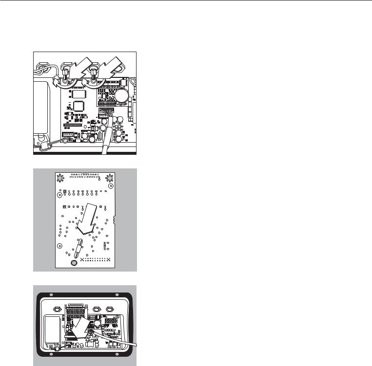
§ 2 Abstandbolzen einschrauben
§ Platinenhalter einstecken
§Das Schnittstellenmodul (YDO01M-232CO, YDO01M-485, YDA01M-20MA, YDO01M-EN) auf die Digitalplatine des Midrics-Auswertegerätes aufstecken. Dazu die Buchsenleisten des Schnittstellenmoduls in die korrespondierenden Steckerleisten der Digitalplatine stecken.
§Schnittstellenmodul mit der Schraube befestigen.
Die Schnittstellenmodule sind mit eigenen Schraubklemmenleisten ausgerüstet. Die Anschlusskabel an diese Klemmenleisten anschließen.
23
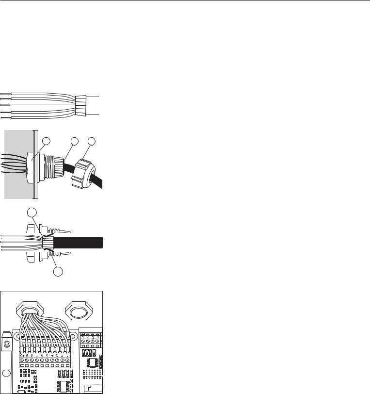
Schnittstellenkabel montieren
§Anschlussbelegung: siehe Abschnitt »Steckerbelegungsplan«.
§Anschlusskabel des Peripheriegerätes mit der Kabelverschraubung mit dem Auswertegerät verbinden.
|
|
|
§ |
Schnittstellenkabel vorbereiten: |
|
|
|
– |
Kabelende ca. 10 cm abisolieren |
|
|
|
– |
Schirmung auf ca. 1cm kürzen und nach hinten über die Isolierung ziehen |
|
|
|
– |
Adern des Verbindungskabels ca. 1cm abisolieren und mit Aderendhülsen versehen |
|
|
|
§ Kabeldurchführung montieren: |
|
1 |
5 |
4 |
!Alle Arbeiten an der Verschraubung vorsichtig durchführen. Einen Drehmomentschlüssel |
|
|
verwenden. Drehmoment dieser Kabelverschraubung: 5 Nm. |
|||
|
|
|
|
|
|
|
|
– |
Blindstopfen an der vorgesehenen Bohrung des Auswertegerätes entfernen |
|
|
|
– |
Beiliegende Kabelverschraubung durch Bohrung stecken und mit Gegenmutter (1) von |
|
|
|
|
innen sichern. |
2 |
– |
Kabel durch die Kabelverschraubung stecken bis die Schirmung (2) Kontakt zu den Klem- |
|
men (3) hat. Druckmutter (4) anziehen bis der Dichteinsatz (5) zwischen Druckmutter und |
|
|
|
|
|
|
Kabel einen kleinen Wulst bildet. |
|
– |
Kontakt der Schirmung mit den Klemmen kontrollieren. |
3 |
§ |
– |
– |
Verbindungskabel anschließen:
Adern entsprechend den Klemmenbelegungsplänen fest an den Klemmen verschrauben. Belegungspläne siehe Seite 28.
§Auswertegerät wieder verschließen. Darauf achten, dass der Dichtring zwischen Gehäuse und Frontplatte richtig aufliegt.
§Nach Beendigung der Montagearbeiten den IP65-Schutz überprüfen. Dazu Druckmanometer verwenden. Weitere Informationen dazu sind beim Sartorius Service zu erfragen.
Schnittstelle COM1 und UniCOM für Betrieb einstellen
Nach Einbau und Konfiguration des Schnittstellenmoduls in das Auswertegerät die Schnittstelle UniCOM mit Hilfe des Bedienmenüs für die vorgesehene Funktion einstellen. Siehe dazu das Kapitel »Voreinstellungen COM1 und UniCOM«. Weitere Erläuterungen dazu enthält das Kapitel »Voreinstellungen« der Midrics-Betriebsanleitung.
24
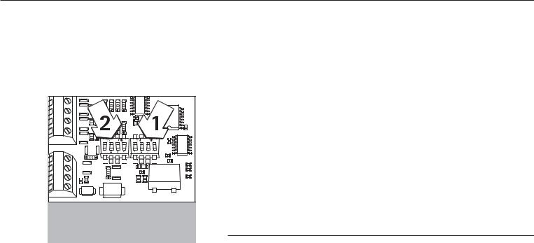
Module konfigurieren:
YDO01M-485, YDO01M-20MA
YDO01M-485 (Optionen A2 und A3)
Merkmale
Das Schnittstellenmodul YDO01M-485 (serielle RS485/RS422-Schnittstelle, galvanisch getrennt1) kann entweder im RS485oder im RS422-Betrieb eingesetzt werden.
Die Konfiguration für die vorgesehene Verwendung erfolgt mit acht Schaltern. Zusätzlich zur Einstellung für den vorgesehenen Betrieb als eine RS485oder RS422-
Schnittstelle müssen je nach Einsatzbereich (Netzwerk oder Punkt-zu-Punkt-Verbindung) die auf der Platine vorhandenen Abschlusswiderstände (120 O) und die Bias-Widerstände aktiviert oder deaktiviert werden.
Die Anordnung der Schalter ist aus der nebenstehenden Strichzeichnung ersichtlich. Bei geschlossenem Schalter 1-4 ist die Schnittstelle für RS422-Betrieb konfiguriert.
Folgende Funktionen stehen zur Verfügung, wenn der jeweilige Schalter geschlossen ist (Stellung: »ON«):
Funktion (ON = geschlossen) |
Schalter |
Abschlusswiderstand, TX-Seite 120O |
1 - 1 |
BIAS-Widerstand, TX-Seite (TXD+, Pull-Up) 680O |
1 - 2 |
BIAS-Widerstand, TX-Seite (TXD–, Pull-Down) 680O |
1 - 3 |
ON: RS422-Betrieb | offen: RS485-Betrieb |
1 - 4 |
Abschlusswiderstand, RX-Seite 120O |
2 - 1 |
BIAS-Widerstand, RX-Seite (RXD+, Pull-Up) 680O |
2 - 2 |
BIAS-Widerstand, RX-Seite (RXD–, Pull-Down) 680O |
2 - 3 |
Ohne Funktion |
2 - 4 |
Hinweis zur Schalterstellung
Immer gleiche Schalterstellung:
–beide Schalter 1–2/1–3 auf ON oder OFF
–beide Schalter 2–2/2–3 auf ON oder OFF
Betrieb als RS485-Schnittstelle (Option A3):
§Der Schalter 1-4 für die Umschaltung zum RS485-Betrieb muss geöffnet sein (Werksvoreinstellung).
§Ggf. Biaswiderstände für den RS485-Betrieb deaktivieren. Dazu die Schalter öffnen (Werkvoreinstellung).
Die Biaswiderstände dürfen in einer Übertragungsstrecke (Netzwerk oder Punkt-zu- Punkt-Verbindung) nur einmal vorkommen, sonst besteht die Gefahr von Übertragungsfehlern. Dazu ggf. Datenblätter oder Schaltungsunterlagen der Gegenstelle oder der Netzwerkknotenpunkte einsehen. Biaswiderstände immer paarweise aktivieren oder deaktivieren.
§Der Abschlusswiderstand (TX-Seite, Schalter 1 – 1) muss aktiviert sein, wenn sich das Gerät an einem der beiden Enden eines RS485-Bussystems befindet oder wenn es mit einem anderen Gerät mit einer Punkt-zu-Punkt-Leitung verbunden ist. In der Gegenstelle muss sich ebenfalls ein Abschlusswiderstand von 120 O befinden. Ggf. Abschlusswiderstand (120 O) für den RS485-Betrieb aktivieren:
Schalter 1 - 1 und 2 - 1 schließen (Stellung »ON«)
Betrieb als RS422-Schnittstelle (Option A2):
§Den Schalter 1 - 4 für die Umschaltung zum RS422-Betrieb schließen (Stellung »ON«)
§Ggf. Biaswiderstände für den RS422-Betrieb deaktivieren. Dazu die Schalter öffnen.
§Den Abschlusswiderstand der RX-Seite aktivieren (Schalter 2 – 1), sofern kein externer Abschlusswiderstand vorhanden ist. TX-Abschlusswiderstände immer deaktivieren (Schalter 1 – 1).
1) Der Schirm des Anschlusskabels ist einseitig mit dem Gehäuse des Auswertegerätes verbunden. Das Auswertegerät ist mit dem Schutzleiter verbunden.
25
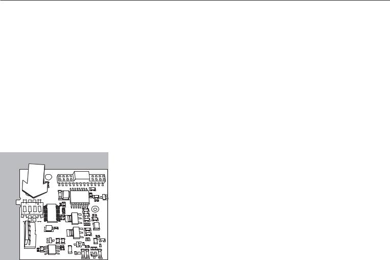
YDA01M-20MA (Option A9)
Merkmale
Das Schnittstellenmodul YDA01M-20MA ist ein Analogausgang. Es kann entweder als Stromschnittstelle (0/4 - 20mA, 0 - 24 mA) oder als Spannungsschnittstelle (0 bis 10 V) betrieben werden. Die Spannungsversorgung erfolgt intern galvanisch getrennt1)).
Das Schnittstellenmodul kann auf einen der vier folgenden Betriebszustände eingestellt werden:
–Spannungsschnittstelle, 0 bis 10 V
–Stromschnittstelle, 0 bis 20 mA
–Stromschnittstelle, 4 bis 20 mA
–Stromschnittstelle, 0 bis 24 mA
Die Konfiguration für die vorgesehene Verwendung erfolgt durch das Schließen und Öffnen von Schaltern. Die Anordnung der Schalter ist aus der nebenstehenden Strichzeichnung ersichtlich.
Die Einstellung auf den jeweiligen Betriebszustand erfolgt durch die Einstellung der Schalter 1 und 2 (Schalter 3 und 4 ohne Funktion):
|
|
|
|
|
|
|
|
|
|
|
|
|
|
|
|
Betriebszustand |
Schalter |
|
|
|
|
|
|
|
|
|
|
|
|
|
|
|
|
||
|
|
|
|
|
|
|
|
|
|
|
|
|
|
|
|
|
|
|
|
|
|
|
|
|
|
|
|
|
|
|
|
|
|
Spannungsschnittstelle, 0 bis 10 V |
SW 1–1: geschlossen = Stellung »ON«, |
|
|
|
|
|
|
|
|
|
|
|
|
|
|
|
|
||
|
|
|
|
|
|
|
|
|
|
|
|
|
|
|
|
|
SW 1–2: offen |
|
|
|
|
|
|
|
|
|
|
|
|
|
|
|
|
|
|
|
|
|
|
|
|
|
|
|
|
|
|
|
|
|
|
Stromschnittstelle, 0 bis 20 mA |
SW 1–1: offen, |
|
|
|
|
|
|
|
|
|
|
|
|
|
|
|
|
|
SW 1–2: geschlossen = Stellung »ON« |
|
|
|
|
|
|
|
|
|
|
|
|
|
|
|
|
Stromschnittstelle, 4 bis 20 mA |
SW 1–1: offen, SW 1–2: offen |
|
|
|
|
|
|
|
|
|
|
|
|
|
|
|
|
||
|
|
|
|
|
|
|
|
|
|
|
|
|
|
|
|
|
(Werkvoreinstellung) |
|
|
|
|
|
|
|
|
|
|
|
|
|
|
|
|
|
|
|
|
|
|
|
|
|
|
|
|
|
|
|
|
|
|
|
|
|
|
|
|
|
|
|
|
|
|
|
|
|
|
|
|
Stromschnittstelle, 0 bis 24 mA |
SW 1–1: geschlossen = Stellung »ON«, |
|
|
|
|
|
|
|
|
|
|
|
|
|
|
|
|
|
SW 1–2: geschlossen = Stellung »ON« |
1) Der Schirm des Anschlusskabels ist einseitig mit dem Gehäuse des Auswertegerätes verbunden. Das Auswertegerät ist mit dem Schutzleiter verbunden.
–Max. Bürde: 390 Ohm
Hinweise
–Der Schirm des Anschlusskabels der Stromschnittstelle ist einseitig mit dem Gehäuse des Auswertegerätes verbunden.
–Das Auswertegerät ist mit dem Schutzleiter verbunden.
–Wird das Auswertegerät mit einem internen oder externen Akku versorgt, ist ein Betrieb der Stromschnittstelle nicht möglich.
§Das Schnittstellenmodul YDA01M-20MA wird direkt auf die Digitalplatine der Midrics Auswertegeräte (MIS..., MW...) aufgesteckt. Siehe dazu das Kapitel »Einbau in das Auswertegerät«.
26
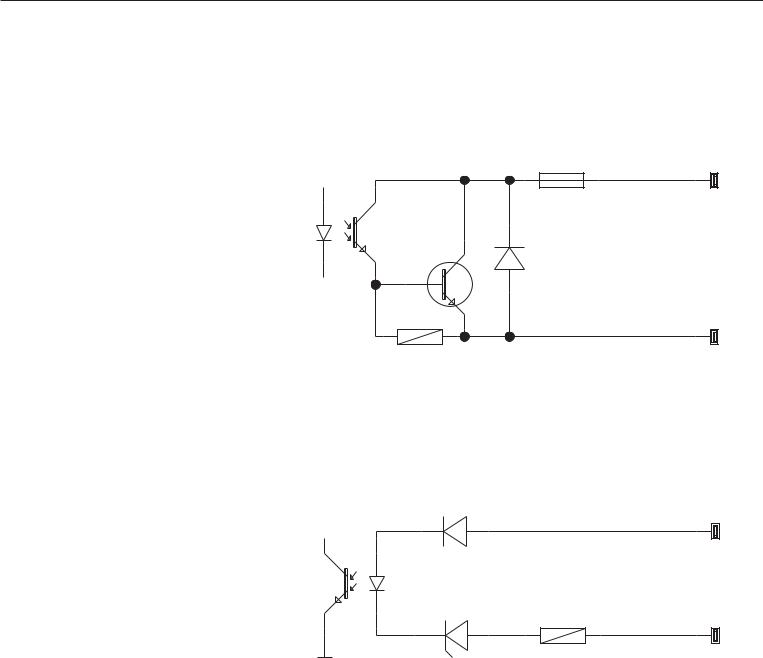
YDO01M-IO, Option A5:
Spezifikationen
|
Digitale Eingänge |
|
– |
Anzahl: |
5 |
– |
Low-Pegel: |
–3 V bis +5 V |
– |
High-Pegel: |
+11 V bis +30 V |
–Max. Stromaufnahme: 2,6 mA bei 15 V
–Schalten der Eingänge durch Anlegen der entsprechenden Spannung.
Digitale Ausgänge |
|
– Anzahl: |
5 |
–Maximaler Stromfluss je Kanal: 100 mA
– Spannungsbereich |
0–30 Vdc |
–Jeder Ausgang wird durch einen Optokoppler gebildet.
YDO01M-EN (Option B9)
Lieferumfang
–Schnittstellenmodul YDO01M-EN
–Betriebsanleitung (dieses Dokument)
–Software-Schnittstellenbeschreibung »Feldbus« für Modbus TCP
Montage
Das Schnittstellenmodul YDO01M-EN (Ethernet-Schnittstelle) wird ohne Konfiguration direkt mit der Digitalplatine der Waage verbunden. Siehe dazu das Kapitel »Einbau in Auswertegerät«. Stecker des Sartorius Ethernet-Kabels YCC02RJ45M7 (Option M38) in die Buchse des Schnittstellenmoduls stecken.
Hinweis:
!Nur Kabel und Stecker gemäß der Ethernet-Spezifikation verwenden (CAT5 oder höher):
Ethernet-Kabel mit Kabelverschraubung Sartorius Bestell-Nr. YCC02RJ45M7 (Option M38)
Schnittstellenmodul nur in folgenden Geräten einsetzbar:
–Indikator MIS1, MIS2 (IP65)
–Komplettwaage MW1, MW2 (IP65)
Beispiel: Prinzipschaltbild
|
|
0.2A |
OUTx_high |
LV1 |
|
|
30V |
|
|
1 |
4 |
|
|
2 3
OUTx_low
LV1
Inputx_high
LV2
4 1
3 |
2 |
Inputx_low |
LV2 |
|
|
|
27
Loading...