


 Loading...
Instrument Manual
Ethernet Transmitter Series PR 5220 PR 5220/00 Ethernet Transmitter
PR 5220/01 Ethernet Transmitter with ProfiBus PR 5220/04 Ethernet Transmitter with DeviceNet
PR 5220/06 Ethernet Transmitter with ProfiNet I/O PR 5220/07 Ethernet Transmitter with EtherNet-IP
Instrument Manual |
9499 050 52201 |
Edition 6 |
08.07.2013 |
for PR 5220 |
Release: 2.10 |
|
|
Sartorius Mechatronics T&H GmbH, Meiendorfer Str. 205, 22145 Hamburg, Germany Tel:+49.40.67960.303 Fax:+49.40.67960.383

Please note
Any information in this document is subject to change without notice and does not represent a commitment on the part of SARTORIUS unless legally prescribed. This product should be operated only by trained and qualified personnel. In correspondence concerning this product the type, name and release number as well as all license numbers in relation to the product have to be quoted.
Bitte beachten
Alle Angaben in diesem Dokument sind - soweit nicht gesetzlich vorgegeben - unverbindlich für SARTORIUS und stehen unter Änderungsvorbehalt. Die Bedienung des Produktes darf nur von geschultem, fachund sachkundigem Personal durchgeführt werden. Bei Schriftwechsel über dieses Produkt bitte Typ, Bezeichnung und Versionsnummer sowie alle mit dem Produkt in Zusammenhang stehenden Lizenznummern angeben.
PR 5220 Instrument Manual |
Table of Contents |
||
|
|
||
Table of Contents |
|
||
1 |
Safety Information...................................................................................................................................................................................... |
7 |
|
1.1 |
General Information.................................................................................................................................................................................... |
7 |
|
1.2 |
Intended Use.................................................................................................................................................................................................. |
7 |
|
1.3 |
Initial Inspection........................................................................................................................................................................................... |
7 |
|
1.4 |
Before Commissioning................................................................................................................................................................................ |
7 |
|
1.4.1 |
Installation ........................................................................................................................................................................................ |
8 |
|
1.4.2 |
Electrostatically Sensitive Components ................................................................................................................................... |
8 |
|
1.4.3 |
Protective Earth............................................................................................................................................................................... |
8 |
|
1.4.4 |
Supply Voltage Connection ......................................................................................................................................................... |
8 |
|
1.4.5 |
Failure and Excessive Stress......................................................................................................................................................... |
9 |
|
1.4.6 |
Fuse...................................................................................................................................................................................................... |
9 |
|
1.4.7 |
EMC-Compliant Installation ........................................................................................................................................................ |
9 |
|
2 |
Ethernet Transmitter Series .................................................................................................................................................................... |
10 |
|
2.1 |
The Transmitter Versions.......................................................................................................................................................................... |
10 |
|
2.1.1 |
PR 5220/00 Version ...................................................................................................................................................................... |
10 |
|
2.1.2 |
PR 5220/01 ProfibBus.................................................................................................................................................................. |
10 |
|
2.1.3 |
PR 5220/04 DeviceNet................................................................................................................................................................. |
10 |
|
2.1.4 |
PR 5220/06 ProfiNet I/O............................................................................................................................................................. |
10 |
|
2.1.5 |
PR 5220/07 EtherNet-IP ............................................................................................................................................................. |
10 |
|
2.2 |
Overview of the Instrument ................................................................................................................................................................... |
11 |
|
2.3 |
Label on the Housing ................................................................................................................................................................................ |
12 |
|
2.4 |
Housing Dimensions.................................................................................................................................................................................. |
12 |
|
2.5 |
Display and Controls ................................................................................................................................................................................. |
13 |
|
2.5.1 |
Status LEDs...................................................................................................................................................................................... |
13 |
|
2.5.2 |
Operation Using the VNC Program ......................................................................................................................................... |
14 |
|
2.6 |
Overview of Connections......................................................................................................................................................................... |
19 |
|
3 |
Installing the Instrument ........................................................................................................................................................................ |
20 |
|
3.1 |
Connections ................................................................................................................................................................................................. |
20 |
|
3.1.1 |
Network Port .................................................................................................................................................................................. |
20 |
|
3.1.2 |
RS-485 Interface ........................................................................................................................................................................... |
21 |
|
3.1.3 |
Analog Output ............................................................................................................................................................................... |
25 |
|
3.1.4 |
Optocoupler Inputs....................................................................................................................................................................... |
26 |
|
3.1.5 |
Optocoupler Outputs ................................................................................................................................................................... |
27 |
|
3.1.6 |
Load Cell Connection................................................................................................................................................................... |
28 |
|
3.1.7 |
Connecting Analog Platforms (CAP...).................................................................................................................................... |
31 |
|
3.1.8 |
Connecting xBPI Platforms (IS...) ............................................................................................................................................. |
32 |
|
3.1.9 |
Connection of Digital Load Cells.............................................................................................................................................. |
32 |
|
3.1.10 |
ProfiBus Interface (PR 5220/01 only)..................................................................................................................................... |
33 |
|
3.1.11 |
DeviceNet Interface (PR 5220/04 only) ................................................................................................................................. |
34 |
|
3.1.12 |
ProfiNet I/O Interface (PR 5220/06 only).............................................................................................................................. |
35 |
|
3.1.13 |
EtherNet-IP Interface (PR 5220/07 only) .............................................................................................................................. |
36 |
|
Sartorius |
EN-3 |
Table of Contents |
PR 5220 Instrument Manual |
|||
|
|
|
|
|
4 |
Commissioning........................................................................................................................................................................................... |
|
37 |
|
4.1 |
Data Backup/Power Failure.................................................................................................................................................................... |
|
37 |
|
4.1.1 |
CAL Switch ..................................................................................................................................................................................... |
|
37 |
|
4.1.2 |
Factory Settings............................................................................................................................................................................ |
|
38 |
|
4.2 Switching on the Instrument ................................................................................................................................................................ |
|
38 |
||
4.3 |
Configuration and Calibration.............................................................................................................................................................. |
|
38 |
|
4.3.1 |
Connecting the Device to the Network and Finding out the IP address ................................................................... |
38 |
||
4.3.2 |
Resetting the Instrument/Activating Network'DHCP' ...................................................................................................... |
|
41 |
|
4.3.3 |
Searching the Instrument in the Network Using 'IndicatorBrowser' .......................................................................... |
44 |
||
4.3.4 |
Operation Using the VNC Program......................................................................................................................................... |
|
45 |
|
4.3.5 |
Operation Using Internet Browser.......................................................................................................................................... |
|
46 |
|
4.3.6 |
INFO Function................................................................................................................................................................................ |
|
48 |
|
4.3.7 |
Setup Function (VNC) ................................................................................................................................................................. |
|
48 |
|
4.3.8 |
Setup Menu.................................................................................................................................................................................... |
|
49 |
|
4.4 Calibration Weighing Point ‚Internal A’............................................................................................................................................. |
|
55 |
||
4.4.1 |
Displaying Calibration Data ...................................................................................................................................................... |
|
55 |
|
4.4.2 |
Selecting the Calibration Mode............................................................................................................................................... |
|
56 |
|
4.4.3 |
Determining the Maximum Capacity (Max) ........................................................................................................................ |
|
57 |
|
4.4.4 |
Determining the Scale Interval................................................................................................................................................ |
|
59 |
|
4.4.5 |
Determining the Dead Load...................................................................................................................................................... |
|
60 |
|
4.4.6 |
Calibration with Weight (by Load) ......................................................................................................................................... |
|
62 |
|
4.4.7 |
Calibration with mV/V Value [by mV/V]................................................................................................................................ |
|
63 |
|
4.4.8 |
Calibration with Load Cell Data (“Smart Calibration“)..................................................................................................... |
|
64 |
|
4.4.9 |
Subsequent Dead Load Correction ......................................................................................................................................... |
|
65 |
|
4.4.10 |
Linearization .................................................................................................................................................................................. |
|
65 |
|
4.4.11 |
Test Value Determination/Display........................................................................................................................................... |
|
66 |
|
4.4.12 |
Finishing/Saving the Calibration............................................................................................................................................. |
|
66 |
|
4.4.13 |
Parameter Input............................................................................................................................................................................ |
|
67 |
|
4.5 Calibrating an xBPI Scale........................................................................................................................................................................ |
|
70 |
||
4.5.1 |
xBPI Set-up for Serial Port........................................................................................................................................................ |
|
70 |
|
4.5.2 |
xBPI Scale Function ..................................................................................................................................................................... |
|
71 |
|
4.5.3 |
xBPI Platform Configuration.................................................................................................................................................... |
|
71 |
|
4.5.4 |
xBPI Scale Parameter .................................................................................................................................................................. |
|
73 |
|
4.5.5 |
xBPI Parameter Tables ................................................................................................................................................................ |
|
74 |
|
4.5.6 |
xBPI Setting Dead Load.............................................................................................................................................................. |
|
77 |
|
4.5.7 |
xBPI Calibration with the User Weight ................................................................................................................................. |
|
78 |
|
4.5.8 |
xBPI Calibration with Automatic Weight Detection......................................................................................................... |
|
79 |
|
4.5.9 |
xBPI Calibration with Default Weight................................................................................................................................... |
|
80 |
|
4.5.10 |
xBPI Calibration with Built-in Weight .................................................................................................................................. |
|
82 |
|
4.6 Calibrating Digital Load Cells Type ‘Pendeo®’.................................................................................................................................. |
|
83 |
||
4.6.1 |
General Information.................................................................................................................................................................... |
|
83 |
|
4.6.2 |
Viewing the Interfaces................................................................................................................................................................ |
|
83 |
|
4.6.3 |
Selecting and Setting up the Interface................................................................................................................................. |
|
83 |
|
4.6.4 |
Selecting the Load Cell Type..................................................................................................................................................... |
|
84 |
|
4.6.5 |
Adjustment Sequence................................................................................................................................................................. |
|
85 |
|
4.6.6 |
Search for Load Cells................................................................................................................................................................... |
|
85 |
|
4.6.7 |
Assigning Load Cells .................................................................................................................................................................... |
|
87 |
|
EN-4 |
Sartorius |
PR 5220 Instrument Manual |
Table of Contents |
||
|
|
|
|
4.6.8 |
Calibrating Load Cells .................................................................................................................................................................. |
88 |
|
4.6.9 |
Corner Correction ......................................................................................................................................................................... |
91 |
|
4.6.10 |
Finishing/Saving the Calibration.............................................................................................................................................. |
92 |
|
4.6.11 |
Parameter Input ............................................................................................................................................................................ |
93 |
|
4.6.12 |
Subsequent Dead Load Correction .......................................................................................................................................... |
95 |
|
4.7 |
Configuring General Parameters........................................................................................................................................................... |
96 |
|
4.7.1 |
Serial Interfaces [Serial ports parameter] ............................................................................................................................. |
96 |
|
4.7.2 |
Operating Parameters.................................................................................................................................................................. |
98 |
|
4.7.3 |
Fieldbus Parameters ..................................................................................................................................................................... |
99 |
|
4.7.4 |
Network Parameters.................................................................................................................................................................. |
101 |
|
4.8 |
Configuring Limit Values ...................................................................................................................................................................... |
102 |
|
4.9 |
Digital Outputs and Inputs .................................................................................................................................................................. |
106 |
|
4.9.1 |
Configuring Digital Outputs................................................................................................................................................... |
106 |
|
4.9.2 |
Configuring Digital Inputs ...................................................................................................................................................... |
108 |
|
4.10 Analog Output ......................................................................................................................................................................................... |
110 |
||
4.10.1 |
Adapting the Analog Output ................................................................................................................................................. |
111 |
|
4.11 Logfiles ....................................................................................................................................................................................................... |
112 |
||
4.12 Saving Configuration Data [Backup of EAROM]........................................................................................................................... |
113 |
||
4.12.1 |
Saving Configuration and Calibration Data...................................................................................................................... |
113 |
|
4.12.2 |
Loading Configuration and Calibration Data into the Device..................................................................................... |
115 |
|
5 |
J-Bus/ModBus Protocol ........................................................................................................................................................................ |
117 |
|
5.1 |
General Description................................................................................................................................................................................ |
117 |
|
5.2 |
ModBus-TCP/-UDP.................................................................................................................................................................................. |
118 |
|
5.3 |
Functions ................................................................................................................................................................................................... |
119 |
|
5.4 |
Error Messages ......................................................................................................................................................................................... |
123 |
|
5.5 |
Word Addresses ....................................................................................................................................................................................... |
124 |
|
6 |
SMA Protocol........................................................................................................................................................................................... |
125 |
|
6.1 |
General ....................................................................................................................................................................................................... |
125 |
|
6.2 |
Description of Used Symbols............................................................................................................................................................... |
125 |
|
6.3 |
SMA Command Set................................................................................................................................................................................. |
126 |
|
6.4 |
SMA Reply Messages.............................................................................................................................................................................. |
129 |
|
6.5 |
Communication Error ............................................................................................................................................................................ |
134 |
|
7 |
Fieldbus Interface ................................................................................................................................................................................... |
134 |
|
7.1 |
Fieldbus Interface Protocol.................................................................................................................................................................. |
134 |
|
7.2 |
Description of the I/O Area (Read / Write Window) .................................................................................................................... |
136 |
|
7.3 |
Special hints for DeviceNet and EtherNet-IP................................................................................................................................. |
140 |
|
7.4 |
Fieldbus Register ..................................................................................................................................................................................... |
141 |
|
8 |
Global SPM Variables............................................................................................................................................................................. |
145 |
|
9 |
Configuration Print-Out....................................................................................................................................................................... |
148 |
|
10 |
Extended Functions................................................................................................................................................................................ |
150 |
|
10.1 Resetting the Instrument to the Factory Settings........................................................................................................................ |
150 |
||
10.2 Updating a new Software with ‚FlashIt’ .......................................................................................................................................... |
151 |
||
Sartorius |
EN-5 |
Table of Contents |
PR 5220 Instrument Manual |
|||
|
|
|
||
11 |
Repairs and Maintenance ..................................................................................................................................................................... |
153 |
||
11.1 |
Solder Work............................................................................................................................................................................................... |
153 |
||
11.2 |
Cleaning ..................................................................................................................................................................................................... |
153 |
||
12 |
Disposal ...................................................................................................................................................................................................... |
|
153 |
|
13 |
Error Messages ......................................................................................................................................................................................... |
154 |
||
13.1 |
Measuring Circuit Error Messages ..................................................................................................................................................... |
154 |
||
13.2 |
Weight Error Status................................................................................................................................................................................ |
155 |
||
13.3 |
Error Messages with xBPI Scales ........................................................................................................................................................ |
155 |
||
13.4 |
Error messages of the Calibration...................................................................................................................................................... |
156 |
||
13.5 |
Show Error Log......................................................................................................................................................................................... |
158 |
||
14 |
Specifications ........................................................................................................................................................................................... |
159 |
||
14.1 |
Instructions for Use of 'Free Software' ............................................................................................................................................ |
159 |
||
14.2 |
General Data ............................................................................................................................................................................................. |
160 |
||
|
14.2.1 |
Power Supply............................................................................................................................................................................... |
160 |
|
14.3 |
Effect of Ambient Conditions ............................................................................................................................................................. |
160 |
||
|
14.3.1 |
Environmental Conditions....................................................................................................................................................... |
160 |
|
|
14.3.2 |
Electromagnetic Compatibility (EMC) ................................................................................................................................. |
160 |
|
|
14.3.3 |
RF Interference Suppression................................................................................................................................................... |
160 |
|
14.4 |
Weighing Electronics ............................................................................................................................................................................. |
161 |
||
|
14.4.1 |
Load Cells ...................................................................................................................................................................................... |
161 |
|
|
14.4.2 |
Principle ........................................................................................................................................................................................ |
161 |
|
|
14.4.3 |
Accuracy and Stability.............................................................................................................................................................. |
161 |
|
|
14.4.4 |
Sensitivity ..................................................................................................................................................................................... |
161 |
|
14.5 |
Mechanical Data...................................................................................................................................................................................... |
162 |
||
|
14.5.1 |
Construction ................................................................................................................................................................................ |
162 |
|
|
14.5.2 |
Dimensions ................................................................................................................................................................................... |
162 |
|
|
14.5.3 |
Weight ........................................................................................................................................................................................... |
162 |
|
14.6 |
Use in Legal-for-Trade Mode .............................................................................................................................................................. |
162 |
||
|
14.6.1 |
Documentation for Verification on the Enclosed CD ..................................................................................................... |
162 |
|
|
14.6.2 |
Additional Instructions............................................................................................................................................................. |
162 |
|
15 |
Index............................................................................................................................................................................................................ |
|
163 |
|
16 |
Appendix |
.................................................................................................................................................................................................... |
166 |
|
16.1 |
Pin Assignment for Interface RS-485............................................................................................................................................... |
166 |
||
16.2 |
Network Settings under Windows XP............................................................................................................................................... |
167 |
||
16.3 |
Network Settings under Windows 7 ................................................................................................................................................. |
168 |
||
EN-6 |
Sartorius |

PR 5220 Instrument Manual |
Safety Information |
|
|
1 Safety Information
1.1General Information
The instrument was in perfect condition with regard to safety features when it left the factory. To maintain this condition and to ensure safe operation, the operator must follow the instructions and observe the warnings in this manual.
1.2Intended Use
The instrument is intended for use as an indicator for weighing functions. Product operation, commissioning and maintenance must be performed by trained and qualified personnel who are aware of and able to deal with the related hazards and take suitable measures for self-protection.
The instrument reflects the state of the art. The manufacturer does not accept any liability for damage caused by other system components or due to incorrect use of the product.
1.3Initial Inspection
Check the content of the consignment for completeness and inspect it visually for signs of damage that may have occurred during transport. If there are grounds for rejection of the goods, a claim must be filed with the carrier immediately and the Sartorius sales or service organization must be notified.
1.4Before Commissioning
Visual inspection:
Before commissioning and after and storage or transport, inspect the instrument visually for signs of mechanical damage.
Sartorius |
EN-7 |
Safety Information |
PR 5220 Instrument Manual |
|
|
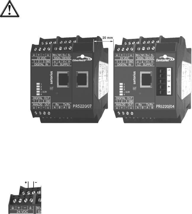
1.4.1Installation
The instrument is designed for mounting on standard rails (35 mm, acc. to DIN 46277).
Caution!
Excessive heat may reduce the instrument lifetime!
When mounting on the rail, make sure that the distance from other instruments left and right of the module is at least 20 mm.
1.4.2Electrostatically Sensitive Components
This instrument contains electrostatically sensitive components. For this reason, an equipotential bonding conductor must be connected when working on the open instrument (antistatic protection).
1.4.3Protective Earth
Connection to protective earth must be performed via the mounting rail.
1.4.4Supply Voltage Connection
The supply voltage is 24V DC +10% / -15%.
Max. power consumption of
-PR 5220/00: 6.5 W
-PR 5220/01: 8.5 W
-PR 5220/04: 8.5 W
-PR 5220/06: 8.5 W
-PR 5220/07: 8.5 W
For connection to 230/115 V AC, an external power supply (e.g. Sartorius PR 1624/00 or Phoenix Mini Power) is required.
EN-8 |
Sartorius |
PR 5220 Instrument Manual |
Safety Information |
|
|
1.4.5Failure and Excessive Stress
If there is any reason to assume that safe operation of the instrument is no longer ensured, shut it down and make sure it cannot be used. Safe operation is no longer ensured if any of the following is true:
-The instrument is physically damaged
-The instrument does not function
-The instrument has been subjected to stresses beyond the tolerance limits (e.g., during storage or transport).
1.4.6Fuse
This instrument does not have a replaceable fuse. The load cell supply voltage is protected against short circuit. In case of failure of the load cell supply voltage, disconnect the instrument from the supply voltage, determine the cause and take remedial measures. Subsequently, the supply voltage can be switched on again.
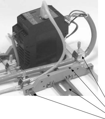
1.4.7EMC-Compliant Installation
- Use only screened data cables.
- Connect screens on both ends with ground. - Keep unscreened cable ends short.
- Connect screen rail to cabinet / housing with low impedance.
- Use metal or metallized connector housings.
- Establish equipotential bonding between instruments / system modules (Mandatory for Ex-applications).
- Use standard reference potential.
- Connect mounting rail to protective earth.
- Install measure and data cables separately from power cables.
Screen clamp (e.g. Phoenix SK8-D)
Rail connection (e.g. Phoenix AB-SK 65D)
Mounting rail (35 mm)
Screen rail (e.g. Phoenix NLS-CU 3/10)
Sartorius |
EN-9 |

Ethernet Transmitter Series |
PR 5220 Instrument Manual |
|
|
2 Ethernet Transmitter Series
2.1The Transmitter Versions
Three PR 5220 series transmitter versions are available; subsequent extension of the version is not possible. The version is determined unambiguously by the type number. The front foils are adapted to the version.
PR 5220/00 |
PR 5220/01 |
PR 5220/04 |
PR 5220/06 |
PR 5220/07 |
2.1.1PR 5220/00 Version
This version has digital inputs and outputs as well as an analog output and a LAN adaptor for configuration and operation of the instrument. Connecting e.g. a remote indicator is possible via the serial output.
2.1.2PR 5220/01 ProfibBus
In addition to PR 5220/00, the instrument is provided with a ProfiBus port.
2.1.3PR 5220/04 DeviceNet
In addition to PR 5220/00, the instrument is provided with a DeviceNet port.
2.1.4PR 5220/06 ProfiNet I/O
In addition to PR 5220/00, the instrument is provided with a ProfiNet I/O port.
2.1.5PR 5220/07 EtherNet-IP
In addition to PR 5220/00, the instrument is provided with a EtherNet-IP port.
EN-10 |
Sartorius |
PR 5220 Instrument Manual |
Ethernet Transmitter Series |
|
|
2.2Overview of the Instrument
-
-
-
-
-
-
-
-
-
-
-
-
Accuracy 10,000 e @ 6 samples/sec Internal resolution: 7.5 million counts Linearity: < 0.002%
Sampling rate: 6 ... 100/sec selectable Digital filter with selectable characteristic Electrically isolated interfaces
3 programmable pairs of limit values
24 VDC supply voltage connection Connection using plug-in terminal blocks Socket for LAN adaptor
The instrument is provided for snap-on mounting on a standard rail.
5 status LEDs für supply voltage, communication, error detection
Calibration and configuration of the instrument are menu guided using a PC.
-Calibration with weight, using the mV/V method or with load cell data (“smart calibration”)
-0/4 ... 20 mA analog output, configurable for gross/net weight
-Analog value via fieldbus
-3 digital input channels, electrically isolated
-3 digital output channels, electrically isolated
Communication protocols
For the internal RS-485:
-Remote display protocol
-SMA protocol
-xBPI protocol
For the internal LAN:
-ModBus-TCP
-Ethernet-TCP/IP
-OPC
Fieldbus slave:
-PR 5220/01 ProfiBus-DP
-PR 5220/04 DeviceNet
-PR 5220/06 ProfiNet I/O
-PR 5220/07 EtherNet-IP
Sartorius |
EN-11 |

Ethernet Transmitter Series |
PR 5220 Instrument Manual |
|
|
2.3Label on the Housing
A label with the wiring diagram is located on one side of the instrument:
2.4Housing Dimensions
PR 5220/00 PR 5220/01, -/04, -/06, -/07
EN-12 |
Sartorius |
PR 5220 Instrument Manual |
Ethernet Transmitter Series |
|
|
2.5Display and Controls
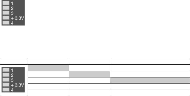
2.5.1Status LEDs
The instrument has 5 green LEDs for display of the operating or error status.
2.5.1.1Power Supply, Bus Connection
|
Power on |
Bus |
Bus connection not provided |
|
|
|
|
|
|
|
|
|
|
|
|
|
|
|
|
|
lit |
|
|
|
|
lit * |
blinks 1 Hz |
|
|
|
|
*The LED for the bus activity (PR 5220/01 a. PR 5220/04) is lit as soon as there is a connection. It continues being lit, also when there is no communication, or when the physical connection is cut.
2.5.1.2Weight Status Indicator
Standstill |
Center zero |
Below zero or above max. capacity |
lit
lit
lit
Note: The weight error status sees in Chapter 13.2.
Sartorius |
EN-13 |
Ethernet Transmitter Series |
PR 5220 Instrument Manual |
|
|
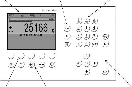
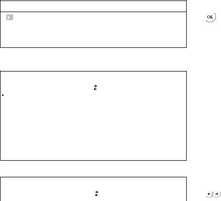
2.5.2Operation Using the VNC Program
2.5.2.1Operator Interface
Display |
Function keys |
Alphanumeric keys |
Softkeys |
Indicator keys |
Navigation/menu keys |
EN-14 |
Sartorius |
PR 5220 Instrument Manual |
Ethernet Transmitter Series |
|
|
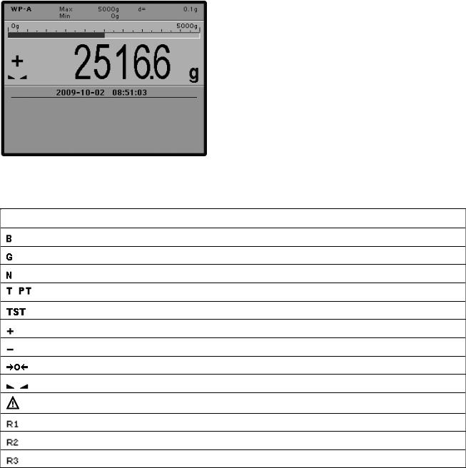
The display shows weight values of up to 7 digits with decimal point and plus or minus sign.
Available mass units are mg, g, kg, t, lb or oz.
lb and oz units are not permitted for use in legal metrology in the EU and EEC.
The weight readout shows the current weight on a bar graph that indicates proportion of the maximum capacity (Max), with 0 on the left and 100 % on the right.
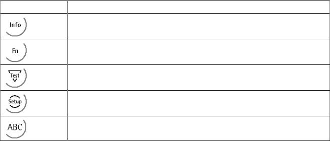
2.5.2.2Status Symbols
The following status symbols can be shown:
Symbol Description
Gross weight (Brutto)
Gross weight in NTEP or NSC mode
Net weight (Net = gross – Tare)
, |
Tare weight, fixtare |
The display shows the test value without mass unit
Positive value
Negative value
The weight value is within ±¼ d of zero
The weight value is stable.
Value not permissible in legal metrology (e.g., 10-fold resolution).
Range 1
Range 2
Range 3
Sartorius |
EN-15 |

Ethernet Transmitter Series |
PR 5220 Instrument Manual |
|
|
2.5.2.3Keys
The following tables show the basic meanings of symbols on the operator interface.
Indicator key |
Description |
|
|
|
Display gross weight |
|
|
|
Display tare weight |
|
|
|
Taring; the current gross weight is stored in the tare memory, provided that: |
|
- weight value is stable. |
|
- instrument is not in error status (function dependent on configuration). |
|
|
|
Sets gross weight to zero, provided that (function dependent on configuration): |
|
- weight value is stable. |
|
- weight is within zero setting range |
|
|
|
Start printing. |
|
|
|
|
Navigation key |
Description |
|
|
|
Cursor moves to the right. |
|
Selection |
|
|
|
Cursor moves to the left. |
|
Selection |
|
|
|
Scroll up in the menu. |
|
|
|
Scroll down in the menu. |
|
|
|
|
Menu key |
Description |
|
|
|
Softkey: select function |
|
|
|
Backspace/delete |
|
|
|
Exit from current menu; continue operation on next higher level. |
|
|
|
Enter/confirm |
|
|
EN-16 |
Sartorius |
PR 5220 Instrument Manual |
Ethernet Transmitter Series |
|
|
Function key
Description
Information on version number, fitted hardware,10-fold resolution
Without function
Test
Open the setup menu
Toggle to alphabetic input mode.
During configuration, you can switch between the mass units by pressing this key.
2.5.2.4Operation Using Softkeys
The functions of the five softkeys  below the graphic display are indicated in the bottommost text line of the display. Softkey functions shown in gray are not available on the active menu level, or not with the active access privileges.
When operating steps involving softkeys are described in this manual, the softkey labels are shown in square brackets, rather than in graphics of the softkeys.
|
|
|
|
|
Setup |
Config |
Calib |
Param |
|
|
|
|
|
|
Sartorius |
EN-17 |
Ethernet Transmitter Series |
PR 5220 Instrument Manual |
|
|
2.5.2.5Selection Using the Navigation Keys
Press  to scroll down, or
  to scroll up in a menu.
Press  to select a menu item. To select the desired setting for the selected menu item, press
  .
.
Press  to exit the menu and continue the operation on the next higher level.
An arrow  in front of a menu item indicates that there are menu sublevels. The menu item selected by pressing
  is shown inversely.
Info
Show version |
Press |
to select an item. |
|
|
|
 Show status
 Show HW-slots
If the list of menu items is long, a vertical bar graph on the left (black and gray) shows which part of the list is displayed.
Weighingpoint/WP A/Calibration
|
Measuretime |
320 ms |
|
|
|
|
|
|
Digital filter |
off |
|
|
Test mode |
absolute |
|
|
|||
|
W & M |
none |
|
|
Standstill time |
0.50 |
s |
|
Standstill range |
1.00 |
d |
|
|
|
|
Availability of additional settings options selectable with  is indicated by preceding double arrows
  .
.
Weighingpoint/WP A/Calibration
|
|
|
|
Measuretime |
640 ms Press |
to select the measuring time. |
|
|
|
|
|
EN-18 |
Sartorius |
PR 5220 Instrument Manual |
Ethernet Transmitter Series |
|
|
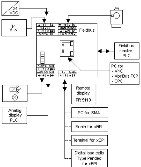
2.6Overview of Connections
Sartorius |
EN-19 |
Installing the Instrument |
PR 5220 Instrument Manual |
|
|
3 Installing the Instrument
•Before starting work, please read Chapter 1 and follow all instructions. Further procedures:
•Check the consignment: unpack the components specific to the application.
•Safety check: inspect all components for damage.
•Make sure the on-site installation is correct and complete including cables, e.g. power cable fuse protection, load cells, cable junction box, data cable, console/cabinet, etc.
•Follow the instructions for installation of the unit relating to application, safety, ventilation, sealing and environmental influences.
•Connect the cable from cable junction box or platform/load cell.
•If applicable: connect other data cables, network cables, etc.
•Connect the instrument to the supply voltage.
•Check the installation.
3.1Connections
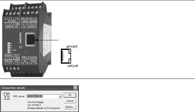
3.1.1Network Port
The network port is built in as standard equipment. The port contains powerful TCP/IP connection circuitry with transfer rates of 10 or 100 Mbit/sec. The LEDs on the connector (RJ-45) indicate whether the port is functioning.
Transfer rate |
10 Mbit/sec, 100 Mbit/sec, |
|
full/half duplex, auto-detection |
Connection method |
Point to point |
|
|
Cable |
CAT 5 patch cable, shielded twisted pair |
|
|
Cable impedance |
150 ¥ |
Electrical isolation |
yes |
Connection |
RJ-45 socket on top of housing |
Remote operation of the instrument from the notebook/PC is possible; install VNC program version 3.3.7* on the notebook/PC. For setting the network address, see
Chapter 4.3.3.
*Sartorius guarantees the functionality only if this version is used!
EN-20 |
Sartorius |
PR 5220 Instrument Manual |
Installing the Instrument |
|
|
3.1.2RS-485 Interface
The interface is intended for connecting a remote display, a PC for data transmission using the SMA protocol or scale/terminal/digital load cells, type Pendeo for data transmission using the xBPI protocol.
|
|
Connection method |
4-pin plug-in terminal block |
|
|
|
|
|
|
Number of channels/type |
1 RS-485, full/half duplex |
|
|
Transfer rate (Bits/s) |
300, 600, 1200, 2400, 4800, <9600>, 19200 |
|
|
|
|
|
|
Bits/stop bits |
<8/1> or 7/1 |
|
|
|
|
|
|
Parity |
<even>, <odd>, <none> |
|
|
|
|
|
|
Signals |
RxA (R-), RxB (R+), TxA, TxB |
|
|
Electrical isolation |
yes |
|
|
Cable length |
max. 1000 m |
|
|
Cable type |
Shielded twisted pair (e.g. LifYCY 2x2x0.20) |
|
|
|
|
< > = default settings (factory settings)... |
|
||
Sartorius |
EN-21 |
Installing the Instrument |
PR 5220 Instrument Manual |
|
|
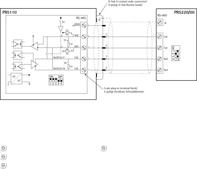
3.1.2.1Connecting of a PR 5110 Remote Display
Four-wire transmission, point to point, full duplex (simultaneous sending and receiving possible) with PR 5110 remote display.
Note: When replacing PR 1627/PR 1628 with PR 5110, note that the pin assignment must be attended, see Chapter 16.1.
Description see instrument manual PR 5110.
Switch settings |
Switch settings |
||
ON: |
S1, S2, S3 |
ON: |
S2 |
OFF: |
S4, S5 |
OFF: |
S1, S3, |
|
S4 is not relevant! |
|
Configuration PR 5110 |
Configuration PR 5220/00 |
|
- - – |
- [Serial ports parameter]-[Remote display]- |
|
- – - |
[Builtin RS485] |
|
[Param]: [Mode]-[single transmitter] |
||
|
||
- – - |
|
The following operations are possible from the connected remote display:
-Switch over to another weighing point
-Indicate current value type
-Set tare
-Reset tare
-Set zero
-Start Print
EN-22 |
Sartorius |
PR 5220 Instrument Manual |
Installing the Instrument |
|
|
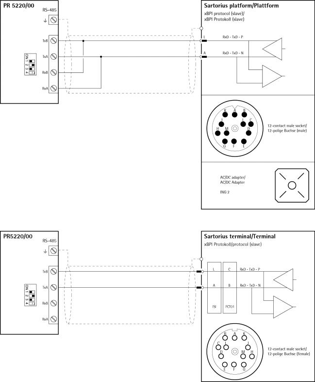
3.1.2.2Connection of a xBPI Platform
Switch settings
ON: S1, S3
OFF: S2
S4 is not relevant!
Configuration PR 5220
 -[Serial ports parameter]-[xBPI-Port]-[Builtin RS485]
3.1.2.3Connection of a xBPI terminal
Switch settings
ON: S1, S3
OFF: S2
S4 is not relevant!
Configuration PR 5220
 -[Serial ports parameter]-[xBPI-Port]-[ Builtin RS485]
Sartorius |
EN-23 |
Installing the Instrument |
PR 5220 Instrument Manual |
|
|
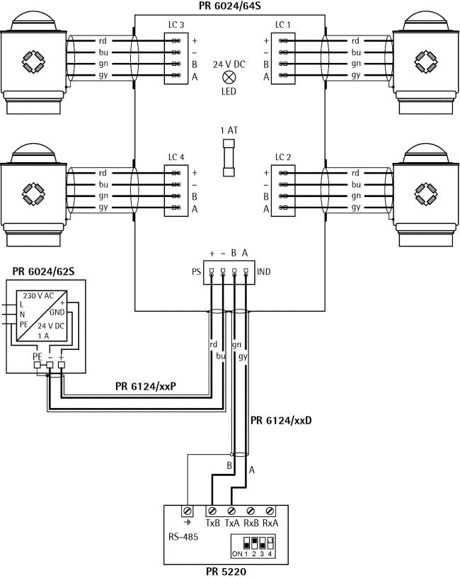
3.1.2.4Connecting 4 Digital Load Cells Type ‚Pendeo®‘
Switch settings
ON: S1, S3
OFF: S2
S4 is not relevant!
Configuration PR 5220
 -[Serial ports parameter]-[xBPI-Port]-[ Builtin RS485]
EN-24 |
Sartorius |
|
PR 5220 Instrument Manual |
Installing the Instrument |
||
|
|
|
|
|
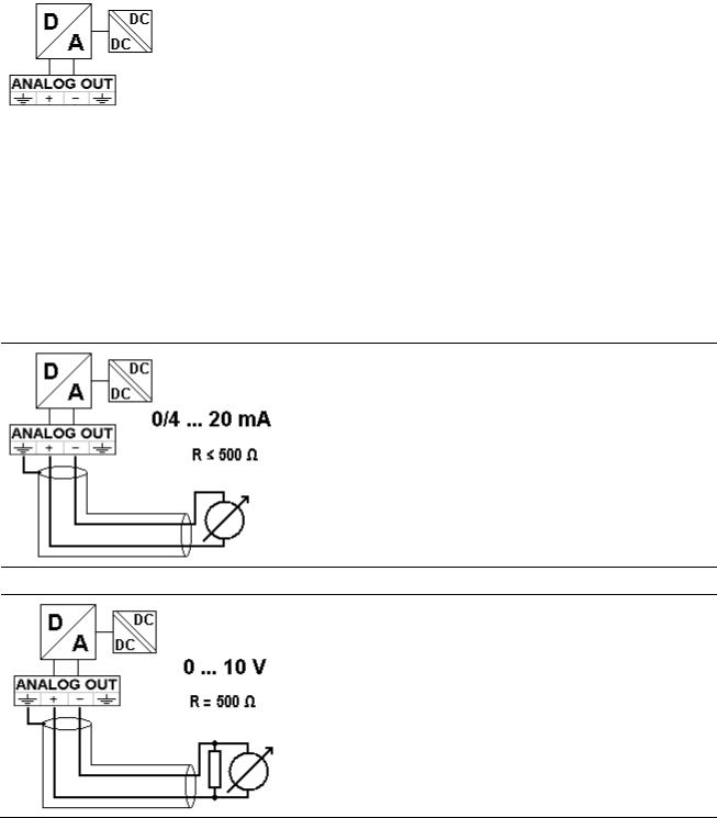
3.1.3 |
Analog Output |
|
||
|
|
|
|
|
|
|
|
Connection method |
4-pin plug-in terminal block |
|
|
|
Number of outputs |
1 current output, |
|
|
|
|
output voltage via external resistor |
|
|
|
Output |
Gross, net weight or via ProfiBus |
|
|
|
Range |
0/4 ... 20mA, configurable |
|
|
|
Resolution |
e.g. 0 - 20 mA in max. 40,000 counts |
|
|
|
|
|
|
|
|
Linearity error |
@ 0 - 20mA: <0,05 % |
|
|
|
|
@ 4 - 20 mA: <0,025 % |
|
|
|
|
|
|
|
|
Temperature effect |
<100 ppm/K |
|
|
|
Load |
0 ... max. 500 ¥ |
|
|
|
Protected against short |
yes |
|
|
|
circuit |
|
|
|
|
Electrical isolation |
yes |
|
|
|
|
|
|
|
|
Cable length (shielded) |
150 m (current output) |
|
|
|
|
|
0/4…20mA
Analog signal, current output
The current is supplied directly via the terminals.
0…10V
Analog signal, voltage output
The voltage level corresponds to the voltage drop across the 500 ¥
(10 ppm/K) resistor.
Sartorius |
EN-25 |
Installing the Instrument |
PR 5220 Instrument Manual |
|
|
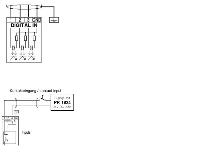
3.1.4Optocoupler Inputs
The 3 optocoupler inputs have one common potential (GND) for the input group that is separated from the common potential of the output group.
|
Connection method |
4-pin plug-in terminal block |
|
|
|
|
Cable |
Shielded, max. 50 m |
|
Number of outputs |
3 |
|
Input signal |
External supply required |
|
|
10…28 V DC for 'high' level |
|
|
0…5 V DC for 'low' level |
|
|
|
|
Input voltage |
Max. 28 V DC |
|
Input current |
<11 mA @ 24 V DC |
|
|
<5 mA @ 12 V DC |
|
Electrical isolation |
Yes; a common minus potential for the group |
|
|
of 3 inputs |
Example: contact input connection
When a voltage ≥10 V DC is applied to the terminals (in the example:1-GND), input 1 is active (true).
EN-26 |
Sartorius |
PR 5220 Instrument Manual |
Installing the Instrument |
|
|
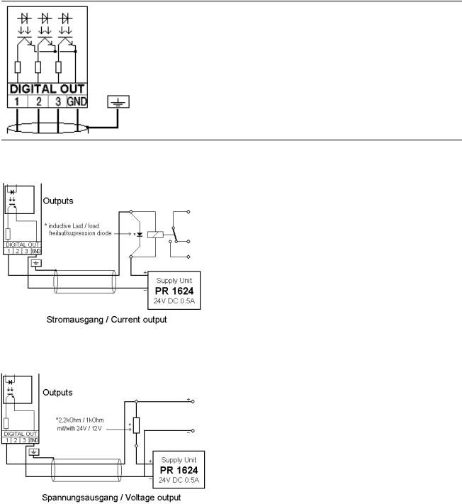
3.1.5Optocoupler Outputs
The 3 optocoupler outputs have one common potential (GND) for the output group that is separated from the common potential of the input group.
Connection method |
4-pin plug-in terminal block |
|
|
Cable |
Shielded, max. 50 m |
Number of outputs |
3 |
Output signal |
External supply required |
Output current |
Max. 30 mA |
|
|
Output voltage |
Max. switching voltage: 28 VDC |
|
|
Electrical isolation |
Yes; a common minus potential for the group |
|
of 3 outputs |
Example: relay control connection
When output 1 is active (true), the relay switches. For protection of the output circuit, relays with free-wheel diode must be provided.
Example: voltage output connection
When output 1 is active (true), the output voltage changes from 24/12 V DC into <3 V DC.
A load resistance of 2.2/1 k¥ must be provided.
Sartorius |
EN-27 |
Installing the Instrument |
PR 5220 Instrument Manual |
|
|
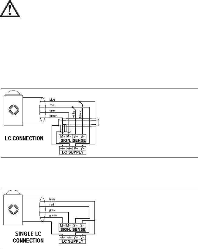
3.1.6Load Cell Connection
The cable colors shown in this chapter are applicable to the Sartorius PR 62XX series load cells.
Before connecting other types, carefully follow the information related to the assignment of load cell/platform cable colors.
•The distance between the measuring cables and the power cables should be at least 1 m.
•The measuring cables should be laid in separate cable conduits or steel pipes connected to earth potential.
•Power cables should be crossed at right angles.
Load cell supply circuit
The load cell supply voltage is fixed to 12 V DC and protected against short circuit.
Load resistance of load cells ≥75 ¥, e.g. 8 load cells of 650 ¥ each.
3.1.6.1 Connection Using 6-Wire Technology
See also label on the housing outside (Chapter 2.3) and manual of the junction box.
Terminal |
Description |
|
|
SIGN. M+ |
+ signal/LC output |
SIGN. M- |
- signal/LC output |
SENSE S+ |
+ sense |
SENSE S- |
- sense |
LC SUPPLY V+ |
+ supply/excitation |
LC SUPPLY V- |
- supply/excitation |
3.1.6.2Connection of a Load Cell in 4-Wire Technology
Note that links between SENSE S+ and LC SUPPLY V+ and between SENSE S- and LC SUPPLY V- directly at the transmitter must be provided.
Terminal |
Description |
|
|
SIGN. M+ |
+ signal/LC output |
SIGN. M- |
- signal/LC output |
SENSE S+ |
+ sense |
SENSE S- |
- sense |
LC SUPPLY V+ |
+ supply/excitation |
LC SUPPLY V- |
- supply/excitation |
3.1.6.3Connecting PR 6221 Load Cells
See installation manual PR 6221 and PR 6021/08, -/68.
EN-28 |
Sartorius |

PR 5220 Instrument Manual |
Installing the Instrument |
|
|
Testing the Measuring Circuit
A simple test with the load cells connected can be carried out with a multimeter (not with external supply or intrinsically safe load cell interface):
Supply voltage
12 V ±0,8 V
(symmetrical to housing GND)
Sense voltage
12 V ±0,8 V
(symmetrical to housing GND)
Measuring voltage
0 - 12 mV @ WZ mit 1,0 mV/V
0 - 24 mV @ WZ mit 2,0 mV/V
Measuring voltage
0 V ±0,5 V
Sartorius |
EN-29 |
Installing the Instrument |
PR 5220 Instrument Manual |
|
|
3.1.6.4External Load Cell Supply
The internal load cell supply voltage of PR 5220 (V+, V-) is not connected.
The common line of the symmetrical external supply must be connected to the same terminal of PR 5220 as the shield of the load cell/extension cable.
Specification of external supply: ±6 V DC +5 %, -30 %; max ripple. 50 mVpp; max. asymmetry ±3 %.
An external supply voltage smaller than 8 V DC (±4 V DC) must be set under  -[Weighingpoint]-[WP A]- [Calibration]-[Param]-[External supply].
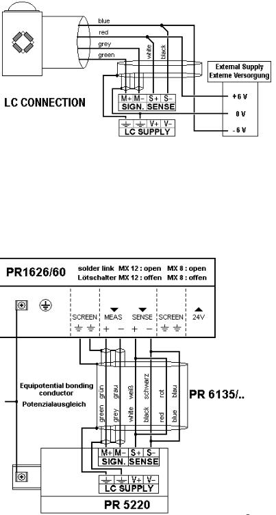
3.1.6.5Connection via Intrinsically Safe Interface PR 1626/60
Connect the instrument to PR 1626/60 as described below. For additional connections, refer to the PR 1626/60 instrument manual. The internal load cell supply voltage of PR 5220 (V+, V-) is not connected.
Note:
If MX8 is closed in PR 1626/60, [below 8 V DC] must be set under
 -[Weighingpoint]-[WP A]-[Calibration]- [Param]- [External supply].
EN-30 |
Sartorius |
Loading...