


 Loading...
320IS Plus
Intrinsically Safe Digital Weight Indicator
Version 2.4
Installation Manual
PN 85353 Rev D

|
Contents |
1.0 Introduction |
.................................................................................................................................. 1 |
Safety ....................................................................................................................................................... |
1 |
1.1 Overview . . . . . . . . . . . . . . . . . . . . . . . . . . . . . . . . . . . . . . . . . . . . . . . . . . . . . . . . . . . . . . . . . . . . . . 2 1.2 Factory Mutual Approval. . . . . . . . . . . . . . . . . . . . . . . . . . . . . . . . . . . . . . . . . . . . . . . . . . . . . . . . . . . 2 1.3 Operating Modes . . . . . . . . . . . . . . . . . . . . . . . . . . . . . . . . . . . . . . . . . . . . . . . . . . . . . . . . . . . . . . . . 2 1.4 Front Panel Keypad . . . . . . . . . . . . . . . . . . . . . . . . . . . . . . . . . . . . . . . . . . . . . . . . . . . . . . . . . . . . . . 3 1.5 Front Panel Configuration . . . . . . . . . . . . . . . . . . . . . . . . . . . . . . . . . . . . . . . . . . . . . . . . . . . . . . . . . . 5 1.6 LED Annunciators. . . . . . . . . . . . . . . . . . . . . . . . . . . . . . . . . . . . . . . . . . . . . . . . . . . . . . . . . . . . . . . . 6 1.7 Indicator Operations . . . . . . . . . . . . . . . . . . . . . . . . . . . . . . . . . . . . . . . . . . . . . . . . . . . . . . . . . . . . . . 7
1.7.1 Toggle Gross/Net Mode . . . . . . . . . . . . . . . . . . . . . . . . . . . . . . . . . . . . . . . . . . . . . . . . . . . . . . . . . . . . 7 1.7.2 Toggle Units . . . . . . . . . . . . . . . . . . . . . . . . . . . . . . . . . . . . . . . . . . . . . . . . . . . . . . . . . . . . . . . . . . . . . 7 1.7.3 Zero Scale. . . . . . . . . . . . . . . . . . . . . . . . . . . . . . . . . . . . . . . . . . . . . . . . . . . . . . . . . . . . . . . . . . . . . . . 7 1.7.4 Acquire Tare . . . . . . . . . . . . . . . . . . . . . . . . . . . . . . . . . . . . . . . . . . . . . . . . . . . . . . . . . . . . . . . . . . . . . 7 1.7.5 Remove Stored Tare Value . . . . . . . . . . . . . . . . . . . . . . . . . . . . . . . . . . . . . . . . . . . . . . . . . . . . . . . . . . 7 1.7.6 Alternate Method to Remove Tare. . . . . . . . . . . . . . . . . . . . . . . . . . . . . . . . . . . . . . . . . . . . . . . . . . . . . 7 1.7.7 Acquire Parts Sample . . . . . . . . . . . . . . . . . . . . . . . . . . . . . . . . . . . . . . . . . . . . . . . . . . . . . . . . . . . . . . 7 1.7.8 Display Part Weight . . . . . . . . . . . . . . . . . . . . . . . . . . . . . . . . . . . . . . . . . . . . . . . . . . . . . . . . . . . . . . . . 8 1.7.9 Display or Change Time/Date . . . . . . . . . . . . . . . . . . . . . . . . . . . . . . . . . . . . . . . . . . . . . . . . . . . . . . . . 8 1.7.10 Print Ticket . . . . . . . . . . . . . . . . . . . . . . . . . . . . . . . . . . . . . . . . . . . . . . . . . . . . . . . . . . . . . . . . . . . . . . 8 1.7.11 Display or Change Setpoint Value . . . . . . . . . . . . . . . . . . . . . . . . . . . . . . . . . . . . . . . . . . . . . . . . . . . . . 8 1.7.12 Turn Setpoint On or Off . . . . . . . . . . . . . . . . . . . . . . . . . . . . . . . . . . . . . . . . . . . . . . . . . . . . . . . . . . . . . 8 1.7.13 Display or Clear Accumulator . . . . . . . . . . . . . . . . . . . . . . . . . . . . . . . . . . . . . . . . . . . . . . . . . . . . . . . . 8
2.0 |
Installation ................................................................................................................................... |
9 |
|
|
2.1 |
Unpacking and Assembly . . . . . . . . . . . . . . . . . . . . . . . . . . . . . . . . . . . . . . . . . . . . . . . . . . . . . . . . . . |
9 |
|
2.2 |
Enclosure Disassembly. . . . . . . . . . . . . . . . . . . . . . . . . . . . . . . . . . . . . . . . . . . . . . . . . . . . . . . . . . . . |
9 |
|
2.3 |
Hazardous Area Installation of the 320IS Plus. . . . . . . . . . . . . . . . . . . . . . . . . . . . . . . . . . . . . . . . . . |
10 |
2.3.1 Power Supply to Indicator . . . . . . . . . . . . . . . . . . . . . . . . . . . . . . . . . . . . . . . . . . . . . . . . . . . . . . . . . . 10 2.3.2 AC Power Wiring. . . . . . . . . . . . . . . . . . . . . . . . . . . . . . . . . . . . . . . . . . . . . . . . . . . . . . . . . . . . . . . . . 11 2.3.3 Battery Option. . . . . . . . . . . . . . . . . . . . . . . . . . . . . . . . . . . . . . . . . . . . . . . . . . . . . . . . . . . . . . . . . . . 11
2.4 Cable Connections and Installation. . . . . . . . . . . . . . . . . . . . . . . . . . . . . . . . . . . . . . . . . . . . . . . . . . 11
2.4.1 Braided Power Cable Connection with Ferrite Core . . . . . . . . . . . . . . . . . . . . . . . . . . . . . . . . . . . . . . . 12 2.4.2 Braided Power Cable Connection Without Ferrite Core . . . . . . . . . . . . . . . . . . . . . . . . . . . . . . . . . . . . 13 2.4.3 Braided Load Cell Cable Connection . . . . . . . . . . . . . . . . . . . . . . . . . . . . . . . . . . . . . . . . . . . . . . . . . 13 2.4.4 Foil Load Cell Cable Connection . . . . . . . . . . . . . . . . . . . . . . . . . . . . . . . . . . . . . . . . . . . . . . . . . . . . . 14 2.4.5 Load Cells . . . . . . . . . . . . . . . . . . . . . . . . . . . . . . . . . . . . . . . . . . . . . . . . . . . . . . . . . . . . . . . . . . . . . . 15
|
2.5 |
Fiber Optics Installation . . . . . . . . . . . . . . . . . . . . . . . . . . . . . . . . . . . . . . . . . . . . . . . . . . . . . . . . . . |
16 |
|
|
|
2.5.1 |
Assembling Fiber Optics Connectors. . . . . . . . . . . . . . . . . . . . . . . . . . . . . . . . . . . . . . . . . . . . . . . . . . |
16 |
|
2.6 |
Enclosure Reassembly . . . . . . . . . . . . . . . . . . . . . . . . . . . . . . . . . . . . . . . . . . . . . . . . . . . . . . . . . . . |
16 |
|
|
2.7 |
Control Drawings . . . . . . . . . . . . . . . . . . . . . . . . . . . . . . . . . . . . . . . . . . . . . . . . . . . . . . . . . . . . . . . |
19 |
|
3.0 |
Configuration ............................................................................................................................. |
21 |
||
3.1 Configuration Methods . . . . . . . . . . . . . . . . . . . . . . . . . . . . . . . . . . . . . . . . . . . . . . . . . . . . . . . . . . . 21
3.1.1 Revolution Configuration . . . . . . . . . . . . . . . . . . . . . . . . . . . . . . . . . . . . . . . . . . . . . . . . . . . . . . . . . . . 21
3.1.2 EDP Command Configuration . . . . . . . . . . . . . . . . . . . . . . . . . . . . . . . . . . . . . . . . . . . . . . . . . . . . . . . 21
3.1.3 Front Panel Configuration . . . . . . . . . . . . . . . . . . . . . . . . . . . . . . . . . . . . . . . . . . . . . . . . . . . . . . . . . . 21
3.2 Menu Structures and Parameter Descriptions. . . . . . . . . . . . . . . . . . . . . . . . . . . . . . . . . . . . . . . . . . 22
3.2.1 Configuration Menu. . . . . . . . . . . . . . . . . . . . . . . . . . . . . . . . . . . . . . . . . . . . . . . . . . . . . . . . . . . . . . . |
23 |
Technical training seminars are available through Rice Lake Weighing Systems. Course descriptions and dates can be viewed at www.ricelake.com/training
or obtained by calling 715-234-9171 and asking for the training department.
© Rice Lake Weighing Systems. All rights reserved. Printed in the United States of America. Specifications subject to change without notice.
Rice Lake Weighing Systems is an ISO 9001 registered company. Version 2.4, October 2014
Contents i

3.2.2 Format Menu . . . . . . . . . . . . . . . . . . . . . . . . . . . . . . . . . . . . . . . . . . . . . . . . . . . . . . . . . . . . . . . . . . . 25
3.2.3 Calibration Menu. . . . . . . . . . . . . . . . . . . . . . . . . . . . . . . . . . . . . . . . . . . . . . . . . . . . . . . . . . . . . . . . . 27
3.2.4 Serial Menu. . . . . . . . . . . . . . . . . . . . . . . . . . . . . . . . . . . . . . . . . . . . . . . . . . . . . . . . . . . . . . . . . . . . . 28
3.2.5 Program Menu . . . . . . . . . . . . . . . . . . . . . . . . . . . . . . . . . . . . . . . . . . . . . . . . . . . . . . . . . . . . . . . . . . 30
3.2.6 Print Format Menu . . . . . . . . . . . . . . . . . . . . . . . . . . . . . . . . . . . . . . . . . . . . . . . . . . . . . . . . . . . . . . . 31
3.2.7 Setpoint Menu . . . . . . . . . . . . . . . . . . . . . . . . . . . . . . . . . . . . . . . . . . . . . . . . . . . . . . . . . . . . . . . . . . 32
3.2.8 Analog Output Menu. . . . . . . . . . . . . . . . . . . . . . . . . . . . . . . . . . . . . . . . . . . . . . . . . . . . . . . . . . . . . . 38
3.2.9 Version Menu . . . . . . . . . . . . . . . . . . . . . . . . . . . . . . . . . . . . . . . . . . . . . . . . . . . . . . . . . . . . . . . . . . . 40
4.0 |
Calibration ................................................................................................................................. |
41 |
|
|
4.1 |
Front Panel Calibration. . . . . . . . . . . . . . . . . . . . . . . . . . . . . . . . . . . . . . . . . . . . . . . . . . . . . . . . . . . |
41 |
|
4.2 |
EDP Command Calibration . . . . . . . . . . . . . . . . . . . . . . . . . . . . . . . . . . . . . . . . . . . . . . . . . . . . . . . |
42 |
|
4.3 |
Revolution® Calibration . . . . . . . . . . . . . . . . . . . . . . . . . . . . . . . . . . . . . . . . . . . . . . . . . . . . . . . . . . |
42 |
5.0 |
EDP Commands.......................................................................................................................... |
44 |
||
|
5.1 |
The EDP Command Set . . . . . . . . . . . . . . . . . . . . . . . . . . . . . . . . . . . . . . . . . . . . . . . . . . . . . . . . . |
44 |
|
|
|
5.1.1 |
Key Press Commands . . . . . . . . . . . . . . . . . . . . . . . . . . . . . . . . . . . . . . . . . . . . . . . . . . . . . . . . . . . . |
44 |
|
|
5.1.2 |
Reporting Commands. . . . . . . . . . . . . . . . . . . . . . . . . . . . . . . . . . . . . . . . . . . . . . . . . . . . . . . . . . . . . |
45 |
|
|
5.1.3 |
The RESETCONFIGURATION Command . . . . . . . . . . . . . . . . . . . . . . . . . . . . . . . . . . . . . . . . . . . . . . |
46 |
|
|
5.1.4 |
Parameter Setting Commands . . . . . . . . . . . . . . . . . . . . . . . . . . . . . . . . . . . . . . . . . . . . . . . . . . . . . . |
46 |
|
|
5.1.5 |
Normal Mode Commands. . . . . . . . . . . . . . . . . . . . . . . . . . . . . . . . . . . . . . . . . . . . . . . . . . . . . . . . . . |
50 |
|
|
5.1.6 |
Batching Control Commands . . . . . . . . . . . . . . . . . . . . . . . . . . . . . . . . . . . . . . . . . . . . . . . . . . . . . . . |
50 |
|
5.2 |
Saving and Transferring Data. . . . . . . . . . . . . . . . . . . . . . . . . . . . . . . . . . . . . . . . . . . . . . . . . . . . . . |
52 |
|
5.2.1 Saving Indicator Data to a Personal Computer . . . . . . . . . . . . . . . . . . . . . . . . . . . . . . . . . . . . . . . . . . 52 5.2.2 Downloading Configuration Data from PC to Indicator . . . . . . . . . . . . . . . . . . . . . . . . . . . . . . . . . . . . 52
6.0 |
Print Formatting ......................................................................................................................... |
53 |
|
|
6.1 |
Print Formatting Commands . . . . . . . . . . . . . . . . . . . . . . . . . . . . . . . . . . . . . . . . . . . . . . . . . . . . . . |
53 |
|
6.2 |
Customizing Print Formats. . . . . . . . . . . . . . . . . . . . . . . . . . . . . . . . . . . . . . . . . . . . . . . . . . . . . . . . |
54 |
|
|
6.2.1 Using the EDP Port. . . . . . . . . . . . . . . . . . . . . . . . . . . . . . . . . . . . . . . . . . . . . . . . . . . . . . . . . . . . . . . |
54 |
|
|
6.2.2 Using the Front Panel . . . . . . . . . . . . . . . . . . . . . . . . . . . . . . . . . . . . . . . . . . . . . . . . . . . . . . . . . . . . . |
55 |
|
|
6.2.3 Using Revolution® . . . . . . . . . . . . . . . . . . . . . . . . . . . . . . . . . . . . . . . . . . . . . . . . . . . . . . . . . . . . . . . |
55 |
7.0 |
Setpoints |
.................................................................................................................................... |
56 |
|
|
7.1 |
Batch . . . . . . . . . . . . . . . . . . . . . . . . . . . . . . . . . . . . . . . . . . . . . . . . . . .and Continuous Setpoints |
56 |
|
|
7.2 |
Batching . . . . . . . . . . . . . . . . . . . . . . . . . . . . . . . . . . . . . . . . . . . . . . . . . . . . . . . . . . . . .Examples |
58 |
|
|
|
7.2.1 . . . . . . . . . . . . . . . . . . . . . . . . . . . . . . . . . . . . . . . . . . . . . . . . . . . . . . . . . . . . . . . . . . . . . . |
Example 1 |
58 |
|
|
7.2.2 . . . . . . . . . . . . . . . . . . . . . . . . . . . . . . . . . . . . . . . . . . . . . . . . . . . . . . . . . . . . . . . . . . . . . . |
Example 2 |
59 |
8.0 |
Appendix A................................................................................................................................. |
61 |
|
8.1 Error Messages . . . . . . . . . . . . . . . . . . . . . . . . . . . . . . . . . . . . . . . . . . . . . . . . . . . . . . . . . . . . . . . . |
61 |
8.1.1 Displayed Error Messages . . . . . . . . . . . . . . . . . . . . . . . . . . . . . . . . . . . . . . . . . . . . . . . . . . . . . . . . . 61 8.1.2 Using the XE EDP Command . . . . . . . . . . . . . . . . . . . . . . . . . . . . . . . . . . . . . . . . . . . . . . . . . . . . . . . 61
8.2 Status Messages . . . . . . . . . . . . . . . . . . . . . . . . . . . . . . . . . . . . . . . . . . . . . . . . . . . . . . . . . . . . . . . 62
8.2.1 Using the P EDP Command . . . . . . . . . . . . . . . . . . . . . . . . . . . . . . . . . . . . . . . . . . . . . . . . . . . . . . . . 62 8.2.2 Using the ZZ EDP Command . . . . . . . . . . . . . . . . . . . . . . . . . . . . . . . . . . . . . . . . . . . . . . . . . . . . . . . 63
8.3 Continuous Output (Stream) Format . . . . . . . . . . . . . . . . . . . . . . . . . . . . . . . . . . . . . . . . . . . . . . . . 63 8.4 ASCII Character Chart . . . . . . . . . . . . . . . . . . . . . . . . . . . . . . . . . . . . . . . . . . . . . . . . . . . . . . . . . . . 63 8.5 Conversion Factors for Secondary Units . . . . . . . . . . . . . . . . . . . . . . . . . . . . . . . . . . . . . . . . . . . . . 65 8.6 Digital Filtering . . . . . . . . . . . . . . . . . . . . . . . . . . . . . . . . . . . . . . . . . . . . . . . . . . . . . . . . . . . . . . . . . 68
8.6.1 DFSENS and DFTHRH Parameters. . . . . . . . . . . . . . . . . . . . . . . . . . . . . . . . . . . . . . . . . . . . . . . . . . . 68 8.6.2 Setting the Digital Filter Parameters. . . . . . . . . . . . . . . . . . . . . . . . . . . . . . . . . . . . . . . . . . . . . . . . . . . 68
8.7 Analog Output Calibration . . . . . . . . . . . . . . . . . . . . . . . . . . . . . . . . . . . . . . . . . . . . . . . . . . . . . . . . 69


 Rice Lake continually offers web-based video training on a growing selection of product-related topics at no cost. Visit www.ricelake.com/webinars.
ii |
320IS Plus Installation Manual |

8.8 Test Mode . . . . . . . . . . . . . . . . . . . . . . . . . . . . . . . . . . . . . . . . . . . . . . . . . . . . . . . . . . . . . . . . . . . . 70
9.0 |
Appendix B................................................................................................................................. |
72 |
|
|
9.1 |
Unpacking and Assembly . . . . . . . . . . . . . . . . . . . . . . . . . . . . . . . . . . . . . . . . . . . . . . . . . . . . . . . . . |
72 |
|
9.2 |
Enclosure Disassembly. . . . . . . . . . . . . . . . . . . . . . . . . . . . . . . . . . . . . . . . . . . . . . . . . . . . . . . . . . . |
72 |
|
9.3 |
Installation of the I/O Module . . . . . . . . . . . . . . . . . . . . . . . . . . . . . . . . . . . . . . . . . . . . . . . . . . . . . . |
72 |
9.3.1 AC Wiring/Installation . . . . . . . . . . . . . . . . . . . . . . . . . . . . . . . . . . . . . . . . . . . . . . . . . . . . . . . . . . . . . 74
9.3.2 EDP and Printer Ports . . . . . . . . . . . . . . . . . . . . . . . . . . . . . . . . . . . . . . . . . . . . . . . . . . . . . . . . . . . . . 74
9.3.3 RS-232 Communications . . . . . . . . . . . . . . . . . . . . . . . . . . . . . . . . . . . . . . . . . . . . . . . . . . . . . . . . . . 74
9.3.4 RS-485 Communications . . . . . . . . . . . . . . . . . . . . . . . . . . . . . . . . . . . . . . . . . . . . . . . . . . . . . . . . . . 74
9.3.5 RS-422 Communications . . . . . . . . . . . . . . . . . . . . . . . . . . . . . . . . . . . . . . . . . . . . . . . . . . . . . . . . . . 74
9.3.6 20mA Current Loop . . . . . . . . . . . . . . . . . . . . . . . . . . . . . . . . . . . . . . . . . . . . . . . . . . . . . . . . . . . . . . 75
9.4 Fiber Optics Assembly . . . . . . . . . . . . . . . . . . . . . . . . . . . . . . . . . . . . . . . . . . . . . . . . . . . . . . . . . . . 75
9.5 Analog Outputs . . . . . . . . . . . . . . . . . . . . . . . . . . . . . . . . . . . . . . . . . . . . . . . . . . . . . . . . . . . . . . . . 76
9.6 Digital Inputs . . . . . . . . . . . . . . . . . . . . . . . . . . . . . . . . . . . . . . . . . . . . . . . . . . . . . . . . . . . . . . . . . . 77
9.7 Relay Contact Outputs . . . . . . . . . . . . . . . . . . . . . . . . . . . . . . . . . . . . . . . . . . . . . . . . . . . . . . . . . . . 77
9.8 I/O Module Mounting . . . . . . . . . . . . . . . . . . . . . . . . . . . . . . . . . . . . . . . . . . . . . . . . . . . . . . . . . . . . 78
9.9 320IS Plus Specifications . . . . . . . . . . . . . . . . . . . . . . . . . . . . . . . . . . . . . . . . . . . . . . . . . . . . . . . . 80
320IS Plus Limited Warranty ................................................................................................................. |
82 |
Contents iii

iv 320IS Plus Installation Manual
1.0Introduction
This manual is intended for use by service technicians responsible for installing and servicing 320IS Plus digital weight indicators.
Configuration and calibration of the indicator can be accomplished using the indicator front panel keys, the EDP command set, or the 320IS Plus configuration utility. See Section 3.1 on page 21 for information about configuration methods.
Important |
The 320IS Plus is a Factory Mutual-Entity approved component. This approval is valid only if the |
installation conforms to the guidelines described in this manual and FM-approved control drawing (PN |
|
|
72717). If modifications are made to the installation procedure, or the instrumentation is changed in any |
way, including field repair or modification, Factory Mutual approval is void, and all warranties, expressed or implied are void. The customer becomes fully responsible and liable for such modifications.
Manuals can be viewed or downloaded on the Rice Lake Weighing Systems distributor site at www.ricelake.com.
Safety
Safety Symbol Definitions
Indicates a potentially hazardous situation that, if not avoided, could result in serious injury or death,  WARNING and includes hazards that are exposed when guards are removed.
CAUTION Indicates a potentially hazardous situation that, if not avoided may result in minor or moderate injury.
Important |
Indicates information about procedures that, if not observed, could result in damage to equipment or |
corruption to and loss of data. |
Safety Precautions
Do not operate or work on this equipment unless you have read and understand the instructions and warnings in this manual. Failure to follow the instructions or heed the warnings could result in injury or death. Contact any Rice Lake Weighing Systems dealer for replacement manuals. Proper care is your responsibility.
General Safety
 WARNING
Failure to heed may result in serious injury or death.
Some procedures described in this manual require work inside the indicator enclosure. These procedures are to be performed by qualified service personnel only. Improper specification, installation, or service of this equipment could result in personal injury or property damage.
DO NOT allow minors (children) or inexperienced persons to operate this unit. DO NOT use for purposes other than weight taking.
DO NOT operate indicator without enclosure fully assembled. DO NOT use this product if any of the components are cracked. DO NOT exceed the rated load limit of the unit.
DO NOT make alterations or modifications to the unit. DO NOT remove or obscure warning labels.
DO NOT submerge.
Before opening the unit, ensure the power cord is disconnected from the unit.
The non-metallic parts are considered to constitute an electrostatic discharge hazard. Clean only with a damp cloth. Substitution of components may impair intrinsic safety.
To prevent ignition of flammable or combustible atmospheres, disconnect power before servicing.
|
|
|
|
|
|
|
|
|
|
|
|
|
|
|
|
|
|
|
|
|
|
|
|
|
|
320IS Plus Installation Manual - Introduction |
1 |
|
|
|
|
|

1.1Overview
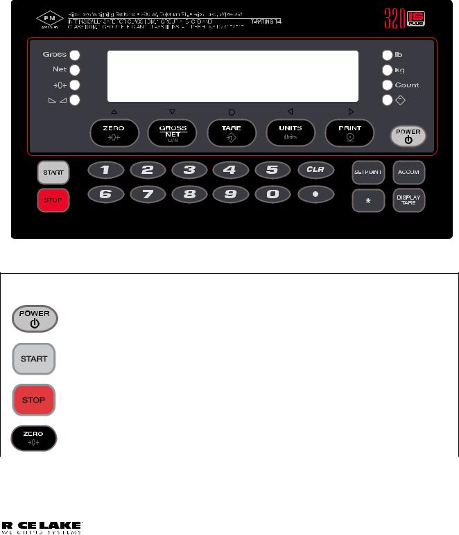
The 320IS Plus is a single-channel digital weight indicator designed and approved to operate as an intrinsically safe system in a wide variety of scale and weighing applications. The indicator is housed in a NEMA 4X/ IP66-rated stainless steel sealed case. The standard unit is equipped with a tilt stand base for tabletop or wall mounting applications. The indicator front panel consists of a large (0.8 in, 20 mm, 16-segment), six-digit LED display, 24-button keypad and eight LED annunciators. Features include:
•Drives up to four 350 or eight 700 load cells
•Supports fourand six-wire load cell connections (six-wire remote sense recommended)
•Full-duplex fiber optic interface to attach an external I/O board located in the safe area
The 320IS Plus is NTEP-certified and pending Measurement Canada approval for Classes I, II and III at 10,000 divisions. See Section 9.9 on page 80 for detailed specifications.
Available with optional I/O Module (PN 72721):
•Four configurable digital inputs
•Four digitally-controlled single pole single throw-normally open non-latching relay contact outputs
•Electronic data processing (EDP) port communications at up to 38400 bps for full duplex RS-232/ RS-422/RS-485 and Current loop
•Printer port communications at up to 38400 bps for full duplex RS-232/RS-422/RS-485 and Current loop
• Two 16–bit analog output channels provide ±10V or ±5V, 0-5V or 0-10V, and 4-20 mA tracking of gross or net weight values
1.2Factory Mutual Approval
The 320IS Plus is Factory Mutual (FM) Entity approved for:
•Classes I, II, and III
•Divisions 1 and 2
•Groups A, B, C, D, E, F and G
•T-rating T4
Only devices that have FM Entity Approval with proper entity parameters may be used unless specifically listed in this manual or control drawing PN 72717 as part of the Rice Lake Factory Mutual systems approval. Failure to comply with this voids the FM approval.
The classification of hazardous materials are different in the US and European standards. Because of this, the safety class of the 320IS Plus is declared in the following regulations:
•US standards: Class I, II, III, DIV1, Groups A-G
Substitution of components may impair intrinsic safety.
 WARNING To prevent ignition of flammable or combustible atmospheres, disconnect power before servicing.
1.3Operating Modes
The 320IS Plus has three modes of operation.
Normal (Primary) Mode
Normal mode is the default mode of the indicator. The indicator displays gross or net weights as indicated by LED annunciators (see Figure 1-1) to indicate scale status and the type of weight value displayed.
Setup Mode
Most of the procedures described in this manual require the indicator to be in setup mode including configuration and calibration.
To enter setup mode, remove the large fillister head screw from the enclosure backplate. Insert a non-metal screwdriver or a similar tool into the access hole and press the setup switch once. The indicator display changes to show the word CONFIG.
2320IS Plus Installation Manual
Test Mode
Test mode provides a number of diagnostic functions for the 320IS Plus indicator. Like setup mode, test mode is entered using the setup switch (Section 8.8 on page 70).
1.4Front Panel Keypad
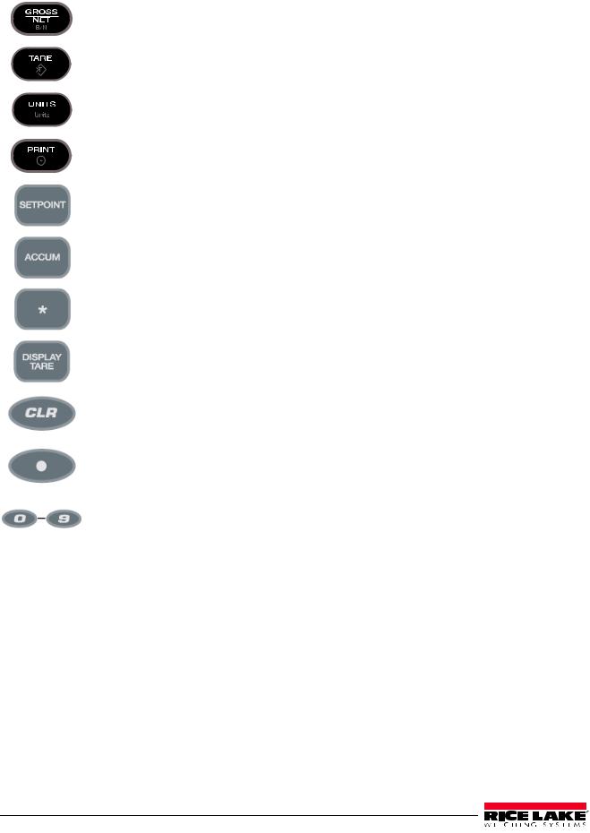
Figure 1-1 shows the 320IS Plus LED annunciators and keypad.
The symbols shown above the keys (representing up, down, enter, left, right) describe the key functions. In setup mode, the keys are used to navigate through menus, select digits within numeric values, and increment/ decrement values. See Section 1.5 on page 5 for information about using the front panel keys in setup mode.
Figure 1-1. 320IS Plus Front Panel
Key Functions
|
Normal |
Setup |
Test |
Count |
|
|
|
|
|
|
Turn the indicator on or off |
|
|
|
|
|
|
|
|
|
Batch start |
N/A |
N/A |
N/A |
|
|
|
|
|
|
Batch stop |
N/A |
N/A |
N/A |
|
|
|
|
|
|
Return gross weight |
• Move up (vertically) |
Exit |
N/A |
|
display to zero |
• Increment value |
|
|
|
|
• Exit (top level only) |
|
|
|
|
|
|
|
Table 1-1. Indicator Display Key Functions
|
|
|
|
|
|
|
|
|
|
|
|
|
|
|
|
|
|
|
|
|
|
|
|
|
|
320IS Plus Installation Manual - Introduction |
3 |
|
|
|
|
|
|
|
|
|
|
Toggle between gross, |
• Move down (vertically) |
N/A |
Toggle between gross, net |
|
|
|
|
|
net and piece count |
• Decrement value |
|
and piece count mode |
|
|
|
|
|
mode |
|
|
|
|
|
|
|
|
|
|
|
|
|
|
|
|
|
Press to enter an auto |
Enter |
Enter |
Perform a piece count |
|
|
|
|
|
tare or keyed tare |
|
|
|
|
|
|
|
|
|
|
|
|
|
|
|
|
|
Toggle between primary |
• Move left (horizontally) |
Move left (horizontally) |
Select a sample size |
|
|
|
|
|
and secondary units |
• Previous |
|
|
|
|
|
|
|
|
|
|
|
|
|
|
|
|
Print using GFMT |
Move right (horizontally) |
Print using CFMT |
|
|
|
|
|
|
|
|
|
|
|
|
|
|
|
|
|
|
|
|
|
|
|
|
• Turn on/off a setpoint |
N/A |
N/A |
N/A |
|
|
|
|
|
• View a setpoint |
|
|
|
|
|
|
|
|
• Edit a setpoint |
|
|
|
|
|
|
|
|
|
|
|
|
|
|
|
|
|
Display the current |
N/A |
N/A |
N/A |
|
|
|
|
|
accumulator value |
|
|
|
|
|
|
|
|
|
|
|
|
|
|
|
|
|
Time and date entry |
N/A |
N/A |
N/A |
|
|
|
|
|
|
|
|
|
|
|
|
|
|
Display the tare value |
N/A |
N/A |
Display the average piece |
|
|
|
|
|
|
|
|
weight |
|
|
|
|
|
|
|
|
|
|
|
|
|
|
Clear the displayed value |
Clear the displayed value |
N/A |
N/A |
|
|
|
|
|
|
|
|
|
|
|
|
|
|
Enter a decimal point |
Enter a decimal point |
N/A |
N/A |
|
|
|
|
|
|
|
|
|
|
|
|
|
|
Enter a numeric |
Enter a numeric |
N/A |
Enter a sample size |
|
|
|
|
|
parameter value |
parameter value |
|
|
|
|
|
|
|
|
|
|
|
Table 1-1. Indicator Display Key Functions
4320IS Plus Installation Manual
1.5Front Panel Configuration
Move Up and |
|
|
Move Left and |
Down (vertically) |
Enter |
Right (horizontally) |
|
Figure 1-2. Front Panel Key Functions in Setup Mode
Four front panel keys are used as directional keys to navigate through the menus in setup mode (see Figure 1-2). The UNITS ( ) and PRINT (
 ) keys scroll left and right (horizontally) on the same menu level; ZERO (
 ) and GROSS/NET (
 ) move up and down (vertically) to different menu levels. The TARE key (
 ) serves as an enter key for selecting parameter values within the menus. A label above each of these keys identifies the direction provided by the key when navigating through the setup menus.
1st Level
Parameter
1st Level
Parameter
2 nd Level |
|
|
2 nd Level |
Parameter |
|
|
Parameter |
Default value |
Value |
Value |
Value |
When moving through values below the first menu level, press  to return to the level above. Press
  or
or  to move to thenext parameter on the level above.
Figure 1-3. Setup Mode Menu Navigation
To select a parameter, press  or
or  to scroll left or right until the desired menu group appears on the display, then press
  to move down to the submenu or parameter you want. When moving through the menu parameters, the default or previously selected value appears first on the display.
To change a parameter value, scroll left or right to view the values for that parameter. When the desired value appears on the display, press  to select the value and move back up one level. To edit numerical values, use the navigation keys to select the digit and to increment or decrement the value or use the numeric keypad (see Figure 1-4).
0 0 0 0 0 0
When editing numeric values, press  or
or  to change th e digit selected. Press
  or
or  to increment or decrement the value of the selected digit, or use the numeric keypad.
Press  to save the value entered and return to the level above.
Figure 1-4. Editing Procedure for Numeric Values
|
|
|
|
|
|
|
|
|
|
|
|
|
|
|
|
|
|
|
|
|
|
|
|
|
|
320IS Plus Installation Manual - Introduction |
5 |
|
|
|
|
|
1.6LED Annunciators
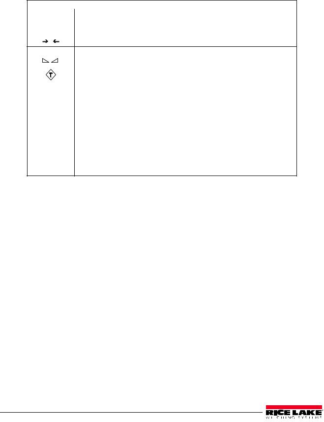
The 320IS Plus display uses eight LED annunciators to provide additional information about the value being displayed (see Figure 1-1 on page 3):
|
LED Annunciators |
Gross |
The Gross and Net annunciators are lit to show whether the displayed weight is a |
Net |
gross or net weight. |
|
|
Center of Zero |
Gross weight is ±0.25 graduations of zero. This annunciator lights when the scale is |
0zeroed.
Standstill |
Scale is at standstill or within the specified motion band. Some operations, including |
||||
|
|
|
|
tare functions and printing, can only be done when the standstill symbol is shown. |
|
|
|
|
|
|
|
|
|
|
|
The Tare Acquired light shows that a tare value has been entered. |
|
|
|
|
|
|
|
|
|
|
|
|
|
Count |
The Count annunciator is lit to show that the indicator is in piece count mode. |
||||
|
|
|
|
|
|
0 lb |
lb and kg annunciators indicate the units associated with the displayed value: |
||||
|
|
|
|
lb=pounds, kg=kilograms. Two units of measurement can be chosen to toggle |
|
0kg |
|||||
between. |
|||||
|
|
|
|
||
|
|
|
|
The displayed units can also be set to ounces (oz), short tons (tn), metric tons (t), |
|
|
|
|
|
grams (g), or they can be disabled. A user-defined unit can also be set as secondary |
|
|
|
|
|
unit by declaring a conversion factor in the setup menu. The lb and kg LED’s function |
|
|
|
|
|
as primary and secondary units annunciators for some combinations of primary and |
|
|
|
|
|
secondary units. If neither primary nor secondary units are lb, kg, oz, or g, the lb |
|
|
|
|
|
annunciator is lit for primary units, kg for secondary units. |
|
Table 1-2. LED Annunciators
Table 1-3 shows which annunciators are used for all combinations of configured primary and secondary units. For example:
•If the primary unit is pounds (lb) and the secondary unit is kilograms (kg), the lb LED is lit for primary units, kg for secondary units.
•If the primary unit is pounds (lb) and the secondary unit is short tons (tn), the lb LED is lit for primary units, kg for secondary units. There is no LED for short tons, so the kg LED is used as the secondary units annunciator.
•If the primary unit is short tons (tn) and the secondary unit is pounds (lb), the lb LED is lit for primary units (tn), and kg is lit for secondary units (lb). Because there is no LED for short tons, the lb and kg LEDs are used as primary and secondary units annunciators.
See Section 3.2.2 on page 25 for more information about configuring primary and secondary display units.
|
|
|
|
Secondary Unit |
|
|
|
||
|
|
|
|
|
|
|
|
|
|
Primary Unit |
lb |
kg |
oz |
|
tn |
|
t |
g |
none |
|
|
|
|
|
|
|
|
|
|
lb |
lb / lb |
lb / kg |
lb / kg |
|
lb / kg |
|
lb / kg |
lb / kg |
lb / kg |
kg |
kg / lb |
kg / kg |
kg / lb |
|
kg / lb |
|
kg / lb |
kg / lb |
kg / lb |
oz |
kg / lb |
lb / kg |
lb / kg |
|
lb / kg |
|
lb / kg |
lb / kg |
lb / kg |
tn |
kg / lb |
lb / kg |
lb / kg |
|
lb / kg |
|
lb / kg |
lb / kg |
lb / kg |
t |
kg / lb |
lb / kg |
lb / kg |
|
lb / kg |
|
lb / kg |
lb / kg |
lb / kg |
g |
kg / lb |
lb / kg |
lb / kg |
|
lb / kg |
|
lb / kg |
lb / kg |
lb / kg |
none |
kg / lb |
lb / kg |
lb / kg |
|
lb / kg |
|
lb / kg |
lb / kg |
lb / kg |
|
|
|
|
|
|
|
|
|
|
Table 1-3. Unit Annunciators, Primary/Secondary LEDs Used For All Configurations
6320IS Plus Installation Manual

1.7Indicator Operations
Basic 320IS Plus operations are summarized below.
1.7.1Toggle Gross/Net Mode
Press the GROSS/NET key to switch the display mode from gross to net, or from net to gross. If a tare value has
been entered or acquired, the net value is the gross weight minus the tare. The Tare( |
|
|
) annunciator is lit when |
|
|
||
a tare value is currently stored in memory. |
|
|
|
1.7.2Toggle Units
Press the UNITS key to switch between primary and secondary units. The appropriate units LED to the right of the display is lit.
1.7.3Zero Scale
1.In gross mode, remove all weight from the scale and wait for  .
.
2.Press the ZERO key.  0
0 annunciator lights to indicate the scale is zeroed.
1.7.4Acquire Tare
1.Place container on scale.
2.When  is lit, press the TARE. The indicator switches to net mode.
3.To display the current tare value, press the DISPLAY TARE .
1.7.5Remove Stored Tare Value
1.Remove all weight from the scale and wait for ( ).
).
2. When |
is lit, press the TARE . The indicator switches to gross mode, indicating the tare value has been |
removed. |
|
1.7.6Alternate Method to Remove Tare
1.In gross mode, press Display Tare.
2.Press CLEAR.
3.Display shows CLRTAR.
4.Press CLEAR. Indicator switches to gross mode. Inactive tare value has been removed.
1.7.7Acquire Parts Sample
1.Place empty parts container on scale.
2.Press TARE to acquire the tare weight of the container.
3.Press GROSS/NET to enter piece count mode.
 Note Press the CLEAR key to exit.
4.Press the UNITS key to enter sample acquisition mode.
Addnnn displays, nnn is the sample quantity to be placed on the scale.
•Add the number of parts shown.
•Choose a different sample size. Press the SAMPLE key to scroll through the selectable sample quantities (5, 10, 20, 50, 100) or use the numeric keypad to specify a custom sample size.
•Specify a known piece weight. Press the SAMPLE key to scroll through the selectable sample quantities until the PC WGT prompt is shown. Use the numeric keypad to enter the piece weight.
5.Once the sample quantity is on the scale, press ENTER to calibrate the indicator for counting the new parts.
6.If a sample size was specified, the indicator display shows the message –CNT– as it acquires the sample weight, then switches to count display mode and shows the part quantity.
7.If a known piece weight was specified, the display switches to count display mode immediately.
|
|
|
|
|
|
|
|
|
|
|
|
|
|
|
|
|
|
|
|
|
|
|
|
|
|
320IS Plus Installation Manual - Introduction |
7 |
|
|
|
|
|

1.7.8Display Part Weight
To view gross and net weight parts, press MODE to switch from count display mode to normal weighing mode. To view the current piece weight while in count mode, press DISPLAY TARE key.
1.7.9Display or Change Time/Date
 Note Requires optional I/O Module (PN 72721).
To display the date, press the asterisk (*) key once; press asterisk (*) a second time to display the time.
To set the date, press the asterisk (*) key once. Use the numeric keypad to enter the date, then press the ENTER key. Use the numeric keypad to enter the date in the same format configured for the indicator: MMDDYY, DDMMYY, or YYMMDD.
To set the time, press the asterisk (*) key twice. Use the numeric keypad to enter the time in 24-hour format, then press the ENTER key.
1.7.10Print Ticket
 Note Requires optional I/O Module (PN 72721).
Wait for the standstill annunciator ( |
). Press the PRINT key to send data to the serial port. Standstill must be |
lit to print. |
|
1.7.11Display or Change Setpoint Value
To display a setpoint value, press the SETPOINT key. To change the setpoint value, display the current value, then use the numeric keypad to enter the new value and press the ENTER key.
1.7.12Turn Setpoint On or Off
 Note Requires optional I/O Module (PN 72721).
To turn a setpoint off at the front panel. With the correct setpoint displayed, press CLEAR to turn the setpoint off.
To re-enable a setpoint that has been turned off at the front panel, press the SETPOINT key, then press ENTER to turn the setpoint back on.
1.7.13Display or Clear Accumulator
If the accumulator function is enabled, the current net weight is added to the accumulator each time the indicator performs a print operation.
•To display the current accumulator value, press the ACCUM key.
•To clear the accumulator, press ACCUM to show the current value, then press the CLEAR key twice to reset the accumulator.
8320IS Plus Installation Manual

2.0Installation
This section describes installation of load cells, power supply, fiber optics, and ferrite bead for the 320IS Plus indicator.
CAUTION |
Use a wrist strap to ground yourself and protect components from electrostatic discharge (ESD) when |
|
working inside the indicator enclosure. |
||
|
Component level repair, excluding board-swapping, is not permitted on Factory Mutual Approved |
|
Important |
||
equipment by anyone other than the manufacturer. It is mandatory to return the 320IS Plus to Rice |
||
|
Lake Weighing Systems for repairs. |
2.1Unpacking and Assembly
Immediately after unpacking, visually inspect the 320IS Plus to ensure all components are included and undamaged. The shipping carton should contain the indicator with attached tilt stand, this manual, and a parts kit. If any parts are missing or were damaged in shipment, notify Rice Lake Weighing Systems and the shipper immediately. See Table 2-5 on page 18 for parts kit.
2.2Enclosure Disassembly
The indicator enclosure must be opened to connect cables for load cells, communications, and power.
 WARNING Before opening the unit, ensure the power is disconnected from the power outlet.
1.Ensure power to the indicator is disconnected.
2.Place the indicator face-down on an antistatic work mat.
3.Remove the screws that hold the backplate to the enclosure body.
4.Lift the backplate away from the enclosure and set it aside.
|
|
|
|
|
|
|
|
|
|
|
|
|
|
|
|
|
|
|
|
|
|
|
|
|
|
320IS Plus Installation Manual - Installation |
9 |
|
|
|
|
|
2.3Hazardous Area Installation of the 320IS Plus
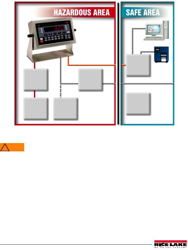
The following information is provided to help the installer with the correct installation of the 320IS Plus system. See Figure 2-1 below for a diagram of a typical intrinsically safe system.
Load Cell |
Fiber Optic |
I/O Module |
||
|
|
|||
|
Input |
|
|
(Optional) |
Junction |
|
|
AC Power |
|
Box |
|
VDC |
Supply |
115/230VAC |
(Optional) |
|
(Intrinsically |
||
|
|
|
||
|
|
|
Safe Output) |
|
|
|
|
|
Battery |
FM-Approved |
|
Battery |
|
Charger |
Load Cells |
(Optional) |
|
(Optional) |
|
(up to 4–350Ω)
Figure 2-1. Intrinsically Safe System Diagram
2.3.1Power Supply to Indicator
Do not, under any circumstances, connect or disconnect the DC wire from the indicator while the AC  WARNING power is applied to the power supply. This will cause the power supply fuse to blow.
The indicator should be powered by an FM-approved Rice Lake power supply or alternatively from an external battery pack. The power requirements of the 320IS Plus are as follows:
•Minimum input voltage: 5.8 V
•Maximum input voltage: 7.9 V
•Peak current consumption: 190 mA
•Average input current (with four load cells): 140 mA
The DC power cable should be attached to connector CN1 (see Table 2-1). Care must be taken to wire CN1 with the correct DC polarity. See Section 2.4 on page 11 for information on cabling through metal cord grips.
CN1 Pin |
Function |
Wire Color |
|
|
|
1 |
+ Voltage (5.8 – 7.9 V) |
Green |
|
|
|
2 |
Ground (V–, Common) |
Brown |
|
|
|
Table 2-1. DC Power Supply Connections
10 320IS Plus Installation Manual
A separate conduit system is recommended for installation. The type suggested for this application is 3/4" rigid steel conduit with pull boxes located at required intervals. The conduit provides additional noise protection for the low-level signals, while automatically complying with the requirements for two-inch separation between intrinsically safe circuits and other electrical cables. Conduit seals are necessary where a gas tight seal is required between hazardous area and safe area.
2.3.2AC Power Wiring
Standard units are powered by an FM-approved power supply. 100–240 VAC into RLWS IS-EPS-100-240 Intrinsically safe DC output power supply (PN 72713) is recommended.
See the IS-EPS-100-240 Power Supply Instruction Sheet (PN 79820) for information on wiring and power specifications.
2.3.3Battery Option
The optional battery pack provides an intrinsically safe battery that can replace the power supply. The battery is approved for use in hazardous environments and limited use operations such as bench scales and platform scales. A low battery error message will display to indicate that the battery needs to be recharged. Always charge the battery overnight. The yellow indicator light will remain on until the battery is charged at about 70%, at which point the indicator light will turn green and the charger will switch to float charge mode. Once the light turns green, the battery requires another 3 hours on float charge before the battery is fully charged.
 Note
Note
 Note
Note
To keep battery at full capacity, it is recommended to leave the battery connected to the charger, in float charge mode, until ready to use. The battery can remain on the charger in float charge mode indefinitely without damaging the battery. See Battery Charging Instruction Sheet (PN 96567) for instructions on charging the battery.
Load Cell Size |
Quantity of cells |
Operating Time |
|
|
|
350 load cell |
1 |
40 - 50 hours |
|
|
|
|
4 |
35 - 40 hours |
|
|
|
700 load cell |
1 |
45 - 55 hours |
|
|
|
|
4 |
40 - 50 hours |
|
|
|
Table 2-2. Estimated Battery Operating Times
While connected to the DC battery pack with the indicator off, the 320IS still draws a small amount of current that will shorten battery run time. To preserve battery life, disconnect the battery when not in use.
2.4Cable Connections and Installation
The following sections contain information on cable connections and installation for the 320IS Plus.


 Intrinsically safe cables are specified by control drawing. All cables must have appropriate internal
 Note inductance and capacitance. Cable lengths are based on group classifications.
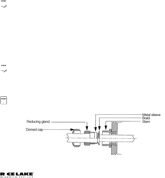
Figure 2-2. Metal Cord Grip
|
|
|
|
|
|
|
|
|
|
|
|
|
|
|
|
|
|
|
|
|
|
|
|
|
|
320IS Plus Installation Manual - Installation |
11 |
|
|
|
|
|
Before connecting the AC power to the power supply:
1.Determine the length of AC power cord necessary to reach from the AC power panel to the power supply where it is mounted.
2.Cut the AC power cord to that length. If you are mounting the I.S. power supply in a hazardous area, all AC power must be routed through approved conduit, where necessary make allowances in length of the conduit.
3.Install the AC power cord but do not hook up to the AC power.
Do not, under any circumstances, connect or disconnect the DC wire from the indicator while the AC  WARNING power is applied to the power supply. This will cause the power supply fuse to blow.
4.Determine the length of the DC power cord necessary to reach from the AC power supply to the 320IS Plus indicator and add 7" to that length.
5.Cut the DC power cord to that length.
2.4.1Braided Power Cable Connection with Ferrite Core
Use the following procedure for connecting braided power cable with the ferrite core:
1.If using the ferrite core, carefully remove 7" of the outer blue insulation and 6.5" of braid from the cable. If not using the ferrite core, go to Section 2.4.2.
2.Remove the reducing gland and metal sleeve from the center cord grip of the indicator. Place them on a work surface.
3.Remove the cap and reducing gland from the 320IS Plus parts kit.
The cap and reducing gland from the parts kit have larger holes. DO NOT confuse these parts with the parts removed from the cord grip of the indicator.
4.Take the metal sleeve (from step 2) and insert it into the reducing gland taken from the parts kit.
5.Place the domed cap and reducing gland that were removed from the 320IS cord grip, into the parts kit (to be used as spares).
6.Thread the DC cable through the domed cap, then through the reducing gland/metal sleeve combination.
7.Lower the reducing gland assembly so that the end of the metal sleeve is at the edge of the insulation and fold the braid over the metal sleeve (Figure 2-2). Trim the braid if necessary.
8.Trim the white wire back to match the end of the braid.
9.Tin the green and brown wire ends.
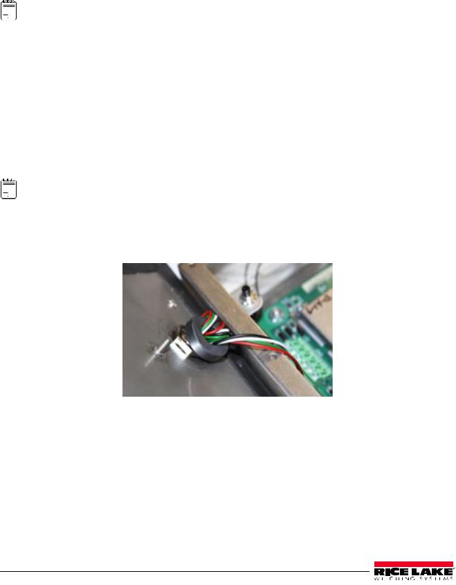
10.Thread the cable through the cord grip stem.

 Note Chassis ground is made through the braid compressed between the metal sleeve and the cord grip stem.
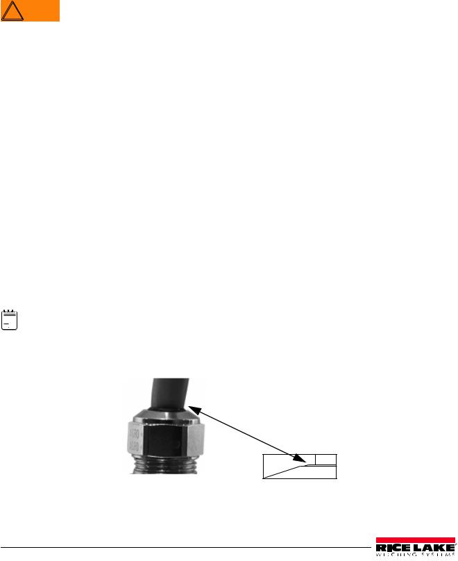
11.Lower the domed cap onto the cord grip stem and tighten until a small swelling of the rubber of the reducing gland appears between the domed cap and cable (see Figure 2-3).
Figure 2-3. Proper Cord Grip Compression
12 320IS Plus Installation Manual

12.Thread the green and brown wires two times through the ferrite core from the parts kit. See Figure 2-4 as an example picture.
13.Connect the green and brown wires to the connector for CN1, observing polarities. See Table 2-3 below.
CN Pin 1 |
Function |
Color |
|
|
|
1 |
+ Voltage (5.8 - 7.9) |
Green |
|
|
|
2 |
Ground (V-, Common) |
Brown |
|
|
|
Table 2-3. DC Power Supply Connections — CN1
14.Plug the connector onto CN1.
15.Connect the AC power.
2.4.2Braided Power Cable Connection Without Ferrite Core
Use the following procedure for connecting a braided power cable without a ferrite core.
1.If not using a ferrite core, carefully remove 3" of outer blue insulation and 2.5" of braid from the cable.
2.Remove the domed cap, reducing gland and the metal sleeve from the center cord grip of the indicator. Place them on a work surface.
3.Remove the domed cap and reducing gland from the 320IS Plus parts kit.


 The domed cap and reducing gland from the parts kit have larger holes. DO NOT confuse these parts with
 Note the parts removed from the cord grip.
4.Take the metal sleeve (from step 2) and insert it into the reducing gland taken from the parts kit.
5.Place the domed cap and reducing gland that were removed from the 320IS cord grip, into the parts kit (to be used as spares).
6.Thread the DC cable through the domed cap, then through the reducing gland/metal sleeve combination.
7.Lower the reducing gland assembly so that the end of the metal sleeve is at the edge of the insulation and fold the braid over the metal sleeve (Figure 2-2). Trim the braid if necessary.
8.Trim the white wire back to match the end of the braid.
9.Tin the end of the green and brown wires.
10.Thread the cable through the cord grip stem.
 Note Chassis ground is made through the braid compressed between the metal sleeve and the cord grip stem.
11.Lower the domed cap onto the cord grip stem and tighten until a small swelling of the rubber of the reducing gland appears between the domed cap and cable (see Figure 2-3).
12.Connect the green and brown wires to the connector for CN1. Observe polarity. See Table 2-3.
13.Plug the cable into CN1.
14.Connect the AC power.
2.4.3Braided Load Cell Cable Connection
Use the following procedure for connecting braided load cell cable:
If Using 6 Wire Load Cell Cable
1. Carefully remove 8" of outside insulation and 7 1/2" of braid from the load cell cable.
2. Remove the metal domed cap, reducing gland and metal sleeve from the left metal cord grip. Place them on a work surface.
3. Remove the reducing gland and metal domed cap from the 320IS plus parts kit.
 Note These have a larger hole than those removed from the cord grip — DO NOT confuse them.
4.Take the metal sleeve from step 2, and insert it into the reducing gland taken from the parts kit.
5.Retain the cord grips.
|
|
|
|
|
|
|
|
|
|
|
|
|
|
|
|
|
|
|
|
|
|
|
|
|
|
320IS Plus Installation Manual - Installation |
13 |
|
|
|
|
|
6.Thread the load cell cable through the domed cap, then through the reducing gland/metal sleeve assembly.
7.Lower the reducing gland assembly so that the end of the metal sleeve is at the edge of the insulation and fold the braid back over the sleeve (see Figure 2-2). Trim if necessary.
8.Thread the cable through the cord grip stem.
 Note Chassis ground is made through the braid compressed between the metal sleeve and the cord grip stem.
9.Lower the domed cap onto the cord grip stem and tighten until a small swelling of the rubber of the reducing gland appears between the dome cap and the cable (see Figure 2-3).
10.Thread the load cell cable through the ferrite core, from the parts kit, twice. Keep the ferrite core as close to the backplate as possible (see Figure 2-4).
If Using 4 Wire Load Cell Cable
1. Carefully remove 8" of outside insulation and 7 1/2" of braid from the load cell cable.
2. Remove the metal domed cap and reducing gland from cord grip, place them on a work surface.
3. Thread the load cell cable through the domed cap, then through the reducing gland/metal sleeve assembly.
4. Lower the reducing gland assembly so that the end of the metal sleeve is at the edge of the insulation and fold the braid back over the sleeve (see Figure 2-2). Trim if necessary.
5. Thread the cable through the cord grip stem.
 Note Chassis ground is made through the braid compressed between the metal sleeve and the cord grip stem.
6.Lower the domed cap onto the cord grip stem and tighten until a small swelling of the rubber of the reducing gland appears between the domed cap and the cable (see Figure 2-3).
7.Thread the load cell cable through the ferrite core, from the parts kit, twice. Keep the ferrite core as close to the backplate as possible (see Figure 2-4).
Figure 2-4. Ferrite Core Wire Wrap
2.4.4Foil Load Cell Cable Connection
Use the following procedure for connecting foil load cell cable:
1.Carefully remove 8" of insulation and 7 1/2" of foil from cable.
2.Remove domed cap, reducing gland and metal sleeve from cord grip and place them on the cable (see Figure 2-2).
3.Thread the load cell cable through the domed cap, then through the reducing gland metal sleeve assembly.
4.Lower reducing gland metal sleeve assembly to edge of insulation and wrap foil over metal sleeve of reducing gland leaving the silver side out.
5.Thread the cable through the cord grip stem.
14 320IS Plus Installation Manual
 Note Chassis ground is made through the foil compressed between the metal sleeve and the cord grip stem.
6.Lower the domed cap onto cord grip stem.
7.Tighten until a small swelling of the rubber between the domed cap and the cable builds (see Figure 2-3).
8.Thread wires through ferrite core two times. Keep the ferrite as close to the backplate as possible (see Figure 2-4).
9.Wire cable to connector CN3.
Blue opptical output
Black optical input
Sense jumpers 
J1 & J2
Load cell |
|
|
|
125mA fully – |
|
|
|
|
|
||
|
|
encapsulated |
|||
connector |
|
|
|||
|
|
fuses |
|||
|
|
|
|
||
|
|
|
|
F1 & F2 |
|
|
Power cable connector |
Chassis |
Ferrite cores |
Green = +Voltage |
|
Brown = Return |
ground |
Figure 2-5. Cable Connections
2.4.5Load Cells
To attach cable from a load cell or junction box, use six-position connector in parts kit. See Section 2.4 on page 11 for information on cabling through metal cord grips.
Wire the load cell cable from the load cell or junction box to connector CN3 as shown in Figure 2-6. If using 6-wire load cell cable (with sense wires), remove jumpers J1 and J2 before installing connector CN3. For four-wire installation, leave jumpers J1 and J2 on.
When connections are complete, reinstall connector CN3 on the board and use two cable ties to secure the load cell cable to the inside of the enclosure.
1 |
2 |
3 |
4 |
5 |
6 |
|
|
|
|
|
CN3 |
Excitation- |
Sense- |
Signal- |
+Signal |
+Sense |
+Excitation |
Figure 2-6. CN3 Load Cell Connections
|
|
|
|
|
|
|
|
|
|
|
|
|
|
|
|
|
|
|
|
|
|
|
|
|
|
320IS Plus Installation Manual - Installation |
15 |
|
|
|
|
|
Pin |
Function |
|
|
1 |
-Excitation |
|
|
2 |
-Sense |
|
|
3 |
-Signal |
|
|
4 |
+Signal |
|
|
5 |
+Sense |
|
|
6 |
+Excitation |
|
|
• For six-wire connections, remove jumpers J1 and J2.
• For four-wire connections, leave jumpers J1 and J2 on.
Table 2-4. CN3 Pin Assignments
2.5Fiber Optics Installation
The 320IS Plus is equipped with a duplex fiber optic port for communicating with an I/O Module located outside the hazardous area. This is the only communications channel of the indicator. The indicator communicates with external devices through the optional I/O Module’s physical interfaces (RS–232, RS–422, RS–485, Current Loop) and provides analog and digital I/O functions such as setpoint relays and analog outputs.
The fiber optics port is located on the indicator CPU board (see Figure 2-5).
2.5.1Assembling Fiber Optics Connectors
Use the following steps for assembling the fiber optic connectors of the 320IS Plus:
1.Cut off the ends of the fiber optic cable (PN 74000) with a single-edge razor blade or hot knife (PN 85548). Try to obtain a precise 90º angle.
2.Insert the fiber through the locking nut and into the connector until the core tip seats against the internal micro-lens.
3.Screw the connector locking nut down to a snug fit, locking the fiber in place.
4.Secure fiber with 3-inch nylon cable ties in parts kit and 3/4-inch square nylon mounts.
Mounting Hole |
Lens |
Device 


Optical Fiber
Housing |
Locking Nut |
LED
Positioning Foot
Figure 2-7. Fiber Optics Connector
2.6Enclosure Reassembly
1.Position the backplate over the enclosure.
2.Reinstall the backplate screws. Use the torque pattern shown in Figure 2-8 to prevent distorting the backplate gasket. Torque screws to 15 in-lb (1.7 N-m).
Important |
Torqued screws may become less tight as the gasket is compressed during torque pattern, therefore a |
|||||
second torque is required using the same pattern and torque value. |
||||||
|
|
|
|
|
|
|
|
|
|
|
|
|
|
|
|
|
|
|
|
|
|
|
|
|
|
|
|
|
|
|
|
|
|
|
16 320IS Plus Installation Manual
Torque pattern 10 |
8 |
4 |
|
Setup switch access screw |
|
|
|
Load cell connection cord grip |
|
|
5 |
|
DC power cord grip |
6 |
|
|
Fiber optics |
|
|
|
cord grip |
|
|
Fillister head screws |
Ground lug |
|
|
|
|
|
3 |
7 |
9 |
2 |
Figure 2-8. 320IS Plus Enclosure Backplate
|
|
|
|
|
|
3 |
$ |
|
|
+ |
|
|
|
|
|
|
|
|
|
|
|
|
|
|
-% |
|
|
|
|
|
|
|
|
|
|
|
|
|
3 |
|
|
$ |
|
|
|
|
|
|
|
|
|
|
|
|
|
|
|
|
|
|
|
|
|
||||
|
|
|
$ |
|
|
|
|
|
|
$ |
|
|
|
|
|
|
|
|
|
|
|
|
|
|
|
|
|
||||||
|
|
|
|
|
|
|
|
|
|
|
|
|
|
|
|
|
|
|
|
|
|
0QUJDBM 0VUQVU |
|
|
|
||||||||
|
|
|
|
|
|
|
|
|
|
|
|
|
|
|
|
|
|
|
|
|
|
|
|
|
|
|
|||||||
|
|
51 |
|
|
|
|
|
|
6 |
|
|
|
|
|
|
|
|
|
|
|
|
$ |
|
|
|
|
3$ |
3 |
|
|
|||
|
. |
|
|
|
|
|
|
|
|
|
|
|
|
|
|
|
|
|
6 |
|
|
|
|
|
|
. |
|||||||
|
|
|
|
|
|
|
|
|
|
|
|
|
|
|
|
$ |
|
|
|
|
|
|
|
3 |
|
||||||||
|
|
|
|
|
|
|
|
|
|
|
|
|
|
|
|
|
|
|
|
|
|
|
|
|
|
|
|
|
|||||
|
|
|
|
|
|
|
|
|
|
|
|
|
|
|
|
|
|
|
|
|
|
|
|
9 |
|
|
|
|
|
|
$ |
|
|
|
|
|
9 |
|
|
|
|
|
|
|
|
|
|
|
|
|
|
|
|
|
|
|
|
|
|
6 |
|
$ |
|
|
|
||
|
|
51 |
|
|
|
|
|
|
|
|
|
|
|
|
|
|
|
|
|
|
|
|
|
|
|
|
|
|
|
||||
|
4&561 48 |
|
|
|
|
|
|
|
|
|
|
|
|
|
|
|
|
|
|
|
|
|
|
|
|
|
|
|
|
|
|
||
|
$ |
6 |
|
|
|
|
|
|
|
|
|
6 |
|
|
$ |
|
|
|
$ |
|
|
|
|
|
0QUJDBM *OQVU |
|
|
|
|||||
|
$ |
|
|
|
|
|
|
|
|
|
|
|
|
6 |
|
|
|
6 |
1% |
|
|
|
|
|
|
|
|
||||||
|
|
|
|
|
|
|
|
6 |
|
|
|
|
|
|
|
|
|
|
|
|
|
|
|
|
|||||||||
|
|
|
|
|
|
|
6 |
|
|
6 |
|
|
|
|
|
|
|
|
*' % |
|
|
2 |
|
.&$$" |
|||||||||
|
|
|
|
|
|
|
|
|
|
|
|
|
|
|
|
|
|
|
|
|
|
|
|
|
|||||||||
|
|
|
|
|
|
$ |
|
|
$ |
|
|
|
|
|
2 |
|
|
|
|
|
|
|
|
|
|||||||||
|
|
MC |
6 |
|
|
|
|
|
|
|
3 |
$ |
|
|
|
|
|
|
|
|
|
2 |
|
|
|
2 |
|
|
|
||||
|
|
|
|
|
|
%4 |
|
|
%4 |
|
|
%4 |
|
|
|
|
%4 |
3 |
%4 |
3 |
5 |
|
|
||||||||||
|
|
|
|
|
|
|
|
|
|
|
%4 |
|
|
2 |
|
|
|
2 |
|
|
|
|
" |
|
|
||||||||
|
|
|
|
|
|
|
|
|
|
|
|
|
|
|
|
|
|
|
|
|
|
|
|
|
|
3 |
|
|
|||||
|
|
|
|
|
|
|
|
|
|
|
|
|
|
|
|
|
3 |
|
|
|
|
|
|
3 |
2 |
|
|
|
|
& |
|
|
|
|
|
|
|
|
|
|
|
|
|
|
|
|
|
|
|
|
|
|
|
|
|
|
|
|
|
2 |
|
|
; |
||||
|
|
|
|
|
|
|
|
|
|
|
|
|
|
|
|
|
3 |
|
|
|
|
|
|
|
|
|
|
|
3 |
/ |
|
||
|
|
LH |
|
|
|
|
|
|
|
|
2 |
|
|
|
|
|
|
|
|
3 |
|
|
|
|
|
|
|
|
|||||
|
|
|
|
|
|
|
|
|
|
|
2 |
|
|
|
|
|
|
|
3 |
|
|
|
|
|
|
& |
|
3 |
|||||
|
|
|
|
|
|
|
|
|
|
|
|
|
|
2 |
|
|
3 |
|
|
|
|
|
|
|
|||||||||
|
|
|
3 |
|
|
|
|
|
|
|
|
2 |
|
|
|
|
|
|
|
|
|
|
2 |
|
|
|
|
5 |
|
||||
|
|
|
|
|
|
|
|
|
|
|
|
|
|
|
2 |
|
|
|
|
2 |
3 |
|
|
|
|
; |
|
|
|||||
|
|
|
|
|
|
|
|
|
|
|
|
|
|
|
|
|
|
|
|
|
|
|
|
2 |
6 |
||||||||
|
|
P[ |
%(/% |
|
|
|
|
|
|
|
|
3 |
|
|
3 |
|
|
|
|
|
|
|
|
|
|
|
|
|
|
& |
|||
|
|
|
|
|
|
|
|
|
|
|
|
|
|
'2 |
3 |
|
|
|
|
|
|
|
2 |
|
3 |
|
3 |
|
|
||||
|
|
|
|
|
|
|
|
|
|
|
|
|
|
2 |
|
|
|
|
2 |
|
|
2 |
|
|
|
|
|
0 |
|
|
|||
|
|
|
|
|
|
|
|
|
|
|
|
3 |
|
|
|
|
|
|
|
|
3 |
|
|
|
|
|
|
|
|||||
|
|
|
(/% |
|
|
|
|
|
|
|
|
|
|
|
|
|
|
|
|
|
|
|
|
|
|
|
|
|
. |
|
|
||
|
|
H |
|
|
|
|
|
|
|
|
|
2 |
|
|
|
|
|
|
|
|
|
|
|
|
|
|
|
|
|
|
|
|
|
|
|
|
|
|
2 |
|
|
|
|
|
|
|
|
|
|
|
|
|
|
|
|
|
|
|
|
|
|
0 |
|
|
|||
|
|
|
|
|
|
|
|
|
|
|
|
|
|
|
|
|
|
|
|
|
|
|
|
|
|
|
3 |
2 |
5 |
|
3 |
||
|
|
|
|
|
|
|
|
|
|
|
|
|
|
|
|
|
|
|
|
|
|
|
|
|
|
; |
; |
|
; $ |
6 |
|||
|
|
|
|
|
|
|
|
|
|
|
|
|
|
|
|
|
|
|
|
|
|
|
|
|
|
|
|
|
3 |
||||
|
|
|
|
|
|
|
|
|
|
|
|
|
|
|
|
|
|
|
|
|
|
|
|
|
|
|
|
|
|
|
|
|
|
|
|
|
|
|
|
|
|
|
|
|
|
|
|
|
|
|
|
|
|
|
|
|
|
|
|
|
|
|
|
|
|
|
3 |
|
|
|
|
|
|
|
|
3 |
9 |
|
|
|
3 |
$ |
6 |
6 |
|
|
|
|
|
|
|
|
|
|
|
|
|
|
|
||
|
|
|
|
|
|
|
|
|
|
|
|
|
|
|
|
|
|
|
|
|
|
|
|
$ |
|
|
$ |
||||||
|
|
|
|
|
|
|
|
|
|
|
$$ |
|
|
|
|
|
|
|
|
|
|
|
|
|
|
|
|
||||||
|
|
|
|
|
$ |
|
|
|
|
|
|
|
|
|
|
|
|
|
|
; |
|
|
6 |
|
|
|
|
; |
|||||
|
|
|
|
|
|
3 |
|
|
|
3 |
|
- |
|
|
|
|
|
|
$ |
|
|
|
|
|
|
|
|
|
|
|
|||
|
|
|
|
$ |
$ |
|
|
|
|
|
|
|
|
|
|
|
|
|
|
|
|
|
|
|
|
|
|
||||||
|
|
|
|
|
|
|
$ |
|
|
|
|
|
|
|
|
|
|
; |
|
|
|
|
|
|
|
|
|
; |
|||||
|
|
|
|
|
|
|
|
|
|
|
$ |
|
$ |
|
|
$ |
6 |
|
,&:1"% |
|
|
|
|
|
|
|
|
|
|||||
|
|
|
$ |
|
|
|
|
|
|
|
|
|
|
|
|
|
|
|
|
|
|
|
3 |
|
3 |
|
|
|
|
||||
3'* "( |
|
|
|
|
|
|
|
|
|
|
|
|
|
|
|
*4 |
|
; |
|
|
6 |
|
|
|
|
; |
|||||||
|
|
|
|
|
|
|
6 |
|
|
|
|
|
$ |
|
|
|
|
|
|
|
|
|
|
|
|
|
|
||||||
|
|
- |
|
|
|
|
|
|
$ |
3 |
$ |
|
|
|
|
|
|
*4 |
$ |
|
|
|
|
|
|
|
|
|
|
( & |
|||
|
|
|
|
|
|
|
|
3 |
|
|
|
|
|
|
|
|
|
|
|
|
|
|
|
|
|
|
|
||||||
|
|
|
|
|
|
|
|
|
|
|
|
|
|
|
|
|
|
|
|
|
|
|
|
|
|
|
|
|
|||||
&(3'* |
|
|
$ |
$ $ $ |
|
|
$ $ |
|
$ |
|
3 |
$ |
$$ |
$ |
|
|
- |
|
$ |
|
|
|
|
|
|
|
|
||||||
|
|
|
|
|
|
|
|
|
|
|
|
|
.&$$" |
|
|
|
|
||||||||||||||||
|
|
|
|
|
|
|
|
|
|
|
3 |
|
|
|
% |
|
|
|
|
|
|
||||||||||||
|
|
|
|
|
|
|
|
|
|
|
|
|
$ |
|
3 |
3 |
3 |
|
|
|
|
|
|
|
|
|
|
||||||
|
|
|
|
|
|
|
|
|
|
|
|
|
|
|
|
|
|
|
|
|
|
|
|
|
|
||||||||
|
|
|
|
|
|
|
|
|
|
|
|
|
|
|
3 |
|
|
|
|
|
|
|
|
|
|
|
|||||||
|
. |
|
&(574 |
|
|
+ |
|
|
|
|
|
|
"(574 |
|
|
|
|
|
|
|
|
|
|
|
6 |
|
|
|
6 |
$ |
|
. |
|
|
|
|
|
|
|
$/ |
|
|
+ |
|
|
3/ |
|
|
|
|
|
|
|
|
|
|
|
|
|
||||||||
|
|
|
|
|
|
|
|
|
|
$ |
|
|
|
|
|
|
|
|
$ |
|
|
' |
|
|
|||||||||
|
|
|
|
|
|
|
|
|
|
|
|
|
$/ |
3 |
3/ |
$ |
|
$ |
|
|
' |
|
|
|
|
|
|
||||||
|
|
|
|
|
|
$/ |
|
|
|
|
$POOFDUPS |
$/ |
|
|
|
|
|
|
|
|
|||||||||||||
|
|
|
% |
|
|
|
|
|
|
|
% |
|
|
|
|
|
1PXFS |
|
|
|
|
|
|
|
|
||||||||
|
|
|
|
|
|
|
|
|
|
|
|
|
|
|
|
|
|
|
|
|
|
|
|
|
|
||||||||
|
|
|
|
|
|
|
|
|
|
|
|
% |
|
|
|
$ |
|
|
|
|
|
|
|
|
|
|
|||||||
|
|
|
|
|
|
|
|
|
|
|
|
|
|
|
|
|
|
|
|
|
|
|
|
|
|
||||||||
|
|
|
|
% |
&9 |
4& |
4* |
4* |
4& |
&9 |
|
|
|
|
|
|
|
|
3/ |
|
(/% |
|
|
|
|
|
|
|
|
|
|||
|
|
|
|
|
|
|
|
|
|
|
|
|
|
|
|
|
|
|
|
|
|
|
|||||||||||
|
|
|
|
|
|
|
|
-PBE $FMM $POOFDUPS |
|
|
|
|
|
|
|
|
|
|
|
|
|
|
|
|
|
|
|
|
|
|
|||
Figure 2-9. 320IS Plus CPU Board
|
|
|
|
|
|
|
|
|
|
|
|
|
|
|
|
|
|
|
|
|
|
|
|
|
|
320IS Plus Installation Manual - Installation |
17 |
|
|
|
|
|

Part Number |
Description (Quantity) |
Part Number |
Description (Quantity) |
|
|
|
|
45043 |
4 in. W/No. 8 Ground Wire |
14626 |
8–32NC Hex Kep Nut |
|
|
|
|
16892 |
Earth Ground Label |
19538 |
1.25 x 1 Slotted Black Post |
|
|
|
|
15627 |
PG–9 Metal Lock Nut |
91852 |
PG–9 Metal Cord Grip |
|
|
|
|
15626 |
PG–9 Black Cord Grip |
82432 |
125 mA Encapsulated Time–Lag Fuse |
|
|
|
|
50962 |
PCN–9 Black Nut |
72916 |
Backplate |
|
|
|
|
45042 |
SS Bonded Sealing Washer, #8 |
14862 |
8–32NC x 3/8 Screw |
|
|
|
|
39037 |
Backplate Gasket |
68216 |
Rice Lake Nameplate |
|
|
|
|
42640 |
1/4 – 28NF x 1/4 Screw |
44676 |
Bonded Sealing Washer, 1/4" |
|
|
|
|
29635 |
SS Tilt Stand |
68403 |
1/4 – 20 Two-Prong Black Knob |
|
|
|
|
15144 |
1/4 x 1 x 1/16 Nylon Washer |
|
|
|
|
|
|
100345 |
Reconditioned/Exchange 320IS Plus |
|
|
|
|
|
|
Table 2-5. Hardware Replacement List
18 320IS Plus Installation Manual

2.7Control Drawings
|
|
|
|
|
|
|
|
|
|
|
|
|
|
|
|
|
|
|
|
|
|
|
|
|
|
320IS Plus Installation Manual - Installation |
19 |
|
|
|
|
|
20 320IS Plus Installation Manual

3.0Configuration
To configure the 320IS Plus indicator, the indicator must be placed in setup mode. The setup switch is accessed by removing the large fillister head screw on the enclosure backplate. Setup mode is enabled by inserting a non-metallic screwdriver into the access hole and pressing the pushbutton configuration switch.
SERIAL, PFORMT, SETPNT, DIGIN, and ALGOUT functions require fiber optics communications with I/O

 Note module in order to operate.
When the indicator is placed in setup mode, the word CONFIG is shown on the display. The CONFIG menu is the first of nine main menus used to configure the indicator. See Section 3.2 on page 22. When configuration is complete, scroll to the CONFIG menu then press the  (ZERO) key to exit setup mode. Replace the setup switch access screw.
3.1Configuration Methods
The 320IS Plus indicator can be configured by:
•front panel keys (see section 3.2)
•sending commands or configuration data to the EDP port of the optional I/O Module
Configuration using the EDP port can be accomplished using either the EDP command set described in Section 5.0 on page 44 or the Revolution® configuration software.
3.1.1Revolution Configuration
The Revolution configuration software is the preferred method for configuring the 320IS Plus indicator. Download Revolution on a computer to set the configuration parameters for the indicator. When Revolution configuration is complete, configuration data can be downloaded to the indicator through the optional I/O Module’s EDP port.
Revolution supports both uploading and downloading of indicator configuration data. This capability allows configuration data to be retrieved from one indicator, edited, then downloaded to another.
To use Revolution, do the following:
1.Install Revolution on a computer running Windows® 98 or later. Minimum system requirements are 32MB of system RAM (64MB for NT4/2000/XP) and at least 40MB of available hard disk space.
2.With both the I/O Module and indicator powered off, connect the PC serial port to the RS-232 pins on the I/O Module’s EDP port (See Section 8.0 on page 61 for terminal pin diagrams).
3.Power up the I/O Module and the indicator. Use the setup switch to place the indicator in setup mode.
4.Start the Revolution program.
Revolution provides online help for each of its configuration sections. Parameter descriptions provided in this manual for front panel configuration can also be used when configuring the indicator using Revolution: the interface is different, but the parameters are the same.
3.1.2EDP Command Configuration
The EDP command set can be used to configure the 320IS Plus indicator using a personal computer, terminal, or remote keyboard. EDP command configuration sends commands to the indicator EDP port; commands can be sent using any external device capable of sending ASCII characters over a serial connection.
EDP commands duplicate the functions available using the indicator front panel and provide some functions not otherwise available. EDP commands can be used to simulate pressing front panel keys, to configure the indicator, or to dump lists of parameter settings. See Section 5.0 on page 44 for more information about using the EDP command set.
3.1.3Front Panel Configuration
The 320IS Plus indicator can be configured using a series of menus accessed through the indicator front panel when the indicator is in setup mode. Table 3-1 summarizes the functions of each of the main menus.
|
|
|
|
|
|
|
|
|
|
|
|
|
|
|
|
|
|
|
|
|
|
|
|
|
|
320IS Plus Installation Manual - Configuration |
21 |
|
|
|
|
|
Loading...