


PTG53-PVN
Rheem PTG53-PVN, RUTG2-53PVN, PTG53-PVP, PTG53-XN, PTG53-XP User Manual
...
AP14016-1 (04/06)
FOR YOUR SAFETY!
— Do not store or use gasoline or other
flammable vapors or liquids or other
combustible materials in the vicinity of this
or any other appliance. To do so may result
in an explosion or fire.
— WHAT TO DO IF YOU SMELL GAS
● Do not try to light any appliance.
● Do not touch any electrical switch; do not
use any phone in your building.
● Immediately call your gas supplier
from a neighbor’s phone. Follow the
gas supplier’s instructions.
● If you cannot reach your gas supplier, call
the fire department.
● Do not return to your home until authorized
by the gas supplier or fire department.
— Improper installation, adjustment,
alteration, service or maintenance can cause
property damage, personal injury or death.
Refer to this manual. Installation and service
must be performed by a qualified installer,
service agency or the gas supplier.
WARNING: If the information in these instructions is not followed exactly,
a fire or explosion may result, causing property damage, personal injury or death.
The purpose of this manual is twofold: one, to provide the installer with
the basic directions and recommendations for the proper installation and
adjustment of the water heater; and two, to the owner–operator, to
explain the features, operation, safety precautions, maintenance and
troubleshooting of the water heater. This manual also includes a parts
list.
It is very important that all persons who are expected to install, operate
or adjust this water heater read the instructions carefully so they may
understand how to perform these operations. If you don’t understand
these instructions or any terms within it, seek professional assistance.
Any questions regarding the operation, maintenance, service or
warranty of this water heater should be directed to the seller from whom
it was purchased. If additional information is required, refer to the
section on If You Need Service.
Do not destroy this manual. Please read carefully and keep in a safe
place for future reference.
Recognize this symbol as an indication of Important Safety
Information!
California Proposition 65 Warning: This product contains
chemicals known to the State of California to cause cancer, birth
defects or other reproductive harm.
Use & Care Manual
With Installation Instructions for the Installer
Printed in Japan
Tankless Water Heater
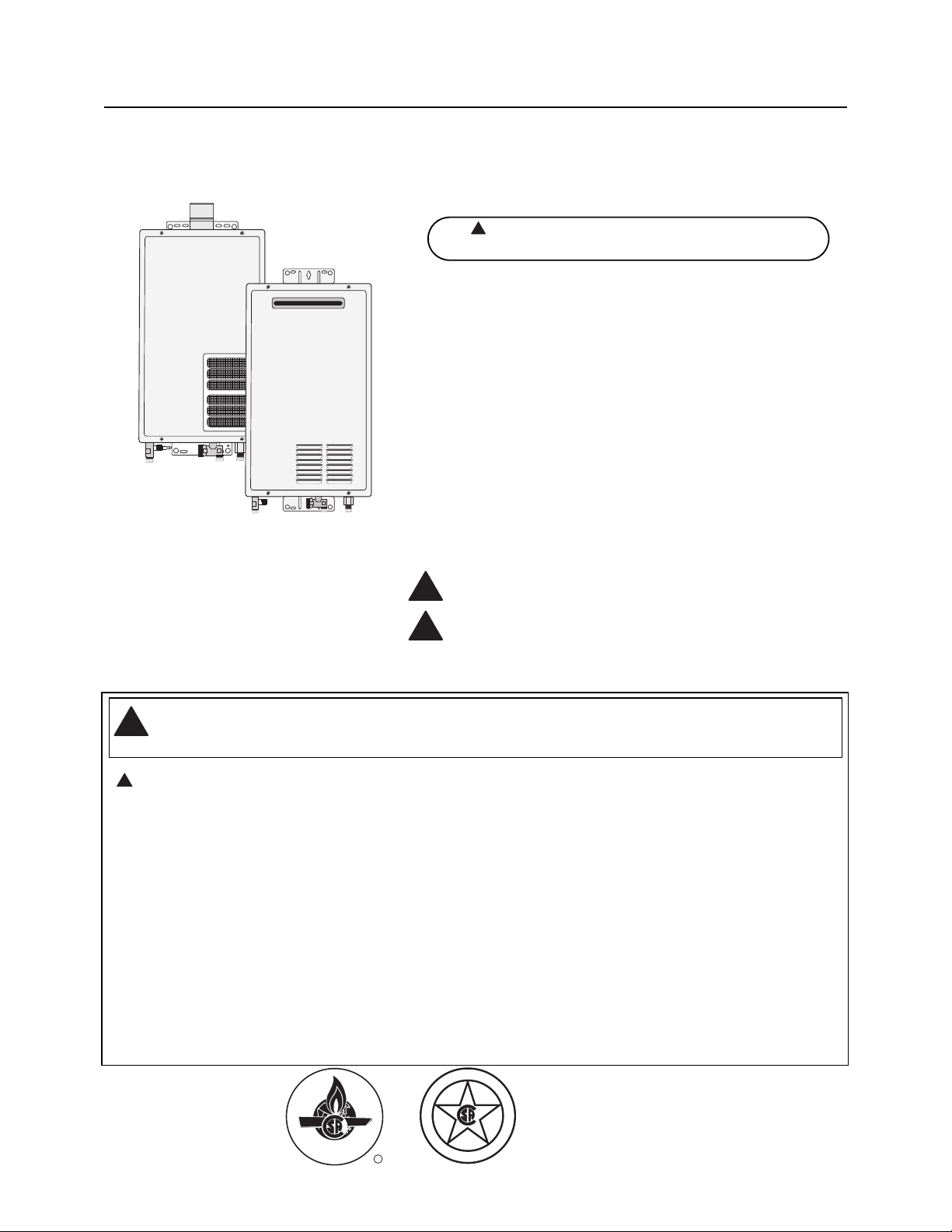
Warning: This water heater is not suitable
for use in manufactured (mobile) homes!
Indoor and Outdoor Gas
31-80176
PH-16 (FISN)(FISP)
PH20R-(IFSN)(IFSP)(OFN)(OFP)
PTG2-42(PVN)(PVP)
PTG53-(PVN)(PVP)(XN)(XP)
RTG2-42(PVN)(PVP)
RTG2-53(PVN)(PVP)(XN)(XP)
RUTG2-42(PVN)(PVP)
RUTG-53(PVN)(PVP)(XN)(XP)
RMTG2-42(PVN)(PVP)
RMTG-53(PVN)(PVP)(XN)(XP)
Models:
!
Indoor Water Heater
Outdoor Water Heater
!
!
!
!
I
S
G
E
N
D
CERTIFIED
C
E
D
R
E
I
T
F
I
R
®
Safety Information
Safety Precautions . . . . . . . 3–6
LP Gas Models . . . . . . . . . . . 5
Installation Instructions
Location, Outdoor. . . . . . . . . . 7
Location, Indoor . . . . . . . . . 8, 9
Venting . . . . . . . . . . . . . . 10-15
Water Connections. . . . . 16-18
Gas Supply. . . . . . . . . . . . . . 19
High Altitude . . . . . . . . . . . . 19
Remote Control . . . . . . . 20, 21
Electrical Connection . . . . . . 22
Typical Installation . . . . . . . . 23
Pipe Insulation . . . . . . . . . . . 24
Installation Checklist . . . . . . 25
Operating Instructions
Lighting Instructions . . . . . . 26
Water Temperature. . . . . 27, 28
Care and Cleaning
Maintenance. . . . . . . . . . . . . 29
Housekeeping . . . . . . . . 29, 30
Vent Inspection . . . . . . . . . . . 30
Burner Inspection . . . . . . . . 30
Extended Shut-Down . . . . . . 30
Draining . . . . . . . . . . . . . . . . 31
Freeze Protection . . . . . . . . . 31
Troubleshooting Tips
Before You Call
For Service. . . . . . . . . . . 32, 33
Customer Service
Parts List. . . . . . . . . . . . . . . . 34
If You Need Service. . . . . . . 36
Inside you will find many helpful hints on how to use and
maintain your water heater properly. A little preventive care on
your part can save you time and money over the life of your
water heater.
You’ll find many answers to common problems in the
Troubleshooting Guide. If you review the chart of
Troubleshooting Tips first, you may not need to call for service.
READ THIS MANUAL
FOR YOUR RECORDS
Write the model and serial numbers here:
#
#
You can find them on a label on the appliance.
Staple sales slip or cancelled check here.
Proof of the original purchase date is needed to obtain service
under the warranty.
2
Your safety and the safety of others are very important. There
are many important safety messages in this manual and on
your appliance. Always read and obey all safety messages.
This is the safety alert symbol. Recognize this symbol
as an indication of Important Safety Information!
This symbol alerts you to potential hazards that can
kill or hurt you and others.
All safety messages will follow the safety alert symbol and
either the word “DANGER”, “WARNING”, “CAUTION”
or “NOTICE”.
These words mean:
DANGER
An imminently hazardous situation
that will result in death or serious
injury.
WARNING
A potentially hazardous situation that
could result in death or serious injury
and/or damage to property.
CAUTION A potentially hazardous situation that
may result in minor or moderate
injury.
Notice:
Attention is called to observe a
specified procedure or maintain
a specific condition.
READ THE SAFETY INFORMATION
Qualified Installers Only!
Dip Switch Adjustment . . . 35
!
!
!
!
Be sure to read and understand the entire Use and Care Manual before attempting to install or operate this
water heater. It may save you time and money. Pay particular attention to the Safety Instructions. Failure to
follow these warnings could result in serious bodily injury or death. Should you have problems understanding
the instructions in this manual, or have any questions, STOP, and get help from a qualified service technician,
or the local gas utility.
IMPORTANT SAFETY INFORMATION.
READ ALL INSTRUCTIONS BEFORE USING.
3
Failure to install and properly vent the water heater to the outdoors as outlined in the
Venting Section of the Installation Instructions in this manual can result in unsafe operation
of the water heater. To avoid the risk of fire, explosion or asphyxiation from carbon
monoxide, never operate this water heater unless it is properly vented and has an adequate
air supply for proper operation.
Be sure to inspect the vent outlet on the OUTDOOR water heater, or the vent terminal and
the vent system on the INDOOR water heater for proper installation at initial start-up; and
at least annually thereafter. Refer to the Care and Cleaning section of this manual for more
information regarding vent system inspection.
DANGER!
INSTALL AND PROPERLY VENT THE WATER HEATER…
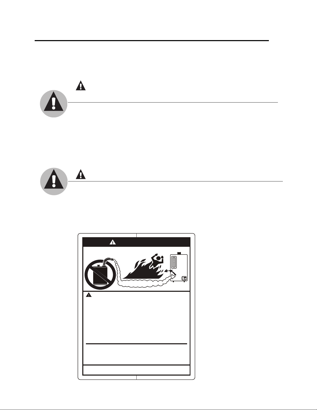
Gasoline, as well as other flammable materials and liquids (adhesives, solvents, paint
thinners etc.), and the vapors they produce are extremely dangerous. DO NOT handle, use
or store gasoline or other flammable or combustible materials anywhere near or in the
vicinity of a water heater or any other appliance. Be sure to read and follow the labels on
the water heater, as well as the warnings printed in this manual. Failure to do so can result
in property damage, bodily injury or death.
WARNING!
DANGER
FLAMMABLES
Vapors from flammable
liquids will explode and
catch fire causing death or
severe burns.
Do not use or store flammable
products such as gasoline,
solvents or adhesives in the
same room or area near the
water heater.
Keep flammable products:
1. far away from heater,
2. in approved containers,
3. tightly closed and
4. out of children's reach.
Installation:
Do not install water heater
where flammable products will
be stored or used unless the
main burner flame is at least
Read and follow water heater warnings and instructions. If
owners manual is missing, contact the retailer or manufacturer.
Flammable Vapors
Water heater has a main
burner flame.
The main burner flame:
1. which c an come on
at any time and
2. will ignite flammable
vapo rs.
Vapors:
1. cannot be seen,
2. are heavier than air,
3. go a long way on the
floo r and
4. can be carried from
other rooms to the
main burner flame by
air currents.
18" above the floor. This will
reduce, but not eliminate, the
risk of vapors being ignited
by the main burner flame.
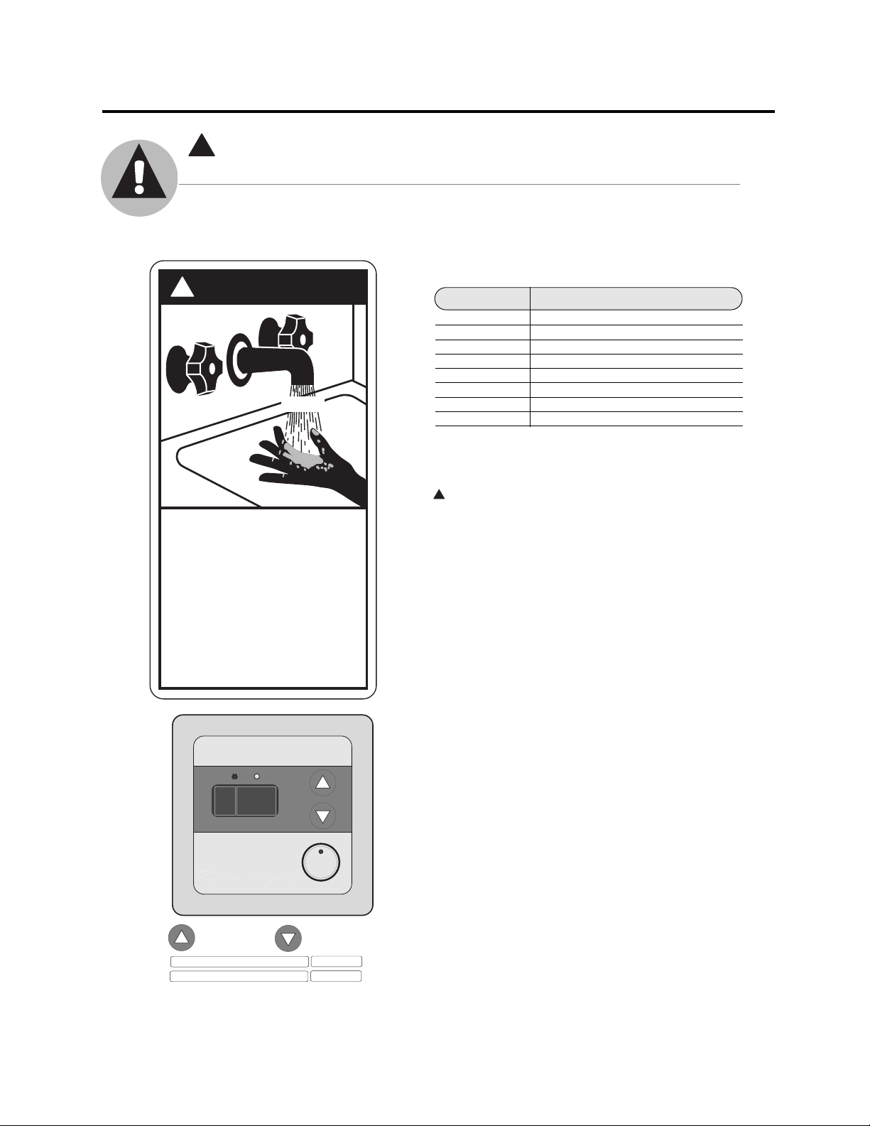
Time/Temperature Relationship in Scalds
Water Temperature Time To Produce a Serious Burn
120°F (49°C) More than 5 minutes
125°F (52°C) 11/2 to 2 minutes
130°F (54°C) About 30 seconds
135°F (57°C) About 10 seconds
140°F (60°C) Less than 5 seconds
145°F (63°C) Less than 3 seconds
150°F (66°C) About 11/2
seconds
155°F (68°C) About 1 second
Table courtesy of Shriners Burn Institute
The chart shown above may be used as a guide in
determining the proper water temperature for your home.
DANGER: Households with small children, disabled or
elderly persons may require a 120°F (49°C) or lower
temperature setting to prevent contact with “HOT” water.
Maximum water temperature occurs while burner is on.
To find water temperature being delivered, turn on a hot
water faucet and place a thermometer in the water stream
and read the thermometer. (See page 27 & 28 for more
details.)
The temperature of the water at the outlet of the water
heater can be regulated by setting the temperature on
Remote Control. The remote control was set at 100°F
(38°C) before it was shipped from the factory.
The diagram to the bottom left illustrates the Remote
Control and how to adjust the water temperature.
Notice: The factory setting allows operating temperatures
between 100°F (38°C) and 120°F (49°C). Temperatures
of up to 140°F (60°C) can be achieved with the MAIN
(UMC-117) remote control and a dip switch adjustment.
Only qualified service personnel should perform this
adjustment. Only factory authorized remote control(s)
should be used.
Notice: When this water heater is supplying general
purpose hot water requirements for use by individuals,
a thermostatically controlled mixing valve for reducing
point of use water temperature is recommended to reduce
the risk of scald injury. Contact a licensed plumber or the
local plumbing authority for further information.
DANGER!
WATER TEMPERATURE SETTING
Safety and energy conservation are factors to be considered when selecting the water
temperature setting of a water heater’s remote control. Water temperatures above
125°F (52°C) can cause severe burns or death from scalding. Be sure to read and follow
the warnings outlined on the label pictured below.
IMPORTANT SAFETY INFORMATION
READ ALL INSTRUCTIONS BEFORE USING.
* Temperatures above 120°F (49°C) can be achieved
by adjusting the dip switch. See page 35 for dip
switch adjustment.
Notice:
Display
shows
°F only.
4
!
!
DANGER
HOT
BURN
Water temperature over 125° F can
cause severe burns instantly or
death from scalds.
Children, disabled and elderly are
at highest risk of being scalded.
See instruction manual before
setting temperature at water
heater.
Feel water before bathing or
showering.
Temperature limiting valves are
available, see manual.
!
PRIORITY
Higher (Hotter) Lower (Cooler)
100 102 104 106 108 110 112 114 116 118 120* 125 130 135 140 °F
38 39 40 41 42 43 44 46 47 48 49* 52 54 57 60 °C
°F
POWER
ON/OFF
5
Both LP and natural gas have an odorant added to aid in detecting a gas leak. Some
people may not physically be able to smell or recognize this odorant. If you are unsure or
unfamiliar with the smell of LP or natural gas, ask the gas supplier. Other conditions, such as
“odorant fade”, which causes the odorant to diminish in intensity, can also hide or camouflage
a gas leak.
DANGER!
NATURAL GAS AND LIQUEFIED PETROLEUM MODELS
● Water heaters utilizing LP gas are different
from natural gas models. A natural gas
water heater will not function safely on LP
gas and vice versa.
● No attempt should ever be made to convert
the water heater from natural gas to LP
gas. To avoid possible equipment damage,
personal injury or fire, do not connect the
water heater to a fuel type not in
accordance with the unit data plate;
propane for propane units and natural gas
for natural gas units. These units are not
certified for any other fuel type.
● LP appliances should not be installed below
grade (for example, in a basement) if such
installation is prohibited by federal, state
and/or local laws, rules, regulations or
customs.
● Propane or LP gas must be used with great
caution. It is heavier than air and will
collect first in lower areas, making it hard
to detect at nose level.
● Before attempting to light the water heater,
make sure to look and smell for gas leaks.
Use a soapy solution to check all gas fittings
and connections. Bubbling at a connection
indicates a leak that must be corrected.
When smelling to detect a gas leak, be sure
to sniff near the floor also.
● Gas detectors are recommended in LP
and natural gas applications and their
installation should be in accordance with
the detector manufacturer’s
recommendations and/or local laws,
rules, regulations or customs.
● It is recommended that more than one
method, such as soapy solution, gas
detectors, etc., be used to detect leaks
in gas applications.
Notice: If a gas leak is present or suspected:
● Do not
attempt to find the cause yourself.
● Do not
try to light any appliance.
● Do not
touch any electrical switch.
● Do not
use any phone in your building.
● Leave the building immediately and make
sure your family and pets leave also.
● Leave the doors open for ventilation and
contact the gas supplier, a qualified service
agency or the fire department.
● Stay away from the building until the
service call has been made, the leak is
corrected and a qualified agency has
determined the area to be safe.
6
Have the installer show you the location of the gas shut-off valve and how to shut it off
if necessary. Turn off the manual shut-off valve if the water heater has been subjected
to overheating, fire, flood, physical damage or if the gas supply fails to shut off.
● Read this manual entirely before installing
or operating the water heater.
● Use this appliance only for its intended
purpose as described in this Use and Care
Manual.
● Be sure your appliance is properly installed
in accordance with local codes and the
provided installation instructions.
● Do not attempt to repair or replace any
part of your water heater unless it is
specifically recommended in this manual.
All other servicing should be referred to a
qualified technician.
SAFETY PRECAUTIONS
IMPORTANT SAFETY INFORMATION
READ ALL INSTRUCTIONS BEFORE USING.
WARNING!
For your safety, the information in this manual must be followed to minimize the risk
of fire or explosion, electric shock, or to prevent property damage, personal injury or
loss of life.
FOR INSTALLATIONS IN THE STATE OF CALIFORNIA
California Law requires that water heaters must be braced, anchored or strapped to resist
falling or horizontal displacement due to earthquake motions. For water heaters up to 52
gallon capacity, a brochure with generic earthquake bracing instructions can be obtained from:
Office of the State Architect, 1102 Q Street, Suite 5100, Sacramento, CA 95814 or you may call
916-445-8100 or ask a water heater dealer.
However, applicable local codes shall govern installation. For residential water heaters
of a capacity greater than 52 gallons or tankless-style, consult the local building jurisdiction
code for acceptable bracing procedures.
READ AND FOLLOW THIS SAFETY INFORMATION CAREFULLY.
SAVE THESE INSTRUCTIONS
!
Installing the (OUTDOOR) water heater:
This water heater must be installed in accordance with these instructions, local codes, utility company
requirements and/or in the absence of local codes, use the latest edition of the American National
Standard/National Fuel Gas Code. A copy can be purchased from either the American Gas Association, 400
North Capitol Street Northwest, Washington, DC 20001 as ANSI standard Z223.1 or National Fire Protection
Association, 1 Batterymarch Park, Quincy, MA 02269 as NFPA 54. In Canada, the latest edition of the CSA
B149.1 Natural Gas and Propane Installation, and the Canadian Electrical Code, CSA C22.1 Part 1, in the
absence of local codes.
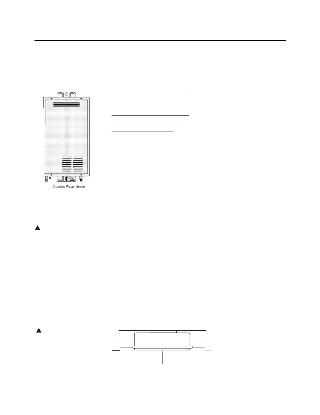
Location of the OUTDOOR
water heater
This water heater is for OUTDOOR
installation ONLY!
This water heater shown on the left is
an outdoor model and must be mounted
vertically. It must not be installed
indoors or in a confined space.
The water heater should be installed
close to the most frequently used outlet
and its position chosen with safety and
service in mind.
Make sure people (particular children,
disabled, and elderly) will not touch the
hot water outlet or the flue terminal.
The flue terminal and air inlet must be
clear of obstruction and shrubbery.
The water heater should not be located
in an area where leakage of the heat
exchanger or connections will result
in damage to the area adjacent to it
or to lower floors of the structure.
A gas fired water heater or any other
appliance should not be installed in
a space where liquids which give off
flammable vapors are to be used or stored.
Such liquids include gasoline, but are not
limited to, LP gas (butane or propane),
paint or adhesives and their thinners,
solvents or removers.
Because of natural air movement in a room
or other enclosed space, flammable vapors
can be carried some distance from where
their liquids are being used or stored. The
open flame of the water heater’s main
burner can ignite these vapors, causing an
explosion or fire which may result in
severe burns, death or property damage.
The water heater must be located so it is not
subject to physical damage, for example, by
moving vehicles, area flooding, etc.
● The water heater should be installed
vertically with the water, gas and power
connections on the underside pointing
toward the ground.
● Failure to properly install the water heater
outdoors as outlined in this manual can
result in unsafe operation.
● Hot and cold water lines should be insulated
to conserve water and energy.
● The water heater and water lines should
be protected from exposure to freezing
temperatures.
● Do not install water heater where subject
to vibrations.
● Do not install the water heater in
Recreational Vehicles, Mobile Homes,
Boats and other Watercrafts.
● Do not install the water heater near
vents for heating or cooling. A minimum
of 4 feet should be maintained.
● Minimum clearance from combustible
and noncombustible construction is
1/2” (1.3 cm) sides, 0” rear (with support
bracket); 12” (30 cm) from the bottom;
12” (30 cm) from the front of the water
heater; (24” [61 cm] from front
recommended for servicing purposes).
If the clearances stated on the Instruction/
Warning Label, located on the front panel
of the heater differ, install the water
heater according to the clearances stated
on the label.
WARNING: Combustible
construction refers to
adjacent walls and ceilings
and should not be confused
with combustible or
flammable products and
materials. Combustible
and/or flammable products
and materials should never
be stored in the vicinity of
this or any gas appliance.
Minimum Clearance from Combustible and
Non-Combustible Construction.
Top: Do not install this water
heater under an overhang less
than 36” (91 cm) from its top.
The area under the overhang
must be open on 3 sides.
7
CAUTION:
Protect plastic, paint or
other items sensitive to heat
using non-combustible
insulation if these are
exposed to the flue exhaust
even though they may be
more than 24” (61 cm) away
from the water heater.
!
!
min.
1/2 "
(1.3 cm)
Front = 12" (30 cm)
Back = 0" (with support bracket)
min.
1/2 "
(1.3 cm)
min. 12" (30 cm)
(24" (61 cm) minimum is
recommended for service)
Side = 1/2" (1.3 cm)
Bottom = 12" (30 cm)
WARNING: Follow vent
manufacturer’s instruction
while installing vent. If
required, provide additional
clearances from vent to
combustibles per vent
manufacturer’s instruction.
8
Installing the (INDOOR) water heater :
This water heater must be installed in accordance with these instructions, local codes, utility company
requirements and/or in the absence of local codes, use the latest edition of the American National
Standard/National Fuel Gas Code. A copy can be purchased from either the American Gas Association, 400
North Capitol Street Northwest, Washington, DC 20001 as ANSI standard Z223.1 or National Fire Protection
Association, 1 Batterymarch Park, Quincy, MA 02269 as NFPA 54. In Canada, the latest edition of the CSA
B149.1 Natural Gas and Propane Installation, and the Canadian Electrical Code, CSA C22.1 Part 1, in the
absence of local codes.
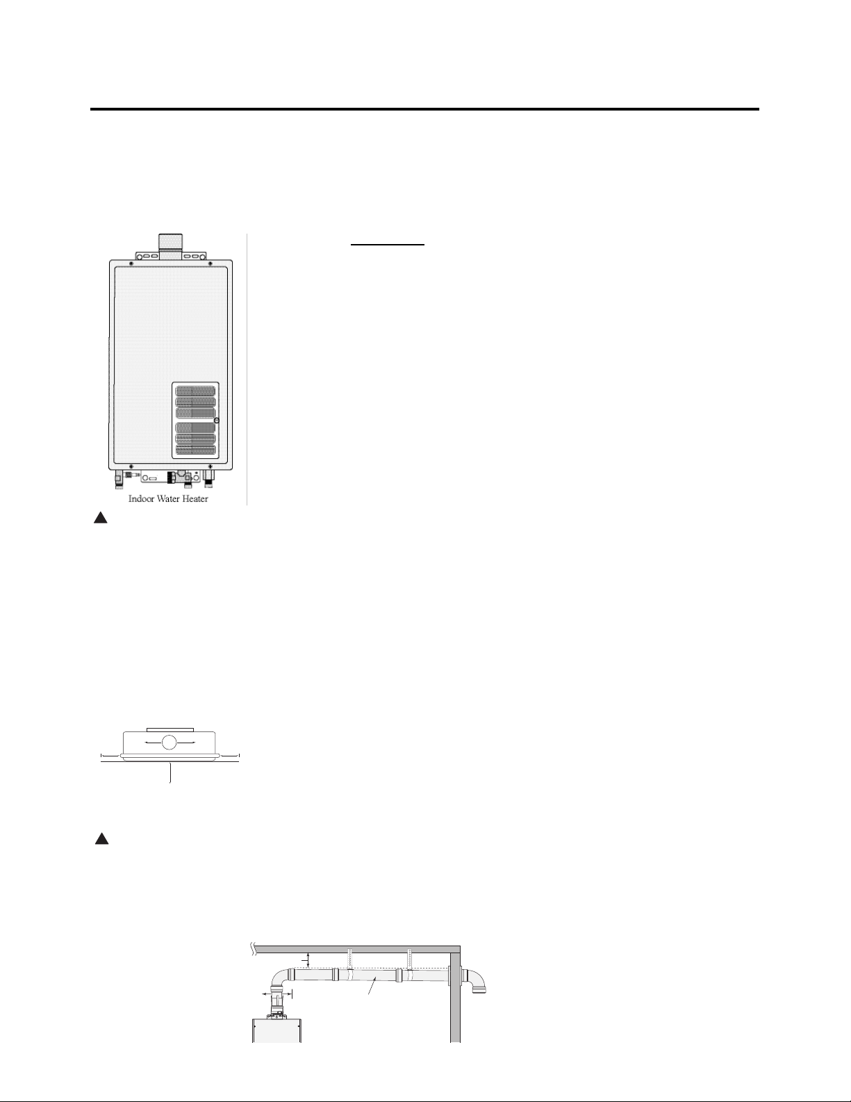
Location of INDOOR
Water Heater
This water heater is for INDOOR
installation ONLY!
The water heater should not be located in
an area where leakage of the heat exchanger
or connections will result in damage to the
area adjacent to it or to lower floors of the
structure.
When such areas cannot be avoided, it is
recommended that a suitable catch pan,
adequately drained, must be installed under
the water heater.
The pan must not restrict combustion
air flow.
A gas fired water heater or any other appliance
should not be installed in a space where
liquids which give off flammable vapors are
to be used or stored. Such liquids include
gasoline, LP gas (butane or propane), paint
or adhesives and their thinners, solvents
or removers.
Because of natural air movement in a room or
other enclosed space, flammable vapors can be
carried some distance from where their liquids
are being used or stored. The open flame of
the water heater’s main burner can ignite these
vapors causing an explosion or fire which may
result in severe burns, death or property
damage.
The water heater must be located so it is not
subject to physical damage, for example, by
moving vehicles, area flooding, etc.
If the water heater is installed in a garage, it
should be installed so that the direct ignition
system and main burner are no less than 18
inches (45 cm) above the garage floor.
Raising the gas fired water heater will reduce
BUT NOT eliminate the possibility of lighting
the vapor of any flammable liquids which may
be improperly stored or accidentally spilled.
● The water heater should be installed as
close as practical to the vent termination to
minimize vent length and the number of
elbows required for venting.
● The water heater should be installed with
the proper venting materials and termination
suitable for Category III venting.
● A fire stop plate should be installed at every
penetration of a floor or ceiling if the vent is
not running in a fire rated shaft.
● Failure to install and properly vent the water
heater to the outdoors as outlined
in the Venting Section of this manual
can result in unsafe operation.
● Long hot water lines should be insulated to
conserve water and energy.
● The water heater and water lines should
be protected from exposure to freezing
temperatures.
● Do not install the water heater in
bathrooms, bedrooms, any occupied rooms
normally kept closed, or in outdoor areas.
● Do not install the water heater in small,
poorly ventilated rooms, or in airtight
rooms with air conditioning.
● Do not install water heater where subject
to vibrations.
● Do not install the water heater in
Recreational Vehicles, Mobile Homes,
Boats and other Watercrafts.
● Do not install the water heater near vents
for heating or cooling. A minimum of 4
feet (1.2 m) should be maintained.
● Minimum clearance from combustible and
non-combustible construction is 1/2” (1.3
cm) sides, 0” rear (with support bracket);
12” (30 cm) from the bottom; 12” (30 cm)
from the front of the water heater; and 12”
(30 cm) from the top (24” [61 cm] from
front and top is recommended for servicing
purposes).
● Maintain a minimum clearance of 3” (8 cm)
around the vent pipe to combustible or noncombustible construction, unless otherwise
specified by vent manufacturer or installed
in an enclosed space. If the clearances
stated on the Instruction/Warning Label,
located on the front panel of the heater
differ, install the water heater according
to the clearances stated on the label.
See the back page of this manual for
additional requirements for the
Commonwealth of Massachusetts.
WARNING: Combustible
construction refers to
adjacent walls and ceilings
and should not be confused
with combustible or
flammable products and
materials. Combustible
and/or flammable products
and materials should never
be stored in the vicinity of
this or any gas appliance.
Minimum Clearance from
Combustible and
Non-Combustible
Construction.
!
(30 cm)
(1.3 cm)
(30 cm)
min.
1/2 "
(1.3 cm)
min.
1/2 "
(1.3 cm)
Top = 12" (30 cm)
Vent = 3"
Front = 12" (30 cm)
* (with support bracket)
!
(8 cm)
min. 3"
min. 3"
(8 cm)(8 cm)
min. 12"
(24" (61 cm) minimum is
recommended for service)
Back = 0" *
Side = 1/2"
Bottom = 12"
3” (8 cm)
3” (8 cm) min
min
3” (8 cm)
min
Vent
Pipe
L
Proper operation of the water heater requires air for combustion and ventilation. Provisions for
combustion and ventilation air must comply with referenced codes and standards.
Combustion and Ventilation Air (Indoor Water Heater Only)
NOTICE: If the water heater is installed in
an unconfined space within a building of
conventional frame, masonry or metal
construction, infiltration air is normally
adequate for proper combustion and
ventilation. If the water heater is installed in
a confined space, provisions for combustion
and ventilation air must be made.
A confined space is one having a volume
of less than 50 cubic feet (1.4 m3) per
1000 Btuh (0.3 kw) of the aggregate input
of all appliances within that space.
The air must be supplied through two
permanent openings of equal area. One
is to be located within 12” (30 cm) above
the floor and the other is to be located
within 12” (30 cm) below the ceiling.
The minimum net free area of each opening
must not be less than one square inch (6.5
cm2) per 1000 Btuh (0.3 kw) of the total
input rating of all the appliances in the
enclosure (but not less than 100 square
inches [650 cm2]) if each opening
communicates with other unconfined areas
inside the building. The above
requirements shall be used unless:
national, provincial, or local codes govern
the requirement for these air openings.
Buildings of unusually tight construction
shall have the combustion and ventilation
air supplied from outdoors, or a freely
ventilated attic or crawl space.
If air is supplied from outdoors, directly or
through vertical ducts, there must be two
openings located as specified above and
each must have a minimum net free area
of not less than one square inch
(6.5 cm
2
) per 4000 Btuh (1.2 kw) of the
total input rating of all the appliances in
the enclosure.
If horizontal ducts are used to
communicate with the outdoors, each
opening must have a minimum net free
area of not less than one square inch
(6.5 cm2) per 2000 Btuh (0.6 kw) of the
total input rating of all the appliances in
the enclosure. If ducts are used, the
minimum dimensions of rectangular air
ducts shall not be less than 3” (7.6 cm).
NOTICE: If the duct openings which supply
combustion and ventilation air are to be
covered with a protective screen or grille,
the net free area (openings in the material)
of the covering material must be used in
determining the size of the openings.
Protective screening for the openings MUST
NOT be smaller than 1/4” (0.64 cm) mesh to
prevent clogging by lint or other debris.
Corrosive Atmospheres
The air in beauty shops, dry cleaning
establishments, photo processing labs,
and storage areas for liquid and powdered
bleaches or swimming pool chemicals
often contains such halogenated
hydrocarbons.
An air supply containing halogenated
hydrocarbons may be safe to breathe,
but when it passes through a gas flame,
corrosive elements are released that
will shorten the life of any gas burning
appliance.
Propellants from common spray cans
or gas leaks from A/C and refrigeration
equipment are highly corrosive after
passing through a flame.
The water heater warranty is voided when
failure of the heater is due to operation in
a corrosive atmosphere.
NOTICE: The water heater
should not be installed near
an air supply containing
halogenated hydrocarbons.
DANGER: OUTDOOR
water heaters must not
be installed indoors or
in a confined space.
Install outdoor water
heaters outdoors only.
9
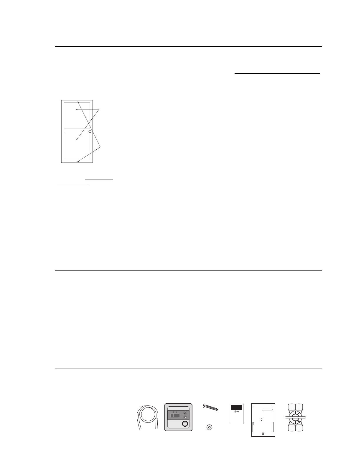
Inspect Shipment
Inspect the water heater for possible damage. Check the markings on the rating plate of
the water heater to be certain the type of gas supplied corresponds to the water heater
requirements. Verify all included parts are present (see below).
(Indoor models only)
Air openings
minimum 1 in
2
(6.5 cm2) per
1000 Btuh of
total input
Min. 3”
(7.6 cm)
Use & Care Manual
With Installation Instructions for the Installer
Residential Gas
Tankless
Water Heaters
Warning: This waterheateris not suitable for
use in manufactured (mobile) homes!
The purpose of this manual is twofold: one, to provide the installerwith
the basic directions and recommendations forthe properinstallation and
adjustment of the waterheater; and two, to the owner–operator, to
explain the features, operation, safety precautions, maintenance and
troubleshooting of the waterheater. This manual also includes a parts
list.
It is imperative that all persons who are expected to install, operate or
adjust this waterheaterread the instructions carefully so they may
understand how to perform these operations. If you don’t understand
these instructions orany terms within it, seek professional advice.
Any questions regarding the operation, maintenance, service or
warranty of this waterheatershould be directed to the sellerfrom whom
it was purchased. If additional information is required, referto the
section on How to Obtain Service Assistance.
Do not destroy this manual. Please read carefully and keep in a safe
place forfuture reference.
Recognize this symbol as an indication of Important Safety
!
Information!
California Proposition 65 Warning:This product contains
!
chemicals known to the State of California to cause cancer, birth
defects orotherreproductive harm.
WARNING: If the information in these instructions is not followed exactly,
!
a fire orexplosion may result causing property damage, personal injury ordeath.
!
FOR YOUR SAFETY!
● If you cannot reach yourgas supplier, call
—Do not store or use gasoline or other
the fire department.
flammable vapors or liquids or other
combustible materials in the vicinity of this or
● Do not return to yourhome until authorized
any otherappliance. To do so may result in an
by the gas supplierorfire department.
explosion orfire.
— Improperinstallation, adjustment,
alteration, service ormaintenance can cause
—WHATTO DO IFYOU SMELL GAS
property damage, personal injury, ordeath .
●Do not try to light any appliance.
Referto this manual. Installation and service
● Do not touch any electrical switch; do not
must be performed by a qualified installer,
use any phone in yourbuilding.
service agency orthe gas supplier.
● Immediately call yourgas supplierfrom a
neighbor’s phone. Follow the gas
supplier’s instructions.
I
S
G
E
N
D
Printed in USA
Tankless Unit
C
E
D
R
E
I
T
F
I
®
Use & Care Manual
Manual Appliance
Gas Shut-off Valve
Drain Tubing
PRIORITY
°F
POWER
ON/OFF
Remote Control
Assembly Kit
Wood Screw x 5pcs.
Washer x 4 pcs.
detimiL
ytnarraW
®
TAW
SELK
MMO
NAT LAICRE
C
SRETAEH RETAW SAG
CXE TAEH RAEY 3 A HTIW
IMIL STRAP RAEY 1
RAW DET
Warranty
fo etacifitreC
AICREMMOC
SRETAEH RE
S
DNA REGNAH
YTNAR
)
( 1-78431PA
50/30
10
Installing the (INDOOR) water heater:
The water heater must be installed with a 3” diameter UL approved Category III Stainless Steel appliance
vent pipe and an appropriate adapter.
Venting
The installation of venting must comply
with national codes, local codes and the
vent manufacturer’s instructions.
The water heater must be vented to the
outdoors as described in these instructions.
DO NOT connect this water heater to a
chimney. It must be vented separately from
all other appliances.
All vent components (adapters, pipe, elbows,
terminals, etc.) should be UL 1738 Certified
Stainless Steel Venting Material
(e.g. AL29-4C).
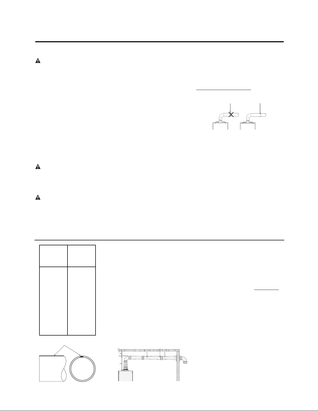
The specified vent termination must be used.
The termination should be a 90° elbow with
screen. (Refer to pages 14 and 15 for an
example of 90° termination)
Use a vent pipe with an anti-disconnection
joint.
The use of a High Temperature Silicone
(500°F [260°C]) may be required to seal
vent connections. To prevent accidental gas
exhaust leakage, apply a 1/4” (6 mm) wide
bead approximately 1/4” (6 mm) from the
end and another bead against the joint side
of the stop bead.
Follow vent manufacturer’s installation
instructions and their recommended
clearances to combustibles.
The unit can be vented either horizontally
or vertically.
Vent pipe runs must be adequately supported
along both horizontal and vertical runs.
The maximum recommended unsupported
span should be no more than five (5) feet
(1.5 m). Support isolation hanging bands
should be used. DO NOT use wire. (See
diagram below).
Notes on pr
e-existing v
ent:
If the water heater is being installed as a
replacement for an existing water heater, a
thorough inspection of the existing venting
system must be performed prior to any
installation work. Verify that the correct
materials, vent lengths and terminal locations
as detailed in this Use and Care Manual have
been met. Carefully inspect the entire
venting system for any signs of cracks or
fractures, particularly at the joints between
elbows or other fittings and the straight runs
of vent pipe. Check the system for signs of
sagging or other stresses in the joints as a
result of misalignment of any components in
the system. If any of these conditions are
found, they must be corrected in accordance
with the venting instructions in this manual
before completing the installation and
putting the water heater into service.
Additional installatio information for The
Commonwealth of Massachusetts is located
on the back page of this manual.
DANGER: Failure to
install the appliance vent
adapter and properly vent
the water heater to the
outdoors as outlined in the
Venting section of this
manual will result in unsafe
operation of the water
heater, causing death,
serious injury, explosion,
or fire. To avoid the risk
of fire, explosion, or
asphyxiation from carbon
monoxide, NEVER operate
the water heater unless it is
properly vented and has
adequate air supply for
proper operation as
outlined in the Venting
section of this manual.
WARNING: Use 3”
UL approved Category III
Stainless Steel vent
material only. No other
vent material is permitted.
WARNING: Refer to
page 8 for clearances to
combustible material.
Venting Lengths
MAXIMUM VENT LENGTH: The
system will not operate if there is excessive
restriction (pressure drop) in the venting
system. A maximum 34’ 6”
(10.5 m)
of vent
pipe may be used provided there is only one
90° elbow in the system. If additional elbows
are required: two elbows can be used with 33’
(10.0 m)
, three elbows can be used with
31’
6” (9.5 m)
or four elbows can be used with
30’(9.2 m) of vent pipe.
A 90° elbow is equivalent to 1’6” (45cm) to
straight pipe. A 45° elbow is equivalent to 9”
(22 cm) of straight pipe.
The termination elbow does not count as an
elbow when determining total vent lengths.
The vent can be installed with a slight
downward slope of 1/4” per foot of
horizontal run toward the vent terminal (see
diagram below). This ensures that any
condensate formed during operation of the
unit is evacuated from the appliance.
A 1/4” per foot upward slope is acceptable
when it is not possible to vent with a
downward slope; however, a UL approved
Category III Stainless Steel condensate trap
MUST be installed at the beginning of the
horizontal run. (See page 14 “Example B:
Typical Horizontal Termination w/ 1/4” per
foot UPWARD Slope” or page 15, “Standard
Vertical Vent Termination” for examples).
MINIMUM VENT LENGTH: The venting
may be as short as 12” (30 cm), provided
one vent termination is installed to the
outdoors through a sidewall, one 90° elbow
is included in the installation and the wall
thimble is installed.
Notice: Make sure that the seam of the vent
pipe in horizontal runs is toward the top of
the installation (see diagram to the far left).
Min. 3"
(8 cm)
Max. 2 feet
(61 cm)
1/4" per foot
downward slope
Number of
90° elbows
(bends)
Maximum
Length of
Straight Pipe
1
2
3
4
34’ 6”
(10.5 m)
33’
(10.0 m)
31’ 6”
(9.5 m)
30’ 0”
(9.2 m)
NO! YES!
Vent Seam
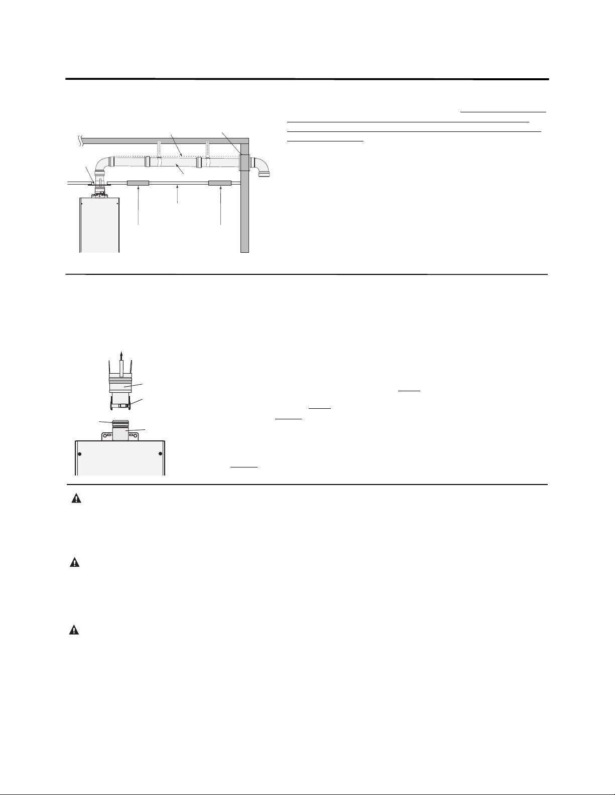
Venting Through Closed Spaces
If the vent piping passes through a closed space, a minimum clearance of
8” (20 cm) when installed horizontally or 6”
(15 cm)
when installed
vertically should be maintained between the vent pipe and combustibles
and noncombustibles. Be sure to follow local codes and vent
manufacturer’s installation instructions.
For maintenance and inspection purposes, the following access panels are
required.
● Two (2) inspection access panels large enough to allow access for
venting inspection. One (1) of these access panels should be close
to where the vent pipe enters the ceiling. The other access panel
should be near the vent termination.
● A ventilation access panel with a 16 in2(103 cm2) opening should
be provided every 10 ft (3 m).
/
Fire
Appliance Vent Adapter
The water heater must be installed
with a UL 1738 approved Category III
Stainless Steel appliance vent adapter.
Read the following instructions before
installation.
● Test fit the adapter over the water heater
collar before proceeding. Adjust clamp as
needed.
● With an alcohol wipe, clean inside
surface
“A” of adapter and outside surface “B” of
heater collar.
● Apply 1/4” (6 mm) wide bead of high
temperature silicone (500°F [260°C])
around outside
of heater collar “B”.
● Slide adapter end “A” down over heater
collar “B” as far as it will go.
● Tighten the clamp around the collar.
● Inspect the inside of the adapter to verify
that the collar and adapter are sealed. If
more sealant is required, apply sealant to a
flat tool, then spread around the collar edge
on inside
of adapter.
● Ensure that the clamp does not interfere
with the damper shaft.
NOTICE: Follow the appliance vent adapter
manufacturer’s instructions.
Draining the Condensate
Provision should be made to collect and
dispose of condensate from venting systems.
When a water heater is vented horizontally,
the vent pipe can have a DOWNWARD or
UPWARD slope towards the termination. If
an UPWARD slope is used, a condensate trap
must be installed as close as practical to the
water heater in order to prevent condensate
from draining back into the water heater. See
Examples A and B on page 14 for
DOWNWARD and UPWARD slope for
horizontally vented water heaters.
When a water heater is vented vertically, an
UPWARD slope must always be used. A
condensate trap must be installed in the
horizontal section of the vent and as close
as practical to the water heater in order to
prevent condensate from draining back into
the water heater. See the diagram on page 15
showing UPWARD slope for vertically
vented water heaters.
Always attach a drain hose to the drain fitting
and plumb the hose to a sanitary sewer drain.
A high temperature silicone tubing suitable for
use with acidic condensate and appropriate for
the temperature range should be used.
The drain tube is fashioned into a “pigtail” trap
and must be filled with water to prevent flue
gases from emitting into the building prior to
operating the appliance.
CAUTION: Condensate
must drain away from the
water heater and should
not be allowed to drain
back into any part of the
vent system.
WARNING: Failure to
provide a vent condensate
drain close to the appliance
could allow acidic flue gas
condensate to enter into
appliance flueways, causing
premature failure of the
appliance.
CAUTION: Condensate
is known to be acidic; refer
to local, state (provincial)
or federal codes for proper
handling and discharge
methods.
11
CAUTION: Ensure that the
appliance vent adapter is
securely attached to the
water heater collar.
Stop
4" per foot
1
downward slope
Inspection
Access Panel #1
Ceiling
Board
Vent Pipe
Inspection
Wall Thimble
Access
Panel #2
Exhaust
Flow
Appliance
Vent Adapter
Clamp
A
High Temp.
Sealant
Water Heater
Collar
B
 Loading...