


Gas Fireplaces
P36 - P36D Gas Fireplace
P36 - P36D Zero Clearance Direct Vent Gas Fireplace
Model |
P36-NG4 |
P36-LP4 |
P36D-NG1 |
|
P36D-LP1 |
||
Fuel Type |
Natural Gas |
Propane |
Natural Gas |
|
Propane |
||
|
|
|
|
|
|
|
|
Minimum Supply |
5” W.C. |
12” W.C. |
5” W.C. |
|
12” W.C. |
||
Pressure |
(1.25 kPa) |
(3.00 kPa) |
(1.25 kPa) |
|
(3.00 kPa) |
||
|
|
|
|
|
|
|
|
Manifold |
3.8” W.C. |
11” W.C. |
3.8” W.C. |
|
11” W.C. |
||
Pressure - High |
(0.95 kPa) |
(2.74 kPa) |
(0.95 kPa) |
|
(2.74 kPa) |
||
|
|
|
|
|
|
|
|
Manifold |
1.1” W.C. |
2.9” W.C. |
1.1” W.C. |
|
2.9” W.C. |
||
Pressure - Low |
(0.27 kPa) |
(0.72 kPa) |
(0.27 kPa) |
|
(0.72 kPa) |
||
|
|
|
|
|
|
|
|
Orifi ce Size |
#37 DMS |
#52 DMS |
#37 DMS |
|
#52 DMS |
||
|
|
|
|
|
|
|
|
Minimum Input |
15,500 BTU/h |
15,000 BTU/h |
15,500 BTU/h |
|
15,000 BTU/h |
||
(4.54 kW) |
(3.96 kW) |
(4.54 kW) |
|
(3.96 kW) |
|||
|
|
||||||
|
|
|
|
|
|
|
|
Maximum Input |
30,000 BTU/h |
30,000 BTU/h |
30,000 BTU/h |
|
30,000 BTU/h |
||
(8.79 kW) |
(8.79 kW) |
(8.79 kW) |
|
(8.79 kW) |
|||
|
|
||||||
|
|
|
|
|
|
|
|
Vent Sizing |
4” Inner / 6 5/8” |
4” Inner / 6 5/8” |
4” Inner / 6 5/8” |
|
4” Inner / 6 5/8” |
||
Outer |
|
Outer |
Outer |
|
Outer |
||
|
|
|
|||||
|
|
|
|
|
|
|
|
|
|
|
|
||||
|
Approved Venting Systems |
|
|||||
|
Flex Vent Systems: |
|
FPI AstroCap™ Flex Vent |
|
|||
Rigid Pipe Vent Systems: |
|
Simpson Dura-Vent® Direct Vent GS |
|||||
|
|
|
|
American Metal Products Ameri Vent |
|||
|
|
|
|
Security Secure Vent® |
|
||
|
|
|
|
Selkirk Direct-Temp. |
|
||
B
L
A
C |
D |
|
F |
||
|
|
|
|
|
|
|
|
|
E |
|
|
|
|
|
|
A |
|
|
|
|
|
|||||
|
|
|
|
|
|
|
|
|||||
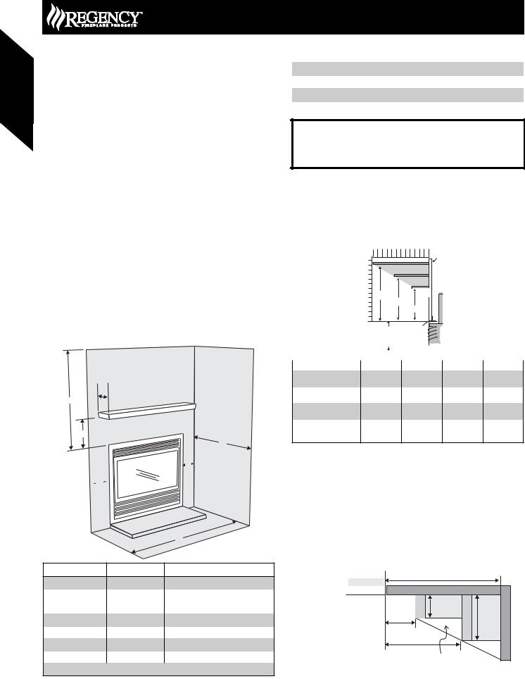
Unit Dimensions |
Description |
P36 |
|
|
P36D |
|||||||
|
|
|
|
|
|
|
|
|||||
A |
Front Face Width |
36” (914mm) |
|
|
|
36” (914mm) |
||||||
B |
Rear Firebox Width |
33-1/4” (838mm) |
|
33-1/4” (838mm) |
||||||||
C |
Front Face Height |
30-1/2” (775mm) |
|
30-1/2” (775mm) |
||||||||
D |
Height w/ Standoff |
36” (914mm) |
|
|
37” (940mm) |
|||||||
E |
Unit Depth |
12-3/4” (324mm) |
|
17-1/8” (435mm) |
||||||||
F |
Height to Vent |
32-1/2” (826mm) |
|
32-1/2” (826mm) |
||||||||
|
|
|
|
|
|
|
|
|||||
Framing Dimensions |
Description |
P36 |
|
|
|
P36D |
||||||
|
|
|
|
|
|
|
|
|||||
G |
Framing Width* |
36-1/4” (921mm) |
|
|
36-1/4” (921mm) |
|||||||
H*** |
Framing Height* *** |
36-1/4” (921mm)*** |
|
37-1/4” (946mm)*** |
||||||||
I |
Framing Depth* |
12-3/4” (324mm) |
|
17-1/8” (435mm) |
||||||||
J |
Corner Wall Length |
42-7/16” (1078mm) |
|
|
48” (1219mm) |
|||||||
K |
Corner Facing Wall |
60” (1524mm) |
|
|
|
68” (1727mm) |
||||||
Width |
|
|
||||||||||
|
|
|
|
|
|
|
|
|
|
|||
L |
Framed Chase Ceiling |
46” (1168mm) |
|
46-1/2” (1181mm) |
||||||||
M |
Vent Centerline Height |
40-1/2” (1029mm) |
|
40-1/2” (1029mm) |
||||||||
N |
Gas Connection Height |
2” (51mm) |
|
|
2” (51mm) |
|||||||
O |
Gas Connection Inset |
3-1/2” (89mm) |
|
|
3-1/2” (89mm) |
|||||||
P |
Gas Connection Width |
4” (102mm) |
|
|
4” (102mm) |
|||||||
|
|
|
|
|
|
|
|
|
|
|
|
|
***Important: Framing height requires consideration of the hearth depth. Dimension H = H + the thickness of installed hearth.
|
|
Top Header |
|
|
Drywall |
|
|
|
(or other |
|
|
H |
facing) |
|
|
|
|
||
|
|
10" (254mm) |
|
|
|
dia. Hole through |
|
|
|
wall Vent. |
|
G |
I |
|
|
|
|
||
|
|
M |
|
|
J |
|
|
|
N |
|
|
K |
O |
P |
|
Opening for gas |
|||
|
|||
|
connection |
||
*If using the Barcelona Surround, Kensington, Balmoral, or Tripoli Screen Door please note that framing and facing must be non combustible (12” on top and 6” on both sides) and that the Barcelona is only approved for installation with a single sidewall.
Please refer to Page 11 (Exterior Vent Terminations) for additional guidelines on vent locations.
June 2007 Regency Product Specifications Book |
35 |
Fireplaces Gas
Gas Fireplaces
Gas Fireplaces
P36 - P36D Gas Fireplace
Framing and Finishing
1)Determine the total thickness of facing material (e.g. drywall plus ceramic tiles) to allow the fi nished surface to be fl ush with the front of the unit. Total facing thickness can vary from 1/2” (13mm) to
1-1/4” (32mm) thick.
2)Frame in the enclosure for the unit with framing material.
Note: Header for the P36 must be installed vertically to maintain clearances to combustible materials. Non combustible header may be installed horizontally.
3)For exterior walls, insulate the enclosure to the same degree as the rest of the house, apply vapor barrier and drywall, as per local installation codes. (Do not insulate the fireplace itself.)
4)The top of the unit must not be closer than 32” (813mm) to the ceiling.
5)Combustible material may be brought up to the top and sides of the unit and be covered with ceramic tiles, bricks, rock or other suitable combustible fi nishing materials.
If using the Barcelona Surround, Kensington, Balmoral, or Tripoli Screen Door please note that framing and facing must be non combustible (12” on top and 6” on both sides) and that the Barcelona is only approved for installation with a single sidewall.
Note: The unit does not have to be completely enclosed in a chase. The clearance on top of the unit is 0” to the standoffs so combustible building materials can be laid directly on top of the standoffs. You must maintain proper clearances from the vent to combustible materials (See Below).
6)Use metal studs for framing where the minimum clearance from the vent to combustible material cannot be maintained.
Clearance Requirements
D
 B
B 
Vent Clearances |
Clearance Dimension |
Horizontal - Top |
2” (51mm) |
Horizontal - Side |
1-1/2” (38mm) |
Horizontal - Bottom |
1-1/2” (38mm) |
Vertical (Flex or Rigid) |
1-1/4” (32mm) |
WARNING
Failure to maintain required clearances is a major cause of chimney related fires. Installation of this fireplace must comply with these clearances.
Combustible Mantels
Because of the extreme heat this fireplace emits, the mantel clearances are critical. Combustible mantel clearances from top of the louvers are shown in the diagram below. Mantel may be installed anywhere in the shaded area or higher.
|
Mantel Clearances |
|
|
||||
12 |
10 |
8 |
6 |
4 |
2 |
0 |
|
|
|
12" (305mm) |
|
|
Drywall |
||
|
|
|
|
|
|||
|
|
|
7-1/2"(191mm) |
Standoff |
|||
|
|
|
3-1/2" (89mm) |
||||
|
B |
|
C |
|
|
|
|
|
|
|
D |
|
|
|
|
|
|
|
|
|
|
|
|
0 |
|
|
|
|
|
|
|
|
A |
Top of |
|
|
|
|
Unit |
|
|
||
|
To base |
|
|
|
|
|
of Unit |
|
|
|
|
|
|
Side View |
|
||
|
|
|
|
|
|
Mantel Clearances |
A |
B |
C |
D |
|
with Flush Glass or |
30-1/2” |
14” (356mm) |
10” (254mm) |
7” (178mm) |
|
Hampton Cast |
(778mm) |
||||
|
|
|
|||
with Bay Option |
30-1/2” |
13” (330mm) |
10” (254mm) |
7” (178mm) |
|
(778mm) |
|||||
|
|
|
|
||
with Flush Glass and |
30-1/2” |
17” (432mm) |
12” (305mm) |
8” (203mm) |
|
Barcelona Surround |
(778mm) |
||||
|
|
|
|||
with Tripoli Screen Door,
30-1/2”
Kensington, or Balmoral 20” (508mm) N/A 12” (305mm) (778mm)
Front
Note: If desired a non-combustible mantel may be installed at a lower height.
Note: Ensure the paint that is used on the mantel and the facing is “heat resistant” or the paint may discolour.
Mantel Leg Clearances
Combustible mantel leg clearances as per diagram below:
Clearances are from the fi nished edge of the unit or an installed front.
Clearance: |
Dimension |
Measured From: |
|
|
6" Side Wall |
|
|
|
|
|
|
|
8" Single Sidewall when using the Barcelona Surrround |
||||
A: Mantel Height |
7” (178mm) |
Minimum (Additional on this page) |
P36 - P36D |
|
|
|
|
|
B: Sidewall |
6” (152mm) |
Side of installed front |
|
Mantelleg |
1-1/2" |
Mantelleg |
|
|
Sidewall: Barcelona Only |
8” (203mm) |
Approved for single sidewall only |
Maximum |
|
||||
C: Ceiling |
32” (813mm) |
Top of installed unit |
1-1/2” projection at 2” |
3" |
||||
minimum clearance. |
||||||||
D: Mantel Depth |
12” (305mm) |
Maximum (Additional on this page) |
2" |
|
|
|
||
|
|
|
|
|||||
|
|
|
|
|
||||
E: Alcove Width |
48” (1219mm) |
Sidewall to Sidewall (Minimum) |
|
5" |
|
|
||
|
|
|
|
|
|
|||
F: Alcove Depth |
36” (914mm) |
Front to back wall (Maximum) |
|
Allowable mantel leg |
|
|||
Top of Hearth must not be higher than the base of the fi rebox. |
|
|
projection. |
|
|
|||
|
|
|
|
|
||||
36 |
June 2007 Regency Product Specifications Book |
Gas Fireplaces
FPI Direct Vent System (Flex)
Horizontal Terminations Only
These venting systems, in combination with the P36 / P36D Direct Vent GasFireplace,havebeentestedandlistedasadirectventheatersystem by Warnock Hersey. The location of the termination cap must conform to the requirements in the Vent Terminal Locations diagram.
FPI Direct Vent (Flex) System Termination Kits include all the parts needed to install the P36 / P36D using a flexible vent.
FPI Kit # |
Length |
Contains: |
||
#946-515 |
4 Feet |
1) |
6-5/8” fl exible liner (Kit length) |
|
|
|
2) |
4” fl exible liner (Kit length) |
|
|
|
3) |
spring spacers (3) |
|
|
|
4) |
thimble (2) |
|
|
|
5) |
AstroCap termination cap (1) |
|
#946-516 |
10 Feet |
|||
6) |
screws (12) |
|||
|
|
7) |
tube of Mill Pac (1) |
|
|
|
8) |
plated screws (8) |
|
|
|
9) |
S.S. screws #8 x 1-1/2” drill point, (4) |
|
Notes:
1)Liner sections should be continuous without any joints or seams.
2)Only Flex pipe purchased from Regency may be used for Flex installations.
3)Horizontal sections must be supported every 3 feet.
Wall Thimble (2 pc)
4" (102mm) |
AstroCap |
dia. flue pipe |
Termination Cap |
6-7/8" |
Part #946-523/P |
|
(173mm) dia. |
spring |
Alternate Horizontal |
Flue pipe |
spacer |
Termination Caps |
|
Alternate:
Horizontal
Riser Vent
Terminal
Part# 640-530/P
P36 - P36D Gas Fireplace
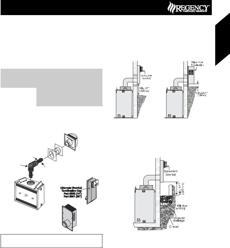
Snorkel Terminations
Snorkel Terminations:
For installations requiring a vertical rise on the exterior of the building,
14-inch and 36-inch tall Snorkel Terminations and the Riser Vent are available. Follow the same installation procedures as used for standard Horizontal Termination. NEVER install the snorkel upside down.
Below Grade Snorkel Installation (Dura-Vent Only)
If the Snorkel Termination must be installed below grade, i.e. basement application, proper drainage must be provided to prevent water from entering the Snorkel Termination. Refer to Rigid Pipe Installation instructions for details. Do not attempt to enclose the Snorkel within the wall, or any other type of enclosure.
If required by the external termination location the listed alternate termination caps may be used. (Refer to Page 11)
June 2007 Regency Product Specifications Book |
37 |
Fireplaces Gas
 Loading...