


www.regency-fire.com |
Freestanding Woodstove |
Owners & |
Installation Manual |
Tested by:
918-154b
MODELS: F2400M S2400M
Installer: Please complete the details on the back cover and leave this manual with the homeowner.
Homeowner: Please keep these instructions for future reference.
FPI FIREPLACE PRODUCTS INTERNATIONAL LTD. 6988 Venture St., Delta, BC Canada, V4G 1H4 |
02/18/08 |
Thank-you for purchasing a
REGENCY FIREPLACE PRODUCT.
The pride of workmanship that goes into each of our products will give you years of trouble-free enjoyment. Should you have any questions about your product that are not covered in this manual, please contact the REGENCY DEALER in your area.
Keep those REGENCY FIRES burning.
SAFETY NOTE: If this woodstove is not properly installed, a house fi re may result. For your safety, follow the installation instructions, contact local building, fi re offi cials, or authority having jurisdiction about restrictions and installation inspection requirements in your area.
The authority having jurisdiction should be consulted before installation to determine the need to obtain a permit.
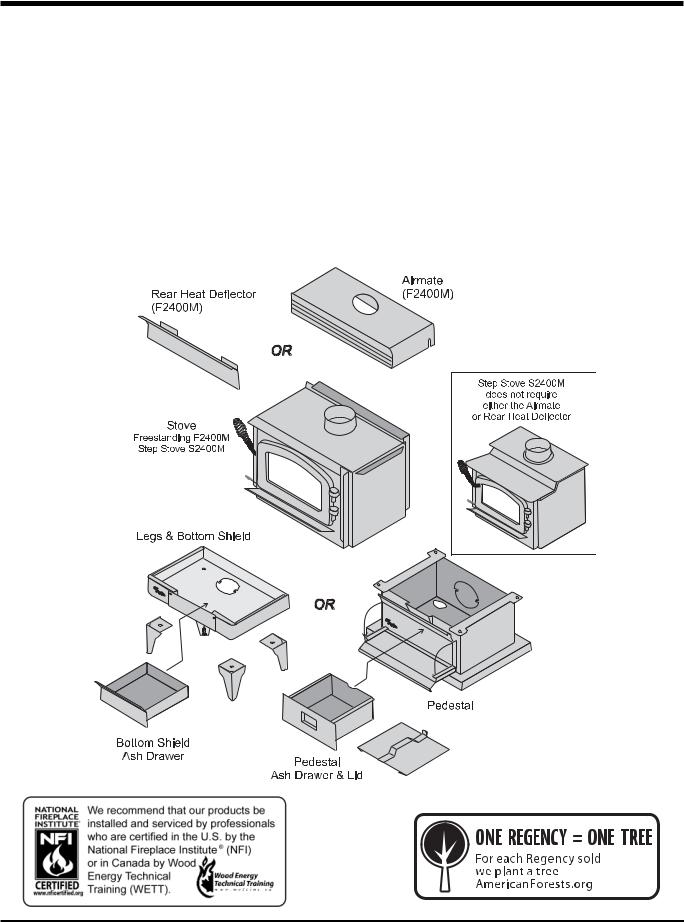
Modular Parts
2 |
Regency Freestanding Woodstove |

TABLE OF CONTENTS
SAFETY LABEL |
MAINTENANCE |
Safety Label for F2400 .................................................. |
4 |
Safety Label for S2400.................................................. |
5 |
INSTALLATION |
|
Unit Dimensions ............................................................ |
6 |
Residential Installation .................................................. |
7 |
Modular Installation Options.......................................... |
7 |
Room Air ....................................................................... |
8 |
Important ....................................................................... |
8 |
Minimum Clearance to Combustible Materials.............. |
8 |
Stove Assembly Prior to Installation ............................ |
10 |
Step-by-Step Chimney and Connector Installation ..... |
11 |
Masonry Chimney ....................................................... |
12 |
Masonry Fireplace....................................................... |
12 |
Factory Built Chimney ................................................. |
12 |
Combustible Wall Chimney |
|
Connector Pass-Throughs .......................................... |
13 |
Recommended Heights For Woodstove Flue.............. |
14 |
Mobile Home Installation ............................................. |
15 |
Listed Components For Mobile Home Installation....... |
16 |
Flue Baffl e &Secondary Air Tube Installation .............. |
16 |
Brick Installation .......................................................... |
17 |
Door Handle ................................................................ |
17 |
Glass Installation ......................................................... |
17 |
Step-by-Step Optional Accessories Installation........... |
17 |
Screen Door ................................................................ |
17 |
OPERATING INSTRUCTIONS |
|
Operating Instructions ................................................. |
19 |
Draft Control ................................................................ |
19 |
First Fire ...................................................................... |
19 |
Fan Operation ............................................................. |
20 |
Ash Disposal ............................................................... |
20 |
Safety Guidelines and Warnings ................................. |
20 |
Maintenance................................................................ |
21 |
Creosote...................................................................... |
21 |
Maintenance of Gold-plated Doors.............................. |
21 |
Latch Adjustment......................................................... |
21 |
Door Gasket ................................................................ |
21 |
Glass Maintenance...................................................... |
21 |
Wood Storage.............................................................. |
21 |
PARTS LIST |
|
F2400 Stove Main Assembly....................................... |
22 |
S2400 Step Stove Main Assembly .............................. |
23 |
Pedestal, Bottom Shield & Leg Options ...................... |
24 |
Firebrick....................................................................... |
25 |
WARRANTY |
|
Warranty ...................................................................... |
27 |
Regency Freestanding Woodstove |
3 |

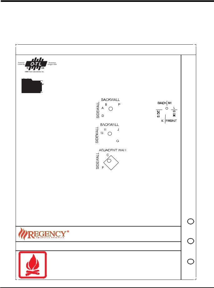
SAFETY LABEL
Thisisacopyofthelabelthataccompanieseach
Regency Freestanding Woodstove (F2400M).
We have printed a copy of the contents here for your review.
NOTE: Regency units are constantly being improved. Check the label on the unit and if there is a difference, the label on the unit is the correct one.
SAFETY LABEL FOR F2400M
|
|
|
|
|
|
|
|
|
|
|
|
|
|
|
|
|
|
244 |
|
|
|
|
|
|
|
|
|
|
|
|
|
|
|
|
|
|
|
|
|
|
|
|
|
|
|
|
|
|
|
|
|
|
|
|
|
|
|
|
|
|
|
|
|
|
|
|
|
|
|
|
|
|
|||||||||
|
|
|
|
|
|
|
|
|
|
|
LISTED SPACE HEATER, SOLID FUEL TYPE, ALSO |
|
DO NOT REMOVE THIS LABEL |
|||||||||||||||||||||||||||
|
|
|
|
|
|
|
|
|
|
|
SUITABLE FOR MOBILE HOME INSTALLATION |
|
|
|
|
|
|
|
|
|
|
|
|
|
|
|
|
|
|
|
|
|
|
|
|
|||||
|
|
|
|
|
|
|
|
|
|
|
|
244 |
|
|
|
|
|
|
|
|
|
|
|
|
|
|
|
|
|
|
|
|
|
|
||||||
|
|
|
|
|
|
|
|
|
|
|
|
|
|
|
|
|
|
|
|
|
|
|
|
|
|
|
|
|
|
|
|
|
|
|
|
|
|
|
|
|
|
|
|
|
|
|
|
|
|
|
|
|
|
|
|
|
|
|
|
|
|
|
|
|
|
|
|
|
|
|
|
|
|
|
|
|
|
|
|||
|
|
|
|
|
|
|
|
|
|
|
MODEL: REGENCY MEDIUM FREESTANDING STOVE - F2400M |
|||||||||||||||||||||||||||||
|
|
|
|
|
|
|
|
|
|
|
TESTED TO: |
UL-1482 / ULC-S627-00 / UL-737 |
REPORT NO:219-S-02-2 |
|||||||||||||||||||||||||||
|
|
|
|
|
|
|
|
|
|
|
THE F2400M MEETS UL737 STANDARD FOR FIREPLACE STOVES WHEN A FIRESCREEN IS PROVIDED. |
|||||||||||||||||||||||||||||
|
|
|
|
|
|
|
|
|
|
|
|
|
INSTALLAND USE ONLYINACCORDANCE WITH THE MANUFACTURER'S INSTALLATIONAND OPERATING |
|||||||||||||||||||||||||||
|
|
|
|
|
|
|
|
|
|
|
|
|
||||||||||||||||||||||||||||
|
|
|
|
|
|
|
|
|
|
|
|
|
INSTRUCTIONS. CONTACT LOCAL BUILDING OR FIRE OFFICIALS ABOUT RESTRICTIONS AND |
|||||||||||||||||||||||||||
|
|
|
|
|
|
|
|
|
|
|
|
|
INSTALLATION INSPECTION IN YOUR AREA. USE 150 MM (6 IN.) DIAMETER MINIMUM 24 MSG BLACK |
|||||||||||||||||||||||||||
|
|
|
|
|
|
|
|
|
|
|
|
|
OR 26 MSG BLUED STEEL CONNECTOR WITH LISTED UL103 HT FACTORY-BUILT CHIMNEY SUITABLE |
|||||||||||||||||||||||||||
|
|
|
|
|
|
|
|
|
|
|
|
|
FOR USE WITH SOLID FUELS OR MASONRY CHIMNEY. |
|
|
|
|
|
|
|
|
|
|
|
|
|
|
|
|
|
|
|
|
|
|
|
|
|||
|
|
|
|
|
|
|
|
|
|
|
|
|
SEE LOCAL BUILDING CODE AND MANUFACTURER'S INSTRUCTIONS |
|||||||||||||||||||||||||||
F2400M WITH |
F2400M WITHOUT |
FOR PRECAUTIONS REQUIRED FOR PASSING A CHIMNEY THROUGH A |
|
|
|
|
|
|
|
|
|
|
|
|
|
|||||||||||||||||||||||||
COMBUSTIBLE WALL OR CEILING. DO NOT PASS CHIMNEY CONNECTOR |
|
|
|
|
|
|
|
|
|
|
|
|
|
|
|
|
|
|||||||||||||||||||||||
AIRMATE SHIELD |
AIRMATE SHIELD |
THROUGH COMBUSTIBLE WALL OR CEILING. DO NOT CONNECT THIS |
|
|
|
|
|
|
|
|
|
|
|
|
|
|
|
|
|
|||||||||||||||||||||
|
|
|
|
|
|
|
|
|
|
|
|
|
UNIT TO A CHIMNEY FLUE SERVING ANOTHER APPLIANCE. |
|
|
|
|
|
|
|
|
|
|
|
|
|
|
|
|
|
|
|
|
|
|
|||||
|
|
|
|
|
|
|
|
|
|
|
|
|
|
|
|
|
|
|
|
|
|
|
|
|
|
|
|
|
|
|
|
|
|
|
||||||
|
|
|
|
|
|
|
|
|
|
|
|
|
|
|
|
|
|
|
|
|
|
|
|
|
|
|
|
|
|
|
|
|
|
|
|
|
|
|
|
|
|
|
|
|
|
|
|
|
MINIMUM CLEARANCES TO COMBUSTIBLE MATERIALS |
|
|
|
|
|
|
|
|
|
|
|
|
|
|
|
|
|
|
|
|
|
|
|
|
|
|||||||
|
|
|
|
|
|
|
|
|
|
|
|
|
|
|
|
|
|
|
|
|
|
|
|
|
|
|
|
|
|
|
|
|
|
|
|
|
|
|
|
|
|
|
F2400M WITH AIRMATE SHIELD |
F2400M WITHOUT AIRMATE SHIELD |
|
|
|
|
|
|
|
|
|
|
|
|
|
|
|
|
|
|
|
|
|
|
|||||||||||||||
MEASURE |
|
|
|
|
|
|
|
|
FLUE |
MEASURE |
|
FLUE |
|
|
|
|
|
|
|
|
|
|
|
|
|
|
|
|
|
|
|
|
|
|
||||||
FROM |
|
|
|
HEATER |
|
CENTER-LINE |
FROM |
HEATER |
CENTER-LINE |
|
|
|
|
|
|
|
|
|
|
|
|
|
|
|
|
|
|
|
|
|
|
|||||||||
|
|
|
RESIDENTIAL INSTALLATION USING |
RESIDENTIAL INSTALLATION USING |
|
|
|
|
|
|
|
|
|
|
|
|
|
|
|
|
|
|
|
|
|
|
|
|
||||||||||||
|
|
|
|
|
SINGLE WALL CONNECTOR |
|
|
SINGLE WALL CONNECTOR |
|
|
|
|
|
|
|
|
|
|
|
|
|
|
|
|
|
|
|
|
|
|
|
|
||||||||
SIDEWALL |
|
A 406 mm / 16 in |
D 711 mm / 28 in |
SIDEWALL |
A 457 mm / 18 in |
D 762 mm / 30 in |
|
|
|
|
|
|
|
|
|
|
|
|
|
|
|
|
|
|
|
|
|
|
||||||||||||
|
|
|
|
|
|
|
|
|
|
|
|
|
|
|
|
|
|
|
|
|
|
|
||||||||||||||||||
BACKWALL |
|
B 280 mm / 11 in |
E 444 mm / 17.5 in |
BACKWALL |
B 305 mm / 12 in |
E 470 mm / 18.5 in |
|
|
|
|
|
|
|
|
|
|
|
|
|
|
|
|
|
|
|
|
|
|
||||||||||||
|
|
|
|
|
|
|
|
|
|
|
|
|
|
|
|
|
|
|
|
|
|
|
||||||||||||||||||
CORNER |
|
C 152 mm / 6 in |
F 444 mm / 17.5 in |
CORNER |
C 165 mm / 6.5 in |
F 457 mm / 18 in |
|
|
|
|
|
|
|
|
|
|
|
|
|
|
|
|
|
|
|
|
|
|
||||||||||||
|
INSTALLATION USING LISTED DOUBLE WALL |
INSTALLATION USING LISTED DOUBLE WALL |
|
|
|
|
|
|
|
|
|
|
|
|
|
|
|
|
|
|
|
|
|
|
||||||||||||||||
|
|
|
|
CONNECTOR - MOBILE HOME |
|
CONNECTOR - MOBILE HOME |
|
|
|
|
|
|
|
|
|
|
|
|
|
|
|
|
|
|
|
|
|
|
|
|
||||||||||
SIDEWALL |
|
A 380 mm / 15 in |
D 685 mm / 27 in |
SIDEWALL |
A 380 mm / 15 in |
D 685 mm / 27 in |
|
|
|
|
|
|
|
|
|
|
|
|
|
|
|
|
|
|
|
|
|
|
||||||||||||
BACKWALL |
|
B 140 mm / 5.5 in |
E 304 mm / 12 in |
BACKWALL |
B 165 mm / 6.5 in |
E 330 mm / 13 in |
|
|
|
|
|
|
|
|
|
|
|
|
|
|
|
|
|
|
|
|
|
|
||||||||||||
|
|
|
|
|
|
|
|
|
|
|
|
|
|
|
|
|
|
|
|
|
|
|
||||||||||||||||||
CORNER |
|
C 102 mm / 4 in |
F 393 mm / 15.5 in |
CORNER |
C 152 mm / 6 in |
F 444 mm / 17.5in |
|
|
|
|
|
|
|
|
|
|
|
|
|
|
|
|
|
|
|
|
|
|
||||||||||||
|
|
|
|
|
|
|
|
|
|
|
|
|
|
|
|
|
|
|
|
|
|
|
|
|
|
|
|
|
|
|
|
|
|
|
|
|
|
|
|
|
|
INSTALLATION USING LISTED DOUBLE WALL |
INSTALLATION USING LISTED DOUBLE WALL |
|
|
|
|
|
|
|
|
|
|
|
|
|
|
|
|
|
|
|
|
|
|
||||||||||||||||
CONNECTOR - RESIDENTIAL CLOSE CLEARANCE |
CONNECTOR - RESIDENTIAL CLOSE CLEARANCE |
|
|
|
|
|
|
|
|
|
|
|
|
|
|
|
|
|
|
|
|
|
|
|||||||||||||||||
|
|
|
|
|
|
|
|
|
|
|
|
|
|
|
|
|
|
|
|
|
|
|||||||||||||||||||
SIDEWALL |
|
A 380 mm / 15 in |
D 685 mm / 27 in |
SIDEWALL |
A 380 mm / 15 in |
D 685 mm / 27 in |
|
|
|
|
|
|
|
|
|
|
|
|
|
|
|
|
|
|
|
|
|
|
||||||||||||
BACKWALL |
|
B 140 mm / 5.5 in |
E 304 mm / 12 in |
BACKWALL |
B 165 mm / 6.5in |
E 330 mm / 13 in |
|
|
FLOOR |
|
|
|
|
|
|
|
|
|
|
|
|
|
|
|
||||||||||||||||
CORNER |
|
C 102 mm / 4 in |
F 393 mm / 15.5 in |
CORNER |
C 152 mm / 6 in |
F 444 mm / 17.5 in |
|
|
|
|
|
|
|
|
|
|
|
|
|
|
|
|
|
|||||||||||||||||
|
|
|
|
|
|
|
|
|
|
|
|
|
|
|
|
|
|
|
|
|
PROTECTION* |
|
|
|
|
|
|
|
|
|
|
|
|
|
|
|
||||
|
INSTALLATION USING LISTED DOUBLE WALL |
INSTALLATION USING LISTED DOUBLE WALL |
|
|
||||||||||||||||||||||||||||||||||||
|
K |
405 mm / 16 in |
|
|
|
|
|
|
|
|
|
|
|
|
|
|
|
|||||||||||||||||||||||
|
|
|
|
|
|
|
|
|
|
|
|
|
|
|
|
|||||||||||||||||||||||||
|
|
|
|
|
|
CONNECTOR - ALCOVE |
|
|
CONNECTOR - ALCOVE |
|
|
L |
150 mm / 6 in |
|
|
|
|
|
|
|
|
|
|
|
|
|
|
|
||||||||||||
SIDEWALL |
|
G 380 mm / 15 in |
I 685 mm / 27 in |
SIDEWALL |
G 380 mm / 15 in |
I 685 mm / 27 in |
M 150 mm / 6 in |
|
|
|
|
|
|
|
|
|
|
|
|
|
|
|
||||||||||||||||||
BACKWALL |
|
H 140 mm / 5.5in |
J 304 mm / 12 in |
BACKWALL |
H 165 mm / 6.5 in |
J 330 mm / 13 in |
|
|
|
|
|
|
|
|
|
|
|
|
|
|||||||||||||||||||||
|
|
|
|
|
|
|
|
|
|
|
|
|
|
|
|
|
|
|
|
|
|
|
||||||||||||||||||
|
|
|
|
|
|
|
|
|
|
|
|
|
|
|
|
|
|
|
|
* In Canada, floor protection must |
|
|||||||||||||||||||
|
|
|
|
|
|
|
|
|
|
|
|
|
|
|
|
|
|
|
|
extend 18" (450mm) to the front and |
|
|||||||||||||||||||
MINIMUM ALCOVE CEILING HEIGHT: 2.15 M / 7 FT |
MAXIMUM ALCOVE DEPTH 915 MM / 36 IN. |
|
|
|
|
8" (200mm) to each side and back of |
|
|||||||||||||||||||||||||||||||||
MINIMUM CLEARANCES FOR HORIZONTAL CONNECTOR TO CEILING: 455 MM / 18" |
|
|
|
|
the stove. |
|
||||||||||||||||||||||||||||||||||
THE SPACE BENEATH THE HEATER MUST NOT BE OBSTRUCTED. OPERATE ONLY WITH FIREBRICKS IN PLACE.
FOR USE WITH SOLID WOOD FUEL ONLY. USE OF OTHER FUELS MAY DAMAGE HEATER AND CREATE A HAZARDOUS CONDITION. DO NOT OBSTRUCT COMBUSTION AIR OPENINGS. OPERATE ONLY WITH FIREBRICKS IN PLACE. RISK OF SMOKE AND FLAME SPILLAGE, OPERATE ONLY WITH DOORS FULLY OPEN OR FULLY CLOSED. IF INSTALLED IN A MOBILE HOME OPERATE ONLY WITH DOORS FULLY CLOSED - OPEN FEED DOOR TO FEED FIRE ONLY. WHEN OPERATED WITH DOORS OPEN THE MANUFACTURER SUPPLIED SCREEN MUST BE USED. DO NOT USE GRATE OR ELEVATE FIRE. BUILD WOOD FIRE DIRECTLY ON HEARTH. DO NOT OVERFIRE - IF HEATER OR CHIMNEY CONNECTOR GLOWS YOU ARE OVERFIRING. INSPECT AND CLEAN CHIMNEY AND CONNECTOR FREQUENTLY. UNDER CERTAIN CONDITIONS OF USE CREOSOTE BUILDUP MAY OCCUR RAPIDLY. KEEP FURNISHINGS AND OTHER COMBUSTIBLE MATERIAL AWAY FROM HEATER. REPLACE GLASS ONLY WITH NEOCERAM GLASS. COMBUSTIBLE FLOOR MUST BE PROTECTED BY NON-COMBUSTIBLE MATERIAL EXTENDING BENEATH THE HEATERAND TO THE FRONTAND SIDESAS INDICATED OR TO THE NEAREST PERMITTED COMBUSTIBLE MATERIAL.
OPTIONAL COMPONENT: FAN (846-515), ELECTRICAL RATING: VOLTS 115, 60 HZ, 2 AMPS, SCREEN DOOR (846-101)
DANGER: RISK OF ELECTRIC SHOCK. DISCONNECT POWER BEFORE SERVICING UNIT. DO NOT ROUTE POWER CORD UNDER OR IN FRONT OF APPLIANCE. COMPONENTS REQUIRED FOR MOBILE HOME INSTALLATION: OUTSIDE AIR KIT AND ONE OF THE FOLLOWING DOUBLE WALL CONNECTOR
IN CANADA: LISTED SECURITY MODEL DP, OR OLIVER MACLEOD PRO-VENT PV DOUBLE WALLED CONNECTOR WITH LISTED CHIMNEY SYSTEM: SECURITY MODEL S2100, ICC EXCEL 2100, SELKIRK SENTINAL CF.
IN USA: LISTED DOUBLE WALL CONNECTORS SECURITY MODEL DP, SELKIRK MODEL DS, OLIVER MACLEOD PRO VENT PV, SIMPSON DURA VENT MODEL DVL, GSW SUPER PIPE 6, METAL-FAB DOUBLE WALL. CONNECTED TO ONE OF THE FOLLOWING COMPATIBLE CHIMNEY SYSTEMS SECURITY MODEL S2100 OR MODEL ASHT, SELKIRK MODEL SSII, OLIVER MACLEOD PRO JET 3103, SIMPSON DURA PLUS, GSW MODEL SC OR METAL-FAB TEMP/GUARD, AMERI-TEC HS, ICC EXCEL 2100 . USE CHIMNEY COMPONENTS AS SPECIFIED IN INSTALLATION INSTRUCTIONS.
|
MANUFACTURED BY: FPI FIREPLACE PRODUCTS INTERNATIONAL LTD. |
|
6988 VENTURE ST. |
|
DELTA, BC V4G 1H4 |
|
MADE IN CANADA |
UNITED STATES ENVIRONMENTAL |
CERTIFIED TO COMPLY WITH JULY 1990 |
PROTECTION AGENCY |
PARTICULATE EMISSION STANDARDS. |
|
CAUTION |
HOT WHILE IN OPERATION DO NOT TOUCH. KEEP CHILDREN, CLOTHING AND FURNITURE AWAY. CONTACT MAY CAUSE
SKIN BURNS. READ NAMEPLATE AND INSTRUCTIONS.
918-172c
SEPT OCT NOV DEC
AUG |
JUL |
JUN |
MAY |
JAN FEB MAR APR
OF MANUFACTURE |
2008 2009 |
DATE |
2007 |
4 |
Regency Freestanding Woodstove |
SAFETY LABEL
This is a copy of the label that accompanies each Regency Medium Freestanding Step Stove (S2400M). We have printed a copy of the contents here for your review.
NOTE: Regency units are constantly being improved. Check the label on the unit and if there is a difference, the label on the unit is the correct one.
SAFETY LABEL FOR S2400M
|
|
|
|
|
|
|
|
|
|
|
|
|
|
|
|
|
|
|
|
|
|
|
|
|
245 |
|
|
|
|
|
|
|
|
|
||
|
|
|
|
|
|
|
|
|
|
|
|
|
|
|
|
|
|
|
|
|
|
|
|
|
||||||||||||
|
|
|
|
|
|
LISTED SPACE HEATER, SOLID FUEL TYPE, ALSO |
DO NOT REMOVE THIS LABEL |
|||||||||||||||||||||||||||||
|
|
|
|
|
|
SUITABLE FOR MOBILE HOME INSTALLATION |
245 |
|
|
|
|
|
|
|
|
|
||||||||||||||||||||
|
|
|
|
|
|
|
|
|
|
|
|
|
|
|
|
|
|
|
|
|
|
|
|
|
|
|
|
|
|
|
|
|
|
|
|
|
|
|
|
|
|
|
MODEL: REGENCY MEDIUM FREESTANDING STEP STOVE - S2400M |
||||||||||||||||||||||||||||||
|
|
|
|
|
|
TESTED TO: UL-1482 / ULC-S627-00 / UL 737 REPORT NO: 219-S-02-2 |
||||||||||||||||||||||||||||||
|
|
|
|
|
|
THE S2400M MEETS UL737 STANDARD FOR FIREPLACE STOVES WHEN A FIRESCREEN IS PROVIDED. |
||||||||||||||||||||||||||||||
|
|
|
|
|
|
INSTALLAND USE ONLY INACCORDANCE WITH THE MANUFACTURER'S INSTALLATIONAND OPERATING INSTRUCTIONS. |
||||||||||||||||||||||||||||||
|
|
|
|
|
|
|||||||||||||||||||||||||||||||
|
|
|
|
|
|
CONTACT LOCAL BUILDING OR FIRE OFFICIALS ABOUT RESTRICTIONS AND INSTALLATION INSPECTION IN YOUR AREA. |
||||||||||||||||||||||||||||||
|
|
|
|
|
|
USE 150 MM (6 IN.) DIAMETER MINIMUM 24 MSG BLACK OR 26 MSG BLUED STEEL CONNECTOR WITH LISTED UL103 HT |
||||||||||||||||||||||||||||||
|
|
|
|
|
|
FACTORY-BUILT CHIMNEY SUITABLE FOR USE WITH SOLID FUELS OR MASONRY CHIMNEY. |
||||||||||||||||||||||||||||||
|
|
|
|
|
|
SEE LOCAL BUILDING CODE AND MANUFACTURER'S INSTRUCTIONS FOR PRECAUTIONS REQUIRED FOR PASSING A |
||||||||||||||||||||||||||||||
|
|
|
|
|
|
CHIMNEYTHROUGHACOMBUSTIBLE WALLOR CEILING. DO NOT PASS CHIMNEYCONNECTOR THROUGH COMBUSTIBLE |
||||||||||||||||||||||||||||||
|
|
S2400M |
|
WALL OR CEILING. DO NOT CONNECT THIS UNIT TO A CHIMNEY FLUE SERVING ANOTHER APPLIANCE. |
||||||||||||||||||||||||||||||||
|
|
|
|
|
|
|
|
|
|
|
|
|
|
|
|
|
|
|
|
|
|
|
|
|
|
|
|
|
|
|
|
|
|
|
|
|
|
|
|
|
S2400M MINIMUM CLEARANCES |
|
|
|
|
|
|
|
|
|
|
|
|
|
|
|
|
|
|
|
|
|
|
|
|
|
|
|
|
||||
|
|
|
|
|
|
|
|
|
|
|
|
|
|
|
|
|
|
|
|
|
|
|
|
|
|
|
|
|
||||||||
|
|
|
|
TO COMBUSTIBLE MATERIALS |
|
|
|
|
|
|
|
|
|
|
|
|
|
|
|
|
|
|
FLOOR |
|
|
|
|
|
|
|
|
|
||||
|
|
MEASURE |
|
|
|
FLUE |
|
|
|
|
|
|
|
|
|
|
|
|
|
|
|
|
|
PROTECTION* |
|
|
|
|
|
|
|
|
|
|||
|
|
FROM |
|
HEATER |
|
CENTER-LINE |
|
|
|
|
|
|
|
|
|
|
|
|
|
|
|
|
|
|
|
|
|
|
|
|
|
|
||||
|
|
|
|
|
|
|
|
|
|
|
|
|
|
|
|
|
|
|
|
K |
405 mm / 16 in |
|
|
|
|
|
|
|
|
|
||||||
|
|
|
|
RESIDENTIAL INSTALLATION USING |
|
|
|
|
|
|
|
|
|
|
|
|
|
|
|
|
L |
150 mm / 6 in |
|
|
|
|
|
|
|
|
|
|||||
|
|
|
|
|
|
SINGLE WALL CONNECTOR |
|
|
|
|
|
|
|
|
|
|
|
|
|
|
|
|
|
|
|
|
|
|
|
|
|
|||||
|
|
SIDEWALL |
|
A 406 mm / 16 in |
|
D 711 mm / 28 in |
|
|
|
|
|
|
|
|
|
|
|
|
|
|
|
|
M 150 mm / 6 in |
|
|
|
||||||||||
|
|
|
|
|
|
|
|
|
|
|
|
|
|
|
|
|
|
|
|
|
|
|
||||||||||||||
|
|
|
|
|
|
|
|
|
|
|
|
|
|
|
|
|
|
|
|
|
|
|
|
|
|
|
|
|
|
|
|
|||||
|
|
BACKWALL |
|
B 280 mm / 11 in |
|
E 444 mm / 17.5 in |
|
|
|
|
|
|
|
|
|
|
|
|
|
|
|
|
|
|
|
|
|
|
|
|
|
|
|
|
||
|
|
CORNER |
|
C 152 mm / 6 in |
|
F 444 mm / 17.5 in |
|
|
|
|
|
|
|
|
|
|
|
|
|
|
|
|
|
|
|
|
|
|
|
|
|
|
|
|
||
|
|
|
INSTALLATION USING LISTED DOUBLE WALL |
|
|
|
|
|
|
|
|
|
|
|
|
|
|
|
|
|
*In Canada, floor protection must extend |
|
||||||||||||||
|
|
|
|
|
CONNECTOR - MOBILE HOME |
|
|
|
|
|
|
|
|
|
|
|
|
|
|
|
|
|
18" (450mm) to the front and 8" (200mm) |
|
||||||||||||
|
|
SIDEWALL |
|
A 380 mm / 15 in |
|
D 685 mm / 27 in |
|
|
|
|
|
|
|
|
|
|
|
|
|
|
|
|
|
to each side and back of the stove. |
|
|||||||||||
|
|
|
|
|
|
|
|
|
|
|
|
|
|
|
|
|
|
|
|
|
|
|||||||||||||||
|
|
BACKWALL |
|
B 140 mm / 5.5 in |
|
E 304 mm / 12 in |
|
|
|
|
|
|
|
|
|
|
|
|
|
|
|
|
|
|
|
|
|
|
|
|
|
|
|
|
||
|
|
|
|
|
|
|
|
|
|
|
|
|
|
|
|
|
|
|
|
|
|
|
|
|
|
|
|
|
|
|
|
|||||
|
|
CORNER |
|
C 102 mm / 4 in |
|
F 393 mm / 15.5 in |
|
|
|
|
|
|
|
|
|
|
|
|
|
|
|
|
|
|
|
|
|
|
|
|
|
|
|
|
||
|
|
|
|
|
|
|
|
|
|
|
|
|
|
|
|
|
|
|
|
|
|
|
|
|
|
|
|
|
|
|
|
|||||
|
|
|
INSTALLATION USING LISTED DOUBLE WALL |
|
|
|
|
|
|
|
|
|
|
|
|
|
|
|
|
|
|
|
|
|
|
|
|
|
|
|
|
|||||
|
|
CONNECTOR - RESIDENTIAL CLOSE CLEARANCE |
|
|
|
|
|
|
|
|
|
|
|
|
|
|
|
|
|
|
|
|
|
|
|
|
|
|
|
|
||||||
|
|
SIDEWALL |
|
A 380 mm / 15 in |
|
D 685 mm / 27 in |
|
|
|
|
|
|
|
|
|
|
|
|
|
|
|
|
|
|
|
|
|
|
|
|
|
|
|
|
||
|
|
|
|
|
|
|
|
|
|
|
|
|
|
|
|
|
|
|
|
|
|
|
|
|
|
|
|
|
|
|
||||||
|
|
BACKWALL |
|
B 140 mm / 5.5 in |
|
E 304 mm / 12 in |
|
|
|
|
|
|
|
|
|
|
|
|
|
|
|
|
|
|
|
|
|
|
|
|
|
|
|
|
||
|
|
CORNER |
|
C 102 mm / 4 in |
|
F 393 mm / 15.5 in |
|
|
|
|
|
|
|
|
|
|
|
|
|
|
|
|
|
|
|
|
|
|
|
|
|
|
|
|
||
|
|
|
|
|
|
|
|
|
|
|
|
|
|
|
|
|
|
|
|
|
|
|
|
|
|
|
|
|
|
|
|
|
|
|
|
|
|
|
|
INSTALLATION USING LISTED DOUBLE WALL |
|
|
|
|
|
|
|
|
|
|
|
|
|
|
|
|
|
|
|
|
|
|
|
|
|
|
|
|
|||||
|
|
|
|
|
|
|
|
|
|
|
|
|
|
|
|
|
|
|
|
|
|
|
|
|
|
|
|
|
|
|
||||||
|
|
|
|
|
|
CONNECTOR - ALCOVE |
|
|
|
|
|
|
|
|
|
|
|
|
|
|
|
|
|
|
|
|
|
|
|
|
|
|
|
|
||
|
|
|
|
|
|
|
|
|
|
|
|
|
|
|
|
|
|
|
|
|
|
|
|
|
|
|
|
|
|
|
|
|
|
|||
|
|
SIDEWALL |
|
G 380 mm / 15 in |
|
I 685 mm / 27 in |
|
|
|
|
|
|
|
|
|
|
|
|
|
|
|
|
|
|
|
|
|
|
|
|
|
|
|
|
||
|
|
BACKWALL |
|
H 140 mm / 5.5in |
|
J 304 mm / 12 in |
|
|
|
|
|
|
|
|
|
|
|
|
|
|
|
|
|
|
|
|
|
|
|
|
|
|
|
|
||
MINIMUM ALCOVE CEILING HEIGHT: 2.15 M / 7 FT MAXIMUM ALCOVE DEPTH 915 MM / 36 IN.
MINIMUM CLEARANCES FOR HORIZONTAL CONNECTOR TO CEILING: 455 MM / 18"
THE SPACE BENEATH THE HEATER MUST NOT BE OBSTRUCTED. OPERATE ONLY WITH FIREBRICKS IN PLACE.
FOR USE WITH SOLID WOOD FUEL ONLY. USE OF OTHER FUELS MAY DAMAGE HEATER AND CREATE A HAZARDOUS CONDITION. DO NOT OBSTRUCT COMBUSTION AIR OPENINGS. OPERATE ONLY WITH FIREBRICKS IN PLACE. RISK OF SMOKE AND FLAME SPILLAGE, OPERATE ONLY WITH DOORS FULLY OPEN OR FULLY CLOSED. IF INSTALLED IN A MOBILE HOME OPERATE ONLY WITH DOORS FULLY CLOSED - OPEN FEED DOOR TO FEED FIRE ONLY. WHEN OPERATED WITH DOORS OPEN THE MANUFACTURER SUPPLIED SCREEN MUST BE USED. DO NOT USE GRATE OR ELEVATE FIRE. BUILD WOOD FIRE DIRECTLY ON HEARTH. DO NOT OVERFIRE - IF HEATER OR CHIMNEY CONNECTOR GLOWS YOU ARE OVERFIRING. INSPECT AND CLEAN CHIMNEY AND CONNECTOR FREQUENTLY. UNDER CERTAIN CONDITIONS OF USE CREOSOTE BUILDUP MAY OCCUR RAPIDLY. KEEP FURNISHINGS AND OTHER COMBUSTIBLE MATERIAL AWAY FROM HEATER. REPLACE GLASS ONLY WITH NEOCERAM GLASS. COMBUSTIBLE FLOOR MUST BE PROTECTED BY NON-COMBUSTIBLE MATERIAL EXTENDING BENEATH THE HEATER AND TO THE FRONT AND SIDES AS INDICATED OR TO THE NEAREST PERMITTED COMBUSTIBLE MATERIAL.
OPTIONAL COMPONENT: FAN (846-515), ELECTRICAL RATING: VOLTS 115, 60 HZ, 2 AMPS, SCREEN DOOR (846-101) DANGER: RISK OF ELECTRIC SHOCK. DISCONNECT POWER BEFORE SERVICING UNIT.
DO NOT ROUTE POWER CORD UNDER OR IN FRONT OF APPLIANCE.
COMPONENTS REQUIRED FOR MOBILE HOME INSTALLATION: OUTSIDE AIR KIT AND ONE OF THE FOLLOWING DOUBLE WALL CONNECTOR
IN CANADA: LISTED SECURITY MODEL DP, OR OLIVER MACLEOD PRO-VENT PV DOUBLE WALLED CONNECTOR WITH LISTED CHIMNEY SYSTEM: SECURITY MODEL S2100, ICC EXCEL 2100, SELKIRK SENTINAL CF.
IN USA: LISTED DOUBLE WALL CONNECTORS SECURITY MODEL DP, SELKIRK MODEL DS, OLIVER MACLEOD PRO VENT PV, SIMPSON DURA VENT MODEL DVL, GSW SUPER PIPE 6, METAL-FAB DOUBLE WALL. CONNECTED TO ONE OF THE FOLLOWING COMPATIBLE CHIMNEY SYSTEMS SECURITY MODEL S2100 OR MODEL ASHT, SELKIRK MODEL SSII, OLIVER MACLEOD PRO JET 3103, SIMPSON DURA PLUS, GSW MODEL SC OR METAL-FAB TEMP/GUARD, AMERI-TEC HS, ICC EXCEL 2100 . USE CHIMNEY COMPONENTS AS SPECIFIED IN INSTALLATION INSTRUCTIONS.
MANUFACTURED BY: |
FPI FIREPLACE PRODUCTS INTERNATIONAL LTD. |
|
|
6988 VENTURE ST. |
|
|
DELTA, BC V4G 1H4 |
|
|
MADE IN CANADA |
|
UNITED STATES ENVIRONMENTAL |
CERTIFIED TO COMPLY WITH JULY 1990 |
|
PROTECTION AGENCY |
PARTICULATE EMISSION STANDARDS. |
|
CAUTION |
|
|
HOT WHILE IN OPERATION DO NOT TOUCH. KEEP CHILDREN, |
|
|
CLOTHING AND FURNITURE AWAY. CONTACT MAY CAUSE |
|
|
SKIN BURNS. READ NAMEPLATE AND INSTRUCTIONS. |
918-203c |
|
JAN FEB MAR APR MAY JUN JUL AUG SEPT OCT NOV DEC
OF MANUFACTURE |
2008 2009 |
DATE |
2007 |
Regency Freestanding Woodstove |
5 |
INSTALLATION
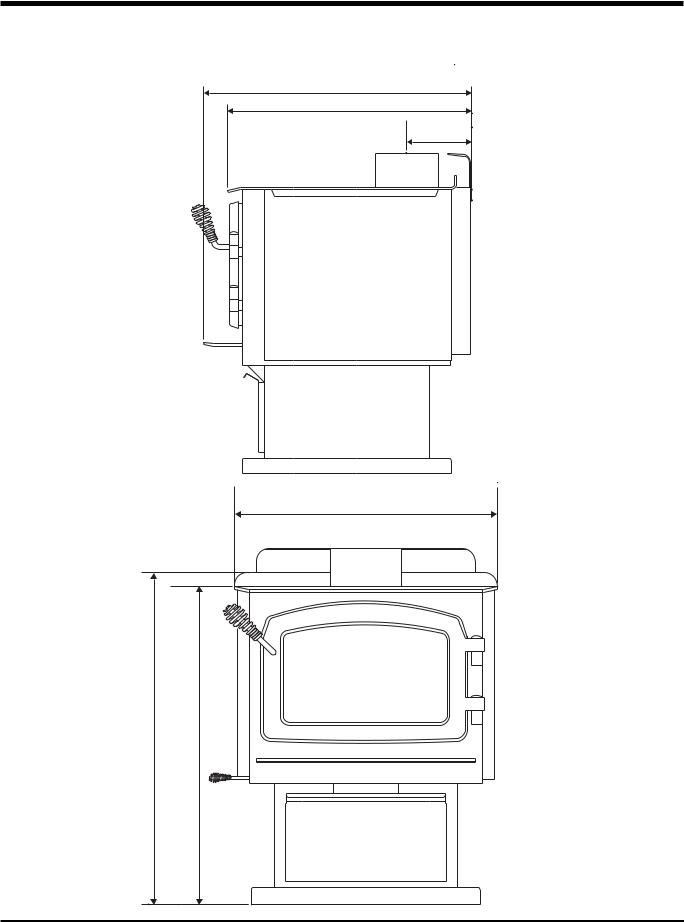
UNIT DIMENSIONS
27-3/8” (695mm)
24-7/8” (632mm)
6-5/8” (168mm)
24” (610mm)
30-3/8"(772mm) |
29-1/8"(740mm) |
6 |
Regency Freestanding Woodstove |
INSTALLATION
RESIDENTIAL
INSTALLATION
1)Please read this entire manual before you install and use your new woodstove. Failure to follow instructions may result in property damage, bodily injury or even death. Be aware that local Codes and Regulations may override some items in this manual.
Check with your local inspector.
2)Select a position for your Regency Stove.
Consult the minimum clearance chart for your model and set the stove in place. For closeclearanceinstallationuselisteddouble wall connector systems.
3)To insure vertical alignment, suspend a plumb bob from the ceiling over the exact center of your stove fl ue and mark a spot on the ceiling to indicate the center of the chimney.
4)Check that the area above the ceiling is clear for cutting. Re-confi rm the clearance from the stove to combustibles to insure that they are within the prescribed limits.
5)This woodstove must be connected to a
UL 103 HT (ULC S629) listed chimney or a code approved masonry chimney with a fl ue liner.
6)Installchimneyaccordingtochimneymanufacturers instructions. The performance of your woodstove is governed to a very large part by the chimney system. Too short a chimney can cause diffi cult start-up, dirty glass,backsmokingwhendoorisopen,and
evenreducedheatoutput.Tootallachimney may prompt excessive draft which can result in very short burn times and excessive heat output. The use of an inexpensive fl ue pipe dampermaybehelpfulinreducingexcessive draft.
CAUTION:Thechimneyshouldbethesame size as the 6" fl ue outlet on the stove. The chimney must be listed as suitable for use with solid fuels. For other types of chimneys check with your local building code offi cials.
Do not confuse a chimney with a type “B” Venting System used for gas appliances as suitable for a wood burning appliance.
For Mobile Home installations refer to that section within this manual.
7)Markthelocationofthepedestalbaseorlegs on the fl oor, then move the stove aside and mark the position of the fl oor protector.
8)The fl oor protector must be of non-combus- tible material and must extend 16" (406mm) in front of the door opening and 6" (152mm) to the sides and rear of the unit. Some areas may require a larger size fl oor protector. See your local inspector. For outside air installation refer to Mobile Home installation instructions within this manual.
NOTE: In Canada, floor protection must extend 18" (450mm) to the front and 8" (200mm) to each side and back of the stove.
9)When the fl oor protection is complete, position the stove with the fl ue collar centered under the installed chimney.
10)In seismically active areas, Regency recommends that your unit is secured to the
fl oor by using the bolt down holes inside the pedestal (the same ones used in Mobile Home installations).
11)For residential installations using 6" "C"
Vent (single wall) the chimney connector must be at least 24 gauge steel. Do not use galvanized pipe. For Mobile Home installation refer to the Mobile Home installation instructions within this manual.
12)Do not connect this unit to a chimney serving another appliance.
13)A chimney connector cannot pass through an attic or roof space, closet or similar concealed space, or a fl oor, ceiling, wall or partition of combustible construction.
In Canada, if passage through a wall, or partition of combustible construction is desired, the installation shall conform to CAN/CSA-B365,InstallationCodeforSolid- Fuel-Burning Appliances and Equipment.
14)Your Regency Woodstove is not to be connected to any air distribution duct.
Emissionsfromburning woodorgascould contain chemicals known to the State of California to cause cancer, birth defects or other reproductive harm.
MODULAR INSTALLATION OPTIONS
The following items are required when assembling your Regency Stove. F2400M unit - the Rear Heat Defl ector is supplied with the stove, but if you choose not to use it you must use the Airmate instead.
Modular Part |
Things to consider when choosing options: |
|
|
Clearances are different. See the Minimum Clearance to Combustible Materials chart in the Installation section of this |
|
F2400M |
manual. Generally you can get closer clearances with the airmate than with the rear heat defl ector. |
|
Airmate OR |
Convection heat with Airmate vs. Radiant Heat with Rear Heat Defl ector. The airmate pushes heat forward and into the |
|
Rear Heat Deflector |
||
room, the rear heat defl ector defl ects the heat upward. Refer to the Installation section within this manual. |
||
|
|
|
F2400M, S2400M |
There are no performance differences with either the pedestal or legs. It is primarily a personal preference. Legs can |
|
Pedestal OR |
be either painted steel, painted cast, or gold plated cast. |
|
|
||
Legs |
Leg installation requires the bottom shield (refer to Leg and Bottom Shield Assembly, Installation section). |
|
|
||
|
|
|
OPTIONS: These can be installed at time of installation or added later: |
||
Modular Option |
Things to consider when choosing options |
|
Blower/Fan |
Adding the blower will increase the area heated by the stove, it can move warm air beyond the room where the stove |
|
is installed (refer to Blower/Fan, Installation section). |
||
|
|
|
Ash Drawer Kit |
Adding the Ash Drawer Kit makes cleaning ashes out of the stove easier and cleaner (refer to Bottom Shield Ash |
|
|
Drawer Kit, Installation section). |
|
Screen Door |
A simple add-on option that will allow you to enjoy the sound, warmth and view of an open fi re. |
|
|
|
|
|
|
|
Regency Freestanding Woodstove |
7 |
INSTALLATION
ROOM AIR
IMPORTANT
For installation using room air for combustion, remove knockout from the pedestal, and/or from the bottom if using a heat shield.
Mobile home installations require the use of outside air.
On pedestal units there are two locations where |
Note: Once the knockout is removed there |
outside air may be adapted to the unit. If us- |
are two tabs remaining. Bend both |
ing the bottom of the pedestal, do not remove |
tabs out for ease of installation when |
knockout from the rear of the pedestal. Only |
attaching outside air. |
remove rear knockout if outside air will be |
|
brought in from the rear. |
|
On leg units outside air can only be brought in |
|
from the bottom of the heat shield. |
|
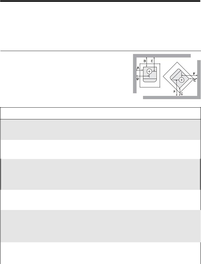
MINIMUM CLEARANCE TO
COMBUSTIBLE MATERIALS
Please read the section below carefully as clearances depend on whether the airmate or the rear heat defl ector is installed on the stove.
Measurements "From Unit" are from the top plate of the stove to a side wall or to a corner, and from the rear heat shield to a back wall.
Clearances may only be reduced by means approved by the regulatory authority.
NOTE: Be aware that local Codes and Regulations may override some clearances listed in this manual. Check with your local inspector.
Residential Installation “C” Vent (Single Wall)
|
Unit |
From Unit |
From Corner |
From Flue Center-Line |
|||
|
|
A |
B |
C |
D |
E |
F |
|
|
|
|
|
|
|
|
|
Medium F2400M with Airmate |
16" (406 mm) |
11" (279 mm) |
6" (152 mm) |
28" (710 mm) |
17.5" (444 mm) |
17.5" (444 mm) |
|
with Rear Deflector |
18" (457 mm) |
12" (304 mm) |
6.5" (165 mm) |
30" (762 mm) |
18.5" (469 mm) |
19.5" (495 mm) |
|
Medium S2400M Step Stove |
16" (406 mm) |
11" (279 mm) |
6" (152 mm) |
28" (710 mm) |
17.5" (444 mm) |
17.5" (444 mm) |
|
|
|
|
|
|
|
|
Residential Close Clearance (To be installed with required pipe components)
When the stove is installed as a close clearance residential unit, a listed double wall connector is required from the stove collar to the ceiling level.
|
Unit |
From Unit |
From Corner |
From Flue Center-Line |
|||
|
|
A |
B |
C |
D |
E |
F |
|
Medium F2400M with Airmate |
15" (381 mm) |
5.5" (139 mm) |
4" (101 mm) |
27" (685 mm) |
12" (304 mm) |
15.5" (393 mm) |
|
with Rear Deflector |
15" (381 mm) |
6.5" (165 mm) |
6" (152 mm) |
27" (685 mm) |
13" (330 mm) |
17.5" (444 mm) |
|
Medium S2400M Step Stove |
15" (381 mm) |
5.5" (139 mm) |
4" (101 mm) |
27" (685 mm) |
12" (304 mm) |
15.5" (393 mm) |
|
|
|
|
|
|
|
|
Mobile Home Close Clearance (To be installed with required pipe components)
"C" Vent single wall pipe is not approved for Mobile Home installations. (Refer to Mobile Home Instructions.)
Unit |
From Unit |
|
From Corner |
From Flue Center-Line |
|||
|
A |
B |
C |
D |
E |
F |
|
|
|
|
|
|
|
|
|
Medium F2400M |
|
|
|
|
|
|
|
with Airmate |
15" (381 mm) |
|
5.5" (139 mm) |
4" (101 mm) |
27" (685 mm) |
12" (304 mm) |
15.5" (393 mm) |
with Rear Deflector |
15" (381 mm) |
|
6.5" (165 mm) |
6" (152 mm) |
27" (685 mm) |
13" (330 mm) |
17.5" (444 mm) |
Medium S2400M Step Stove |
15" (381 mm) |
|
5.5" (139 mm) |
4" (101 mm) |
27" (685 mm) |
12" (304 mm) |
15.5" (393 mm) |
|
|
|
|
|
|
|
|
|
|
|
|
|
|
|
|
8 |
Regency Freestanding Woodstove |
INSTALLATION
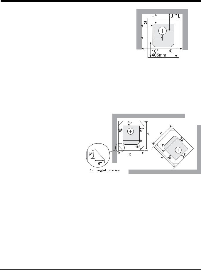
Minimum Alcove Clearance to Combustible Materials
The Regency Freestanding models have been alcove approved and must be installed with a listed double wall connector to the ceiling level.
Note: Minimum alcove ceiling height - 84"
Maximum depth of alcove - 36"
|
|
|
|
|
|
|
|
|
|
|
|
|
|
|
|
|
|
|
|
|
|
|
|
|
|
|
|
|
|
|
|
|
|
|
|
|
|
|
|
|
|
|
|
|
|
|
|
|
From |
From Flue |
Min. |
Min.Hearth |
|
||||||
|
|
Unit |
|
Unit |
Center-line |
Width |
to Rear Wall |
|
||||||
|
|
|
G |
H |
I |
J |
K |
L |
|
|||||
|
Medium F2400M |
with Airmate |
15" (381 mm) |
5.5" (139 mm) |
27" (685 mm) |
12" (304 mm) |
54" (1371 mm) |
48" (1219 mm) |
|
|||||
|
|
with Rear Deflector |
15" (381 mm) |
6.5" (165 mm) |
27" (685 mm) |
13" (330 mm) |
54" (1371 mm) |
49" (1244 mm) |
|
|||||
|
|
|
|
|
|
|
|
|
|
|
|
|
|
|
|
Medium S2400M Step Stove |
15" (381 mm) |
5.5" (139 mm) |
27" (685 mm) |
12" (304 mm) |
54" (1371 mm) |
48" (1219 mm) |
|
||||||
|
|
|
|
|
|
|
|
|
|
|
|
|
|
|
Floor Protection
A combustible fl oor must be protected by non-combustible material (like tile, concrete board, or certifi ed to UL-1618 or as defi ned by local codes) extending beneath the heater and a minimum of 6" (152mm) from each side and minimum 16" (406mm) from the front face of the stove and minimum 6"
(or the rear clearance to combustibles whichever is smaller) from the rear of the stove.
When installed with horizontal venting, non-combustible floor protection must beneath the fl ue pipe and extend 2" (51mm) beyond each side.
Minimum Overall Width (X) of Floor
Protector for all installations:
Stove |
F2400M |
36" (914 mm) |
|
|
|
|
|
|
|
|
|
|
||
Step Stove |
S2400M |
36" (914 mm) |
|
NOTE:InCanada,floor protection mustextend18" (450mm) tothe |
|
|||||||||
|
|
|
|
|
|
|
front and 8" (200mm) to each side and back of the stove. |
|
||||||
|
|
|
|
|
|
|
|
|
|
|
|
|
|
|
Minimum Overall Depth (Y) of Floor Protector |
|
|
|
|
|
|
|
|
|
|
||||
|
|
|
|
|
|
|
|
|
|
|
|
|
||
|
|
Residential |
|
Residential |
Mobile Home |
|
Alcove |
|
|
|||||
Unit |
|
|
"C" Vent |
|
Close Clearance |
Close Clearance |
|
|
|
|
||||
|
|
|
|
|
|
|
|
|
|
|
|
|
|
|
|
|
Y |
|
Z |
|
Y |
|
Z |
Y |
|
Z |
Y |
Z |
|
Medium F2400M |
|
|
|
|
|
|
|
|
|
|
|
|
|
|
with Airmate |
|
46" (1168 mm) |
6" (152 mm) |
45"* (1143 mm) |
5" (127 mm) |
45" (1143 mm) |
5" (127 mm) |
45"* (1143) |
5" (127 mm) |
|||||
with Rear Deflector |
46" (1168 mm) |
6" (152 mm) |
45" (1143 mm) |
5" (127 mm) |
45" (1143 mm) |
5" (127 mm) |
45" (1143) |
5" (127 mm) |
||||||
|
|
|
|
|
|
|
|
|
|
|
|
|||
Medium S2400M |
|
46" (1168 mm) |
6" (152 mm) |
45"* (1143 mm) |
5" (127 mm) |
45" (1143 mm) |
5" (127 mm) |
45"* (1143) |
5" (127 mm) |
|||||
- Step Stove |
|
|
|
|
|
|
|
|
|
|
|
|
|
|
|
|
|
|
|
|
|
|
|
|
|
|
|
|
|
*The rear clearance to combustibles is less than 6" (, for corner installations the rear corners may be angled to take advantage of the closer clearances.
Regency Freestanding Woodstove |
9 |
 Loading...