


26002
Installation Instructions
REESE Dual Cam HP
High-Performance Sway Control
Part Numbers:
26002
INDEX
1. INSTALLATION & ASSEMBLY P. 2-4
2. PRE-INSTALLATION (TOW VEHICLE MAY NOT BE PRESENT) P. 4
2. INSTALLATION WITH TOW VEHICLE PRESENT P.4-5
3. TUBULAR FRAME DUAL CAM HP FRAME PLATE INSTALLATION P. 5-6
4. C-CHANNEL FRAME DUAL CAM HP FRAME PLATE INSTALLATION P. 6
5. CAM ARM ADJUSTMENT P. 7
6. BEFORE EACH TRIP & MAINTENANCE P. 7
7. NOTES P. 8
8. LIMITED LIFETIME WARRANTY P. 8
© 2010 Cequent Performance Products, Inc.
Sheet 1 of 30 26002IN 09/03/13 Rev. N
j
Qty. (2) Dual Cam HP Cam Arm Assembly
k
Qty. (2) Hanger Bracket
l
Qty. (6) ½ - 13 Thread Forming Screw*
m
Qty. (2) ½-13 X 3 ½” Square Head Bolt*
n
Qty. (6) ½-13 Hex Nut*
o
Qty. (2)
½” Lock Washer**
p
Qty. (4)
½-13 X 1 ½” Grade 5 Bolt**
Do Not Exceed Lower of Towing Vehicle Manufacturer’s Rating, or
Trailer Manufacturer’s Rating
Form: F205 Rev A 5-6-05
DEALER/INSTALLER:
(1) Provide this Manual to end user
END USER:
(1) Read and follow this Manual every time you use Dual Cam HP.
(2) Save this Manual for Future Reference.
(3) Pass on copies of Manual to any other users or owner.
j
k
l*
m*
n*
WARNING:
Failure to follow all of these instructions may result in death or serious injury!
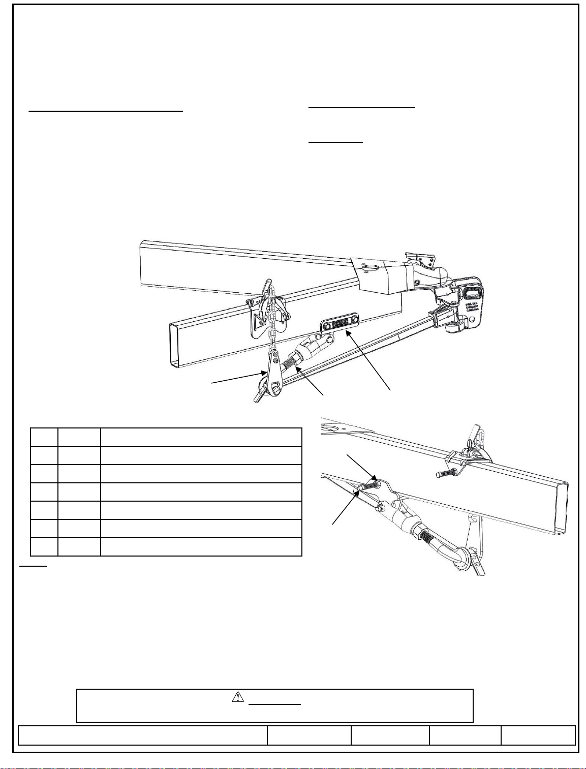
Figure 1
*For Tubular Style Frame Attachment
**Not Shown, For C-Channel Style Frame Attachment
DUAL CAM HP ASSEMBLED
Equipment Required:
Wrenches: 1-1/2” Open End, ¾” Open End
Drill Bits: 7/16”, 17/32” & Center Drill (Pilot Drill)
Fastener Kit: 100126
½” Open End, ¾” Socket & Ratchet
Other: 8 – 10” C-Clamp, Tape Measure, Light Penetrant Oil
For Installation or Operation Support contact CPP Technical Service: 1-888-521-0510.
Figure 2
Inside View of Trailer
Frame
ADJUSTMENT NUT
LOCK WASHER
YOKE
LOCK NUT
© 2010 Cequent Performance Products, Inc.
Sheet 2 of 30 26002IN 09/03/13 Rev. N
Form: F205 Rev A 5-6-05
INSTALLATION
Figure 3
1. Locate both hanger brackets included in the kit (item 2, figure 1). Install U-bolt and chain from your Weight Distribution Kit
on each hanger bracket as shown in figure 3 (if installing Dual Cam HP on an existing weight distribution kit, the U-bolts and
chains will need to be removed from each spring bar before they can be installed on the hanger brackets).
The U-bolts must be installed in the ends of the chains (last link) as shown in figure 3.
Installation Instructions
REESE Dual Cam HP
High-Performance Sway Control
2. Install 2 lock nuts per U-bolt, tighten u-bolt nuts. Make sure at least 2 threads are showing past the ends of the nuts.
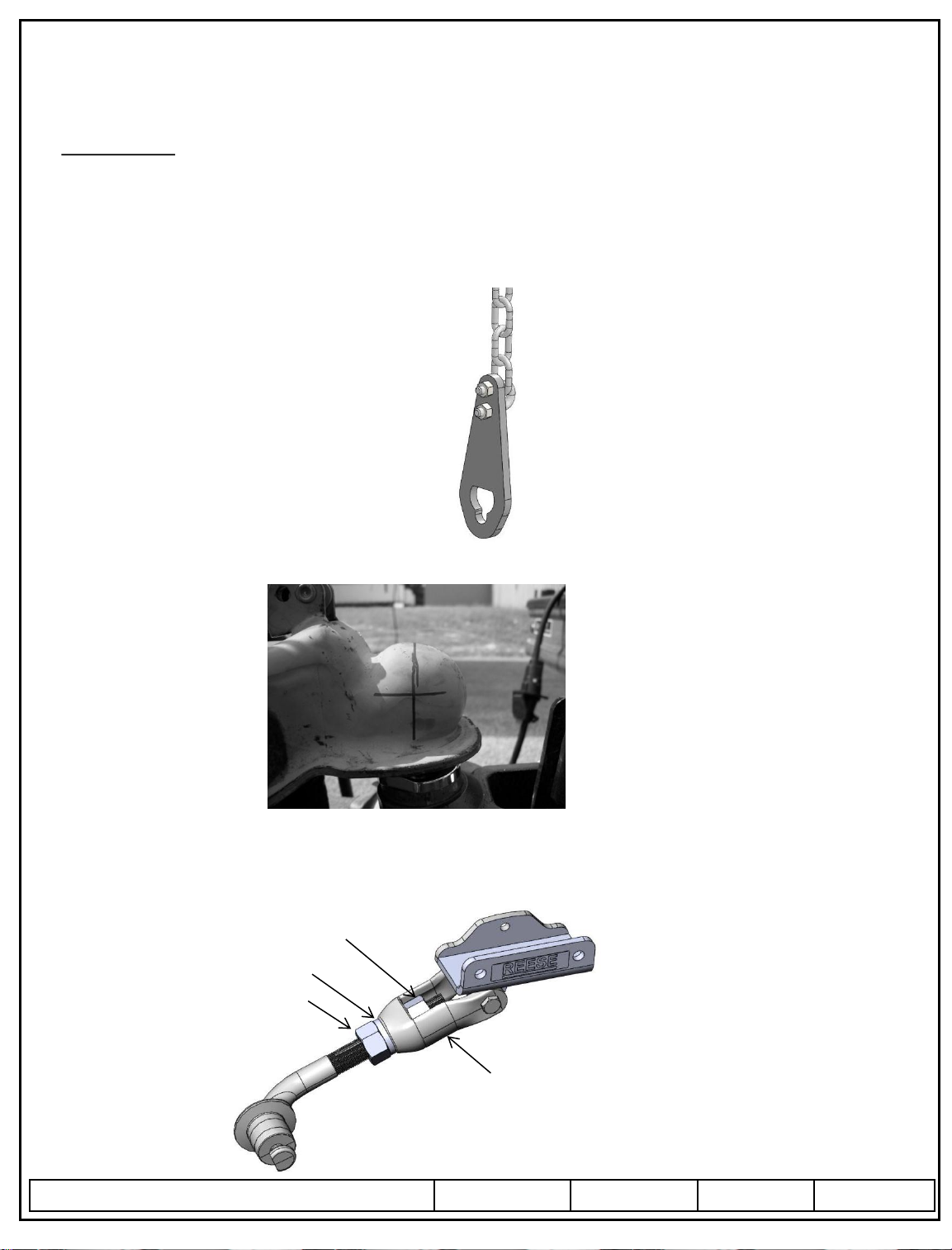
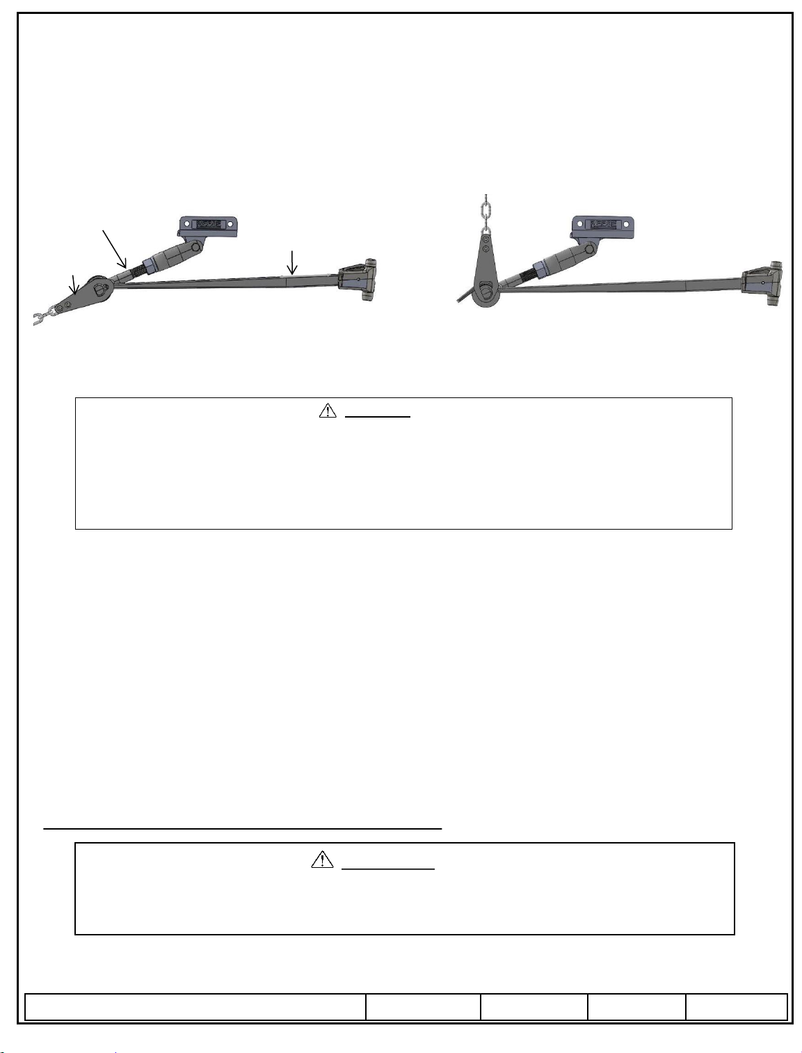
4. Position the adjustment nut and locking nut to the outermost positions as shown in figure 5. If the
adjustment is difficult, as the adjustment nut must be turned by hand, apply a small amount of light penetrating oil such as
WD40 or PB Blast to the threads of the cam arm. Work the adjustment nut back or forward to get the penetrating oil into the
threads until the adjustment nut moves freely to the desired position.
3. Using a grease pencil or suitable marking device such as a marker and a straight edge locate and mark the center of the hitch
ball on the coupler both horizontally and vertically as shown in figure 4 . This reference point will be used to locate the cam
arm assembly position. Mark both sides of the coupler.
Figure 4
Figure 5
© 2010 Cequent Performance Products, Inc.
Sheet 3 of 30 26002IN 09/03/13 Rev. N
Form: F205 Rev A 5-6-05
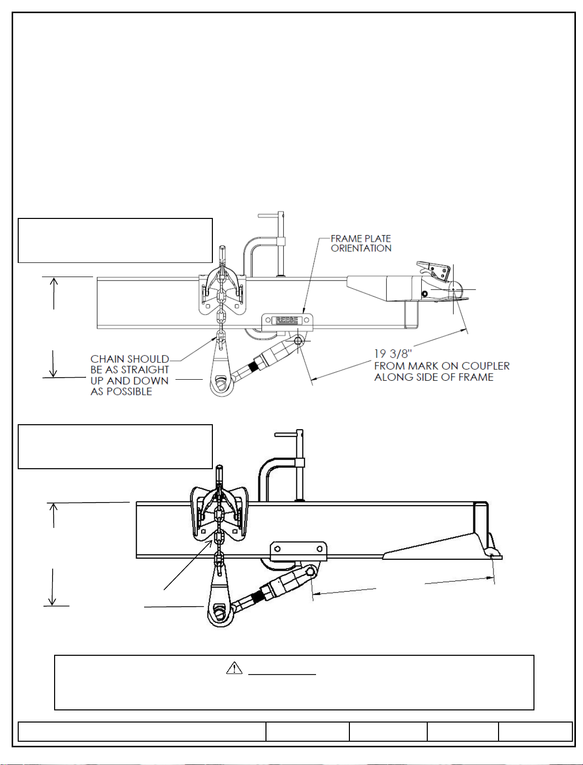
The Measurements in figures 6, 6A, 7 & 7A are guidelines, adjustment of the cam arm length via the adjustment nut (Figure 5)
may be required after hookup in later instructions of this manual Cequent Performance Products, Inc. is not responsible for
damage incurred due to disregarding any part of this manual.
CAUTION:
5. Using a C-clamp suitable to accommodate your trailer frame height and the Dual Cam HP frame plate, temporarily clamp the
Dual Cam HP cam arm assembly to the trailer frame and Dual Cam HP frame plate as shown in figure 6 for Trunnion style
Weight Distribution kits, for Round Bar style Weight Distribution Kits, follow the dimensions in figure 7.
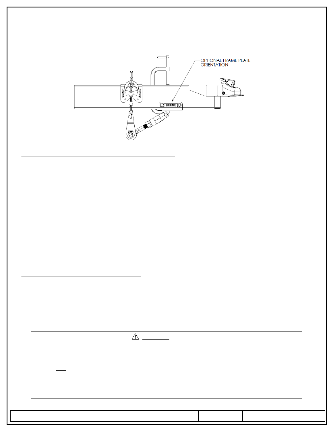
6. Position the Frame Plate at the dimension shown for your type Weight Distribution Kit (Trunnion Style or Round Bar.
Standard coupler or bottom mounted).
Measure from the mark on the ball coupler to the center of the cam arm pivot bolt as shown in figure 6 or figure 7 on the next
page. If the frame plate interferes with any part of the trailer frame, the orientation can be changed by switching sides, see
figure 8 for optional Frame plate orientation – maintain the same coupler center to cam arm pivot dimension regardless of frame
plate orientation.
7. Position the Chain Hanger temporarily above the cam arm. (Upon hook-up, the Hanger position must
be adjusted to be sure the chain is vertical before towing). Tighten the Chain Hanger bolt shown in figure 2 against the frame.
Figure 6 – Cam Arm Approximate Locations for Trunnion Style Weight Distribution kits
Installation Instructions
REESE Dual Cam HP
High-Performance Sway Control
Trunnion Style Set Up Locations
(Standard Coupler)
20-1/2
Trunnion Style Set Up Locations
(Bottom Mount Coupler)
FROM MARK ON COUPLER
ALONG SIDE FRAME
8. If you have a bottom mounted coupler it may be necessary
for you to tilt the ball mount as far forward towards the front
of the tow vehicle as possible.
Figure 6A – Cam Arm Approximate Locations for Trunnion Style Weight Distribution kits
CHAIN SHOULD
BE AS STRAIGHT
UP AND DOWN
AS POSSIBLE
Approximate desired
working range on a 6” tall
frame.
12”-13”
Approximate desired
working range on a 6” tall
frame.
12”-13”
© 2010 Cequent Performance Products, Inc.
Sheet 4 of 30 26002IN 09/03/13 Rev. N
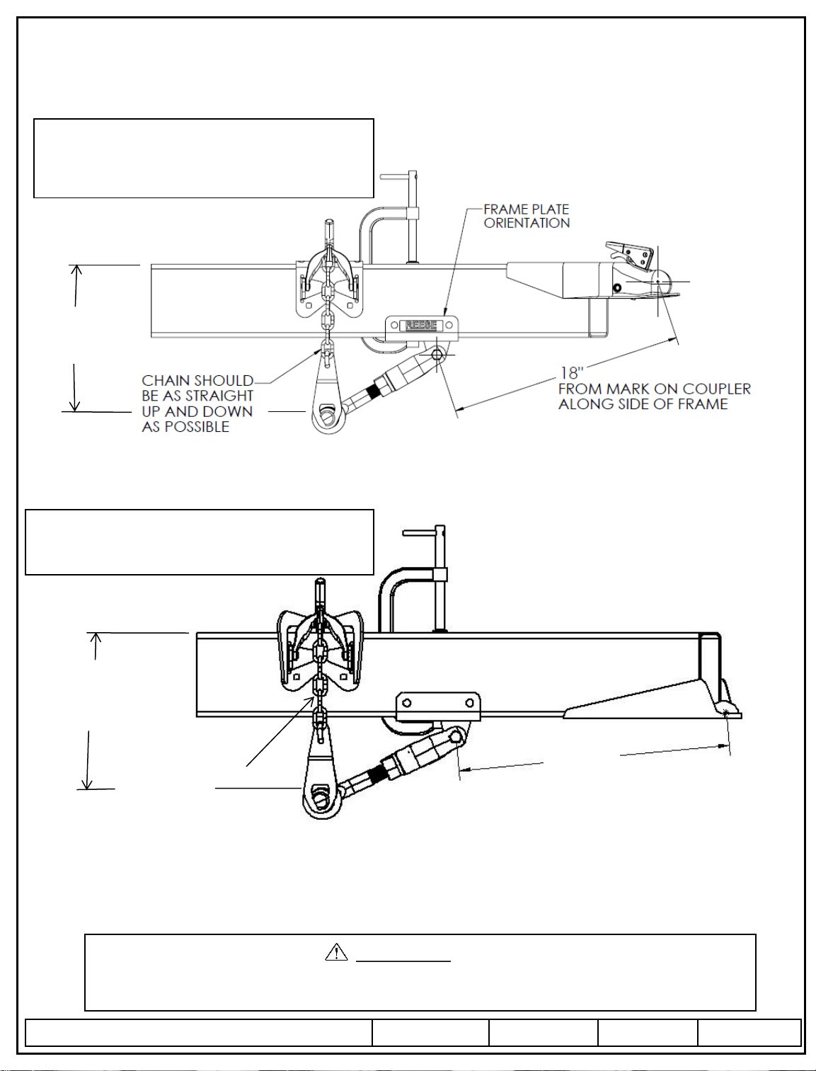
Figure 7 – Cam Arm Approximate Location for Round Bar Weight Distribution kits
Round Bar Set Up Locations
(Standard Coupler)
The Measurements in figures 6, 6A, 7 & 7A are guidelines, adjustment of the cam arm length via the adjustment nut (Figure 5)
may be required after hookup in later instructions of this manual Cequent Performance Products, Inc. is not responsible for
damage incurred due to disregarding any part of this manual.
CAUTION:
If you have a bottom mounted coupler it may be necessary for you to tilt the ball mount as far forward
towards the front of the tow vehicle as possible.
19-1/8”
Round Bar Set up Locations
(Bottom Mounted Coupler)
FROM MARK ON COUPLER
ALONG SIDE OF FRAME
Figure 7A – Cam Arm Approximate Location for Round Bar Weight Distribution kits
REESE Dual Cam HP
High-Performance Sway Control
Installation Instructions
CHAIN SHOULD
BE AS STRAIGHT
UP AND DOWN
AS POSSIBLE
Approximate desired
working range on a 6” tall
frame.
12”-13”
Approximate desired
working range on a 6” tall
frame.
12”-13”
© 2010 Cequent Performance Products, Inc.
Sheet 5 of 30 26002IN 09/03/13 Rev. N
Form: F205 Rev A 5-6-05
Installation Instructions
REESE Dual Cam HP
High-Performance Sway Control
Figure 8
PRE-INSTALLATION (TOW VEHICLE MAY NOT BE PRESENT)
1. If the tow vehicle is not available at the time of installation of the Dual Cam HP system, position the yolk centered on the
threads of the cam arm (Approximately 2” from either end of the threaded portion of the cam arm. Run the adjustment nut
down to meet the yolk. Tighten the locking nut until the lock washer is fully compressed and continue to the Frame Plate
Installation portion of this manual for your specific frame style; Tubular Frame or C-Channel Frame.
2. Pass this manual along to the customer/end user of this product and inform them that minor adjustments to their cam arm
length may be required depending on head tilt of the WD system, number of chains used for proper weight distribution, tow
vehicle variance and/or; changes in tongue weight of their trailer as all of these variables will slightly affect the proper position
of the cam with respect to proper seating in the detent of the cam arm.
3. Direct the customer to the INSTALLATION WITH TOW VEHICLE PRESENT portion of this manual for hook-up procedure,
and fully explain proper seating of the cam within the spring bar detent. Refer them to their specific Weight Distributing Hitch
Instruction manual and be sure they follow the INITIAL HOOKUP section of their Weight Distribution Kit Manual for first
time hook-up and/or any changes in the variables listed in item 2. of this section occur.
4. BE SURE to pass along the Towing Information Packet (P/N: 110400) to the customer/end user and BE SURE they
understand the material within the Towing Information Packet for safe towing.
INSTALLATION WITH TOW VEHICLE PRESENT
NOTE: Set-up and adjust weight distribution hitch per the installation instructions for your Weight Distribution Hitch.
1. Connect the trailer to the tow vehicle. Tow vehicle and trailer should be on level ground and in a straight line. Raise the
tongue and rear of the vehicle enough to install the spring bars onto the dual cam arm with the trailer tongue jack
(approximately 6”-12” or until the spring bar can be lifted with the supplied lifting handle with very little effort, this will vary
depending on spring bar rating and head tilt adjustment).
WARNING:
Avoid putting any part of your body under the trailer or between the truck and trailer. Unexpected or
accidental movement of the truck or the trailer can cause serious injury or death
If you must place any part of your body under the trailer or between the truck and trailer you MUST
perform ALL of the following steps:
Check that the truck transmission is in park
Check that the emergency brake is set
Block in front of and behind all trailer tires
Check that the trailer jack foot is resting on firm ground
FOLLOW THE SAME MEASUREMENTS FOR THIS
ORIENTATION AS SHOWN IN FIGURE 6 OR 7.
CAM
HANGER
BRACKET
SPRING BAR
1. With the C-clamps still in place, center punch (2) holes in the frame for each bracket..
© 2010 Cequent Performance Products, Inc.
Sheet 6 of 30 26002IN 09/03/13 Rev. N
Form: F205 Rev A 5-6-05
Installation Instructions
REESE Dual Cam HP
High-Performance Sway Control
2. Install the spring bars into the ball mount head. Position the spring bar over the cam portion of the cam arm.
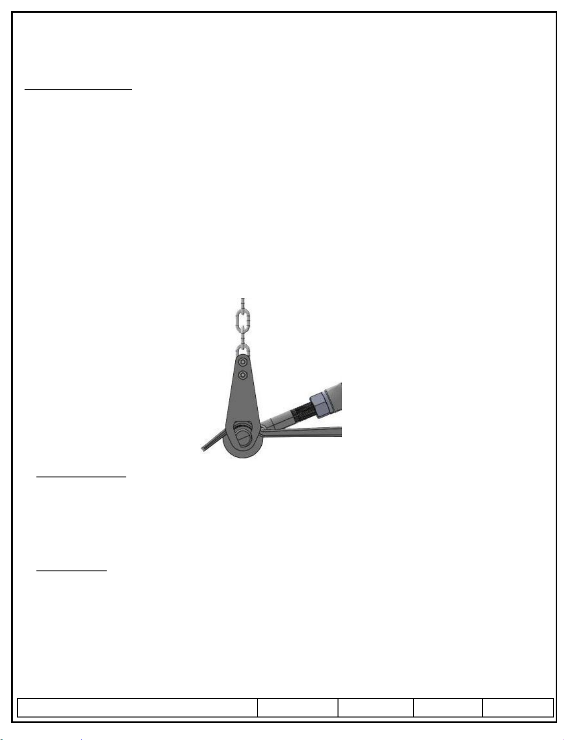
3. Install the Hanger Bracket (with the ends of the u-bolts facing inward) and Chain onto the cam by slipping the keyed slot of the
hanger bracket over the button end of the cam arm (figure 9). Rotate Hanger bracket to the vertical position and pull chain
vertical to the chain attachment point on the snap-up bracket (Figure 10).
Figure 9
Figure 10
4. Raise the chains until they meet the hook of the snap-up bracket, using the chain link furthest down the chain that allows you to
close the snap-up bracket by hand (without the supplied lifting tube – this is generally the 2
nd
or 3
rd
link from the free end of the
chain for most installation). Use the same link # for both sides of the trailer. Lift both spring bars with the snap-up brackets
and install the keeper pin in the snap-up bracket. Be sure that the hanger bracket is fully engaged in the slot of the cam arm.
5. Lower the trailer tongue jack.
6. Check that the cam is properly seated properly in the detent of the spring bar (figure 14). If the cam arm assembly dose not
automatically seat in the detent of the spring bar, rap the end of the cam arm with a
mallet or hammer until it seats into the spring bar detent as shown in figure 14.
7. Once the cam arms are properly positioned in the detent of the spring bar. Check the ride height of the tow vehicle per your
Weight Distributing Hitch Kit; specifically the Initial Hookup section of that manual. It may be necessary to adjust the number
of links engaged or the ball mount tilt for proper weight distribution for your tow vehicle and trailer. Re-seating of the
Cam Arm Assemblies in the spring bar detent may be necessary until the Initial Hookup requirements are met.
Run the adjustment nut shown in figure 5 down to meet the yolk. Tighten the locking nut shown in figure 5 until the locking
washer is fully compressed. This process needs to be done for both cam assemblies, i.e. both sides of the trailer frame.
8. The Cam Arm Assemblies are now ready to be permanently mounted to the trailer frame. Follow the proper instruction for
frame plate installation of this manual for your particular frame type.
TUBULAR FRAME DUAL CAM HP FRAME PLATE INSTALLATION
Before drilling, make sure there are no obstructions in the trailer frame where the intended bolt holes are to be drilled, such as
trailer wiring and or electric brake beak-away switch.
DO NOT drill through the opposite wall of the frame tube.
CAUTION:
WARNING:
When lifting/lowering Snap-Up Bracket, Avoid putting any part of your body in the path of the lifting handle
and under the cam arm and spring bars. Components of this system are loaded with substantial force and
could shift position or drop suddenly causing serious injury or death.
Never Raise or Lower Snap-Up Brackets without raising the trailer tongue jack to remove the load from the
spring bars and cam arms. Failure to do so could cause serious injury.
VERTICAL
2. Drill (2) 7/16” holes in each side of the frame where the punched center marks were made. The use of a center drill or small
pilot hole may be very helpful prior to final drilling.
3. Install (2) supplied ½-13 Thread Forming Screws (Item 3, figure 1).
Repeat for opposite side and torque (4) ½-13 Thread Forming Screws to 50 ft-lb.
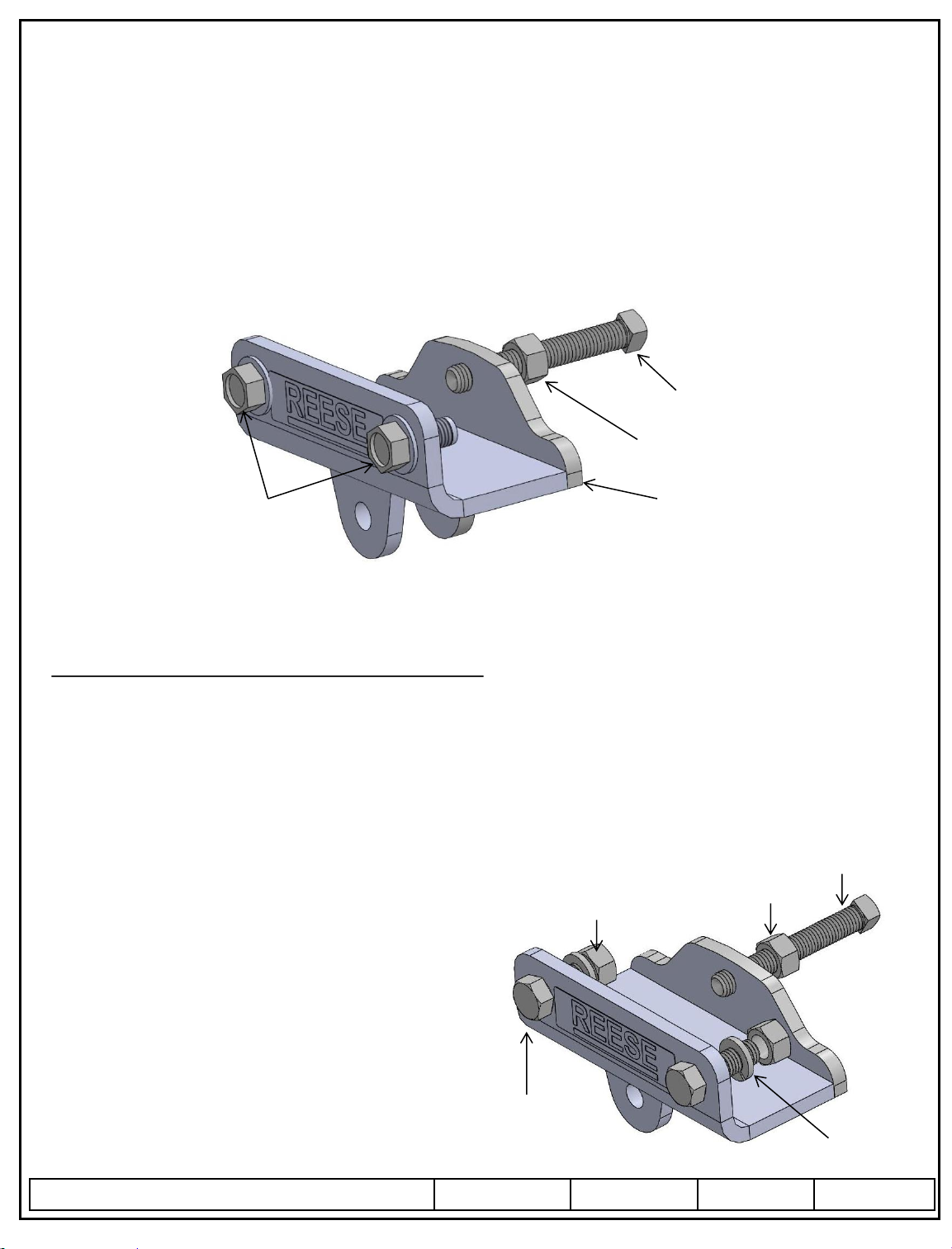
4. Install ½-13 Hex Nut (Jam Nut)onto the ½-13 X 3 ½” Square Head Bolts and Install into the frame brackets as shown in figure 11.
5. Tighten the Set Screw until it contacts the trailer frame. Then proceed to tighten ¼ to ½ turn (DO NOT OVERTIGHTEN SET
SCREW). Tighten the Jam Nut preventing the set screw from backing out while in use. Repeat for other side of trailer frame.
6. Remove C-Clamps from frame.
© 2010 Cequent Performance Products, Inc.
Sheet 7 of 30 26002IN 09/03/13 Rev. N
Form: F205 Rev A 5-6-05
Installation Instructions
REESE Dual Cam HP
High-Performance Sway Control
C-CHANNEL DUAL CAM HP FRAME PLATE INSTALLATION
NOTE: Some C-Channel frames may have square outside corners that do not allow the frame plate to contact the
bottom of the frame. For these type of frames a ½” flat washer (Not Supplied) is required between the outside of the
trailer frame and the frame plate. The bottom of the frame plate MUST contact the bottom of the trailer frame.
1. With the C-clamps still in place, center punch (2) holes in the frame for each bracket.
2. Drill (2) 17/32” holes in each side of the frame where the punched center marks were made. The use of a center drill or small
pilot hole may be very helpful prior to final drilling.
3. Install the (2) supplied ½-13 x 1 ½” Bolts, ½” Lock Washers & ½” Nuts (items 5,6 & 7) figure 12.
Repeat for opposite side and torque (4) ½-13 Bolts to 85 ft-lb.
4. Install ½-13 Hex Nuts onto the ½-13 X 3 ½” Square Head Bolts and
install into the frame brackets as shown in figure 13.
5. Tighten the Set Screw until it contacts the trailer frame.
Then proceed to tighten ¼ to ½ turn (DO NOT OVERTIGHTEN
SET SCREW). Tighten the Jam Nut preventing the set screw
from backing out while in use. Repeat for other side of trailer frame.
6. Remove C-Clamps from frame.
Figure 13
SET SCREW
JAM NUT
NUT
LOCK
WASHER
HEX HEAD
BOLT
Figure 11
SET SCREW
JAM NUT
FRAME
BRACKET
FLANGE HEAD,
THREAD
FORMING
SCREWS
© 2010 Cequent Performance Products, Inc.
Sheet 8 of 30 26002IN 09/03/13 Rev. N
Form: F205 Rev A 5-6-05
BEFORE EACH TRIP:
1. CHECK YOUR EQUIPMENT: Check that condition of all of your towing equipment and keep it in top condition.
2. Check that the torque of all fasteners are in accordance to this manual.
3. Re-Check spring bar detent and cam alignment, and periodically while towing for the best performance.
4. Check for any excessive wear to any of the components of this system.
MAINTENANCE:
1. DO NOT – use grease on the cams or cam arms.
2. If noise of the system is offensive, a very light coating of lubricant such as Vaseline may be used on the portion of the
cam where the spring bar rides on the cam.
Tongue weights in excess of 1,200 lbs. may require the use of such a lubricant to prevent excessive wear.
3. Keep all painted parts painted to prevent rust and maintain a good appearance. (Do Not paint over labels)
Installation Instructions
REESE Dual Cam HP
High-Performance Sway Control
CAM ARM ADJUSTMENT
1. Be sure that the truck and trailer are adjusted properly per the instructions for your Weight Distribution Hitch, pull forward far
enough to be sure the truck and trailer are in a straight line. (Picking a point at a distance away from the vehicle (about 100
yards) drive forward toward that point keeping the steering perfectly straight until the truck and trailer are perfectly in a straight
line.)
2. Go to each cam arm and check to see that the cam is perfectly centered in the detent of the spring bar. Make adjustments to
the cam arm length as required, it is important to have the cam arm/spring bar detent exactly as shown in figure 14.
3. Before adjustments to the cam arm length can be made, raise the trailer tongue jack and lower the snap-up brackets. Loosen the
Locking nut (figure 5) and move the adjustment nut (figure 5) until the cam is centered into the detent of the spring bar (figure
14). After making adjustments, lift both snap-up brackets and install retainer clips; lower the trailer tongue jack. Repeat step 2
of this section
3. Adjust the position of the snap-up brackets as needed, the chain should be perfectly vertical while in use to avoid damage to the
snap up bracket itself.
* From time to time, with changing towing/loading conditions, it may be necessary to use a different chain link to properly level
the tow vehicle (See your Weight Distribution Kit Installation Instructions). Anytime a different link is used, the cam arm
must be readjusted.
Figure 14
Installation Instructions
Snap Up Bracket
TOOLS NEEDED:
Drill Bits: 7/16”, 9/16” & ¼”
© 2010 Cequent Performance Products, Inc.
Sheet 9 of 30 26002IN 09/03/13 Rev. N
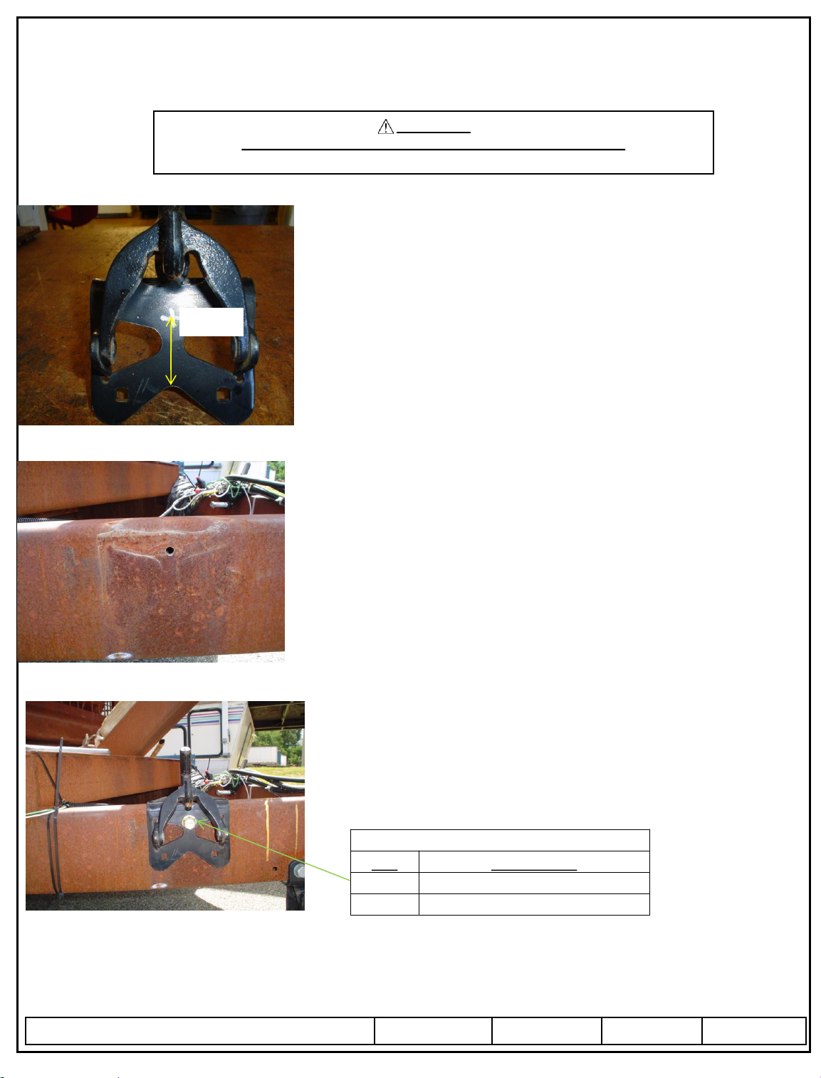
WARNING:
Read all instructions before installing the additional bolt.
Failure to follow all of these instructions may result in death or serious injury!
For Installation or Operation Support contact CPP Technical Service: 1-888-521-0510.
2-1/4”
•Installation of an additional bolt into the snap up bracket when using
a Jayco RV with a coupler mounted to the bottom of the frame.
•If a hole does not already exist, mark the location of the hole to be
drilled into the snap up bracket. Center the hole from left to right and
place it 2-1/4” above the arc in the bracket. See the picture at left.
•Before the bracket is placed on the frame, drill a 9/16” hole in the
bracket
•Place the bracket in the correct place on the frame as directed in the
product instructions or replace it where it was if it had already been
installed.
•Using the hole in the bracket as a guide, drill a ¼” pilot hole. Be sure
to stay centered in the bracket hole.
• One method to stay centered is to use the 9/16” drill first. Just put a
small dimple into the frame with the 9/16” bit. Then finish drilling
with the ¼” drill bit and then a 7/16” drill bit to get the final hole. See
pilot hole to the left.
•Install the ½” self tapping screw into the hole in the bracket and
frame. Tighten it to 50 ft/lbs.
•Re-tighten the ½” set screw on the inside of the frame. Turn only
¼ to ½ of a turn after making contact with the frame.
Cequent Performance Products, Inc.
47912 Halyard Dr. Suite 100
Plymouth, MI 48170
PARTS LIST
QTY DESCRIPTION
2
1/2" x 1.00" SELF TAPPING SCREW
1
INSTRUCTION SHEET
 Loading...