


INSTALLATION AND OPERATING
INSTRUCTIONS
Y-200 Series
Electronic Boiler Sequencer & Outdoor
Reset Control System
|
|
|
|
|
|
|
|
|
|
|
|
Catalog No. 5000.62I |
Effective: 11-03-10 |
Replaces: 09-28-09 |
P/N 241125 Rev. 10 |
||

is a registered trademark of Underwriters Laboratories Inc. ®
Rev. 10 reflects the following:
Changes to: Fig. 7 on page 11, Program Mode instructions on page 16, Illustrated Parts List on page 38
Additions: None
Deletions: None
2

CONTENTS
ImPORTANT SAfETY |
|
|
INSTRUCTIONS |
4 |
|
INTRODUCTION |
4 |
|
Concept of Operation |
4 |
|
Y-200 Controller Configurations |
5 |
|
Y-200 Options |
5 |
|
INSTALLATION |
6 |
|
Mechanical Installation |
6 |
|
Electrical Installation |
6 |
|
Controller Field Wiring |
8 |
|
Communication Field Wiring |
9 |
|
Air Temperature Sensor Installation |
9 |
|
Water Temperature Sensor Installation |
10 |
|
Power Test |
11 |
|
Installation Verification Procedure |
12 |
|
CONTROLLER |
|
|
fAmILIARIzATION |
12 |
|
Control Screens |
13 |
|
Circuit Board Layout |
15 |
|
Keypad |
16 |
|
Control Screen Displays & |
|
|
Programming |
17 |
|
01 |
Initial Screen |
17 |
02 |
Primary Parameters |
17 |
03 |
Control Band |
18 |
04 |
Offset |
19 |
05 |
Holiday |
20 |
06 |
Reset Ratio |
20 |
07 |
System Status |
22 |
08 |
Water Temperature |
23 |
09 |
Outdoor Cut-Off Temperature |
23 |
10 |
Outdoor Cut-Off Deadband |
23 |
11 System Monitor |
24 |
|
12 |
System Temperatures |
24 |
13 Auxiliary Delay |
25 |
|
14 |
Boiler/Stage On Delay |
25 |
15 |
Boiler/Stage Off Delay |
26 |
16 |
PID |
26 |
17 |
System Temperatures |
27 |
18 |
Lead Change Time |
27 |
19 |
Password |
28 |
20 |
Setup |
28 |
21 |
System Test |
29 |
22 |
Set Password |
29 |
23 |
Water Temperature Limits |
29 |
24 |
Master Unit |
30 |
25 |
Slave Unit |
31 |
26 |
LonWorks |
31 |
27 |
Factory Defaults |
31 |
28 |
User Defaults |
32 |
29 |
Modem Password |
32 |
30 Alarm Call Telephone |
33 |
|
31 Alarm Call ID |
33 |
|
32 Alarm Call Retry |
33 |
|
33 Alarm Call Events |
33 |
|
34 |
PID |
34 |
Master Unit with Slaves |
34 |
|
Y-200 Master/Slave Diagram |
36 |
|
Sensor Resistance |
37 |
|
Illustrated Parts List |
38 |
|
WARRANTY |
39 |
|
3
Y–200 SERIES ELECTRONIC BOILER CONTROL
SAfETY INSTRUCTIONS
NOTE: These instructions are intended for use by qualified personnel who are specifically trained and experienced in the installation of this type of equipment and related system components. Installation and service personnel may be required by some states to be licensed. If your state requires certification, be sure your contractor bears the appropriate license. Only qualified persons shall attempt to repair this equipment. Repair must be according to these instructions.
WARNING: Improper installation, adjustment, alteration, service or maintenance may damage the equipment, create a hazard resulting in asphyxiation, explosion, fire, electric shock, personal injury or property damage, and will void the warranty.
CAUTION: MORE THAN ONE (1) SUPPLY SOURCE. THIS APPLIANCE HAS PROVISIONS TO BE CONNECTED TO MORE THAN ONE (1) SUPPLY SOURCE. TO REDUCE THE RISK OF ELECTRIC SHOCK, DISCONNECT ALL SUCH CONNECTIONS BEFORE SERVICING.
CAUTION: RISK OF ELECTRIC SHOCK. MORE THAN ONE (1) DISCONNECT SWITCH MAY BE REQUIRED TO DE-ENERGIZE THE EQUIPMENT BEFORE SERVICING.
Thank you for selecting the Raypak Y–200 Series Electronic Boiler Control. It is our sincere hope that you will enjoy its outstanding design, ease of use and energy-saving features.
Please Register
Before proceeding any further, please take a moment to complete the enclosed user registration form and mail a copy to: Raypak, Inc., Department Y–200, 2151 Eastman Avenue, Oxnard, CA 93030.
INTRODUCTION
The Y-200 Series Electronic Boiler Control (controller) is a microprocessor-based boiler management system designed to control either single or multiple stage-fired boilers. Ideally suited for use in hydronic heating and domestic hot water supply applications, this controller has been engineered with the flexibility and raw power to tame the most demanding control situations. Utilizing state-of-the-art control algorithms, the Y-200 Series minimizes operating costs by maximizing energy efficiency.
Concept of Operation
The controller is an outdoor reset control that is perfect for managing hydronic heating systems. Two temperature sensors are used to control system response. One sensor is used to monitor the outdoor temperature, the other sensor is used to regulate the temperature of the system water. By varying the temperature of the heating medium in response to changes in the outdoor temperature, the Y-200 Series provides the ultimate in personal comfort and efficiency of operation.
The controller is also well adapted to domestic hot water supply duty. By disabling the outdoor reset function, the Y-200 behaves as an energy-wise boiler sequencer. With the ability to control multiple firing stages, and such features as a revolutionary selectable lead-lag protocol, the Y-200 redefines "controllability" in domestic water applications.
The controller is equipped with an energy-saving warm-weather shutdown capability. When the outdoor temperature rises above an adjustable "Outdoor Cutoff Temperature," the system automatically transitions to a dormant state. This prevents the system from wasting energy trying to heat a building that is already at a comfortable temperature.
Once the outside temperature has fallen to the point that the system requires heat input to maintain the building temperature, the Y-200 is reactivated and will hold the system temperature at the required point.
For replacement items, see page 38.
4

Y-200 Controller Configurations
|
Model No. |
|
Description |
||||
|
Y-241 |
|
4-Stage Controller - Includes main controller assembly, air temperature sen- |
|
|||
|
|
|
|
sor assembly (P/N 068634), water temperature assembly (P/N 068635) and |
|||
|
|
|
|
one (1) stage contact board. Main controller includes one (1) mounted auxiliary |
|||
|
|
|
|
contacts board. |
|||
|
Y-281 |
|
8-Stage Controller - Includes main controller assembly, air temperature sen- |
||||
|
|
|
|
sor assembly (P/N 068634), water temperature assembly (P/N 068635) and |
|||
|
|
|
|
two (2) stage contact boards. Main controller includes one (1) mounted auxiliary |
|||
|
|
|
|
contacts board. |
|||
|
|
|
|
|
|
|
|
|
|
|
|
|
Table A: Y-200 Controller Configurations |
||
Y-200 Options |
|
|
|
||||
|
|
|
|
|
|||
|
|
Option No. |
Description |
|
|
||
|
|
|
|
|
|
||
|
|
|
Y-300 |
Alarm Bell, 3” diameter. Shipped loose for field installation. |
|
|
|
|
|
|
|
|
|
||
|
|
|
Y-301 |
Alarm Bell, 4” diameter. Shipped loose for field installation. |
|
|
|
|
|
|
|
|
|
|
|
|
|
|
Y-302 |
Second 4-stage Expansion Board. Converts Y-241 to Y-281. Ships |
|
|
|
|
|
|
loose for field installation. |
|
|
||
|
|
|
|
|
|
||
|
|
|
|
|
|
|
|
|
|
|
Y-303 |
Auxiliary Relay Board. Adds control functions for external equip- |
|
|
|
|
|
|
ment such as combustion air louvers. Ships loose for field installation. |
|
|
||
|
|
|
|
|
|
||
|
|
|
|
|
|
|
|
|
|
|
Y-304 |
Slave Cable. Connects slave units to the master controller. Ships |
|
|
|
|
|
|
loose for field installation. |
|
|
||
|
|
|
|
|
|
||
|
|
|
|
|
|
|
|
|
|
|
|
|
4-20 mA/2-10 VDC Control Board. Accepts 4-20 mA or 2-10 VDC |
|
|
|
|
|
Y-305 |
input from external system such as a BMS to force a specific setpoint. |
|
||
|
|
|
Ships loose for field installation. Separate instruction manual; see |
|
|
||
|
|
|
|
|
|
||
|
|
|
|
|
5000.64. |
|
|
|
|
|
|
|
|
|
|
|
|
|
|
|
Inlet/Outlet Sensors. Provides a PAIR of sensors for the inlet and |
|
|
|
|
|
Y-306 |
outlet temp. sensing ports. Displays temp. but does not affect control |
|
||
|
|
|
|
|
algorithm. |
|
|
|
|
|
|
|
|
|
|
|
|
|
|
|
LonWorks Module. Provides full communication between a Y-200 |
|
|
|
|
|
Y-307 |
series controller and a LonWorks-enabled system. Cannot have |
|
||
|
|
|
BOTH this AND a modem. Shipped loose for field installation. |
|
|
||
|
|
|
|
|
|
||
|
|
|
|
|
Separate instruction manual; see 5000.63. |
|
|
|
|
|
|
|
|
|
|
|
|
|
|
|
Modem Module. Provides full communication between a Y-200 |
|
|
|
|
|
Y-308 |
series controller and an external system. Cannot have BOTH this |
|
||
|
|
|
AND a LonWorks. Shipped loose for field installation. Separate |
|
|
||
|
|
|
|
|
|
||
|
|
|
|
|
instruction manual; see 5000.65. |
|
|
|
|
|
|
|
|
|
|
|
|
|
|
|
Table B: Y-200 Options |
||
5
INSTALLATION
If the controller was not mounted on the boiler by the factory, care should be taken to select a suitable mounting location. The controller should be mounted on a solid and permanent base. The unit should be readily accessible for maintenance and installation purposes, and should be mounted so that the display is at a height and location convenient for viewing.
mechanical Installation
Install the controller within 30 feet of the boiler(s). It must be mounted vertically with the conduit holes facing downward. The conduit holes are sized to accommodate standard 1/2" conduit fittings. If additional or larger conduit fittings are required, locate the conduit connections on the bottom of the module.
Slave units, if present, should be installed adjacent to the master unit. (Y-304 slave cable is approximately five feet long.)
NOTE: Shielded 18 (AWG) stranded gauge wire must be used to connect the sensors to the controller. The shielded cable should be protected by conduit whenever possible.
NOTE: Minimum 18 AWG, 105°C, stranded wire must be used for all low voltage (less than 30 volts) external connections to the unit. Solid conductors should not be used because they can cause excessive tension on contact points. Install conduit as appropriate. All high voltage wires must be the same size (105°C, stranded wire) as the ones on the unit or larger.
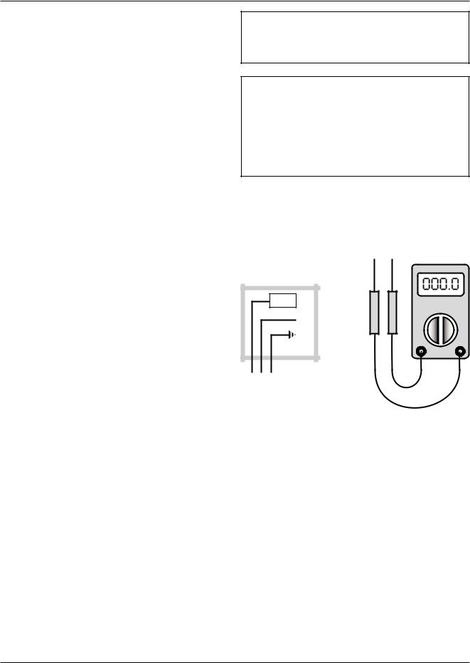
Check Your Power Source
Using a Volt-ohm meter, check the following voltages at the circuit breaker panel:
Mount the controller using the mounting bracket and appropriate hardware in four (4) places.
A minimum of eighteen (18) inches clearance from the front, and six (6) inches clearance on all other sides is required for service access. The hinged right side of the box should be installed with sufficient clearance (minimum 3” from bolt hole on the right side) to open the cover.
An electrical distribution sub-panel containing appropriate disconnect switches and surge suppressors is required at or near the equipment location(s).
Electrical Installation
Requires: 120 VAC, Draws 0.5 amp; 60 Hz.
120 VAC Feeder Circuits: Install a surge protection device sized appropriately for your installation at each module.
Install a separate disconnect means for each load. Use appropriately sized wire for equipment as defined by NEC and/or local code. All primary wiring should be no less than 125% of minimum rating.
It is strongly recommended that the controller and the boiler(s) be supplied from the same power source. Install conduit as appropriate.
BLACK CIRCUIT |
VOLT-OHM |
BREAKER |
|
|
METER |
WHITE |
|
GREEN |
|
GROUND |
|
A B C
Fig. 1: Volt-ohm Meter
AC = 108 Volts AC Minimum, 132 Volts MAX AB = 108 Volts AC Minimum, 132 Volts MAX BC = Must be less than .6 Volts AC
6
Power to the Controller
•Observe (follow proper) polarity.
•Observe proper wire colors while making electrical connections.
•Provide an external surge suppressor capable of maintaining system integrity.
•Provide overload protection and a disconnect means for equipment serviceability as required by local and state code.
•Conduit cannot be used as the ground. (There must be a “WIRED” ground.)
•Very Important: A grounding electrode conductor shall be used to connect the equipment grounding conductors, the equipment enclosures, and where the system is grounded, the grounded service conductor to the grounding electrode.
Controller field Wiring
for Single-Stage (ON/Off) Boilers
All stage connections on the control board are connected at the {TH} (Thermostat) location on the boiler wiring diagram.
for multiple-Stage Boilers
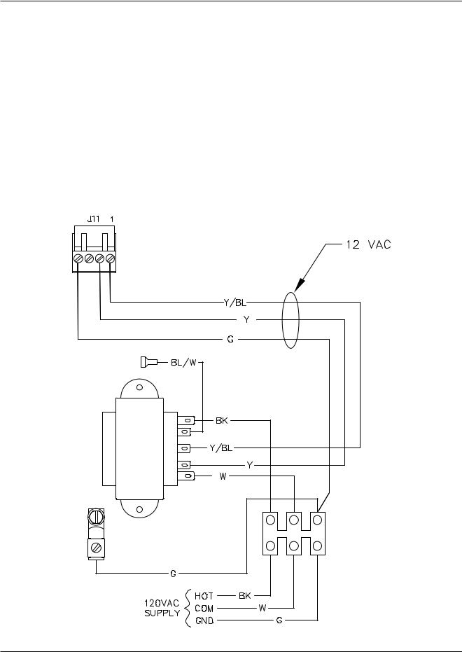
First stage connections on the control board are connected at the {TH} (Thermostat) location on the boiler wiring diagram. Second (or third, etc.) stage connections on the control board are connected at the locations shown on the boiler wiring diagram.
Fig. 2: Wiring Diagram
7
Notes:
1.Tighten terminal strip clamping screws to 2.5 inlbs. Breakage from over-torquing is not covered under warranty.
2.Use stranded copper conductors only. For supply connections, use wires sized on the basis of 60°C (140°F) ampacity and rated a minimum 90°C (194°F).
3.Install disconnect for each control unit.
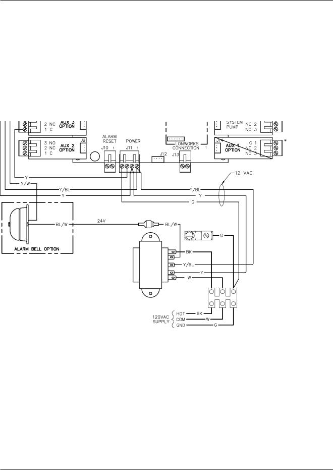
4.For external building control or thermostat control, remove wiring to J6 (CHF) connector and activate with 12 to 28 VAC.
Fig. 3: Wiring Diagram
8

Communication (RS485) Wiring Air Temperature Sensor Required for Optional Slave Installation
Unit(s)
Y-304 Slave Cable Installation from System Control module
•Y-304 slave cable or equivalent shielded communications cable (Belden #9842, Belden #8132 or Alpha 3492C) must be used. Maximum cable length 100 ft. Correct polarity must be observed. Make use of wire color coding to ensure polarity.
•The shielding [foil wrapper-bare wire (drain)] MUST be grounded. Grounding is done at the Master Y-200 Control only. DO NOT ground the shield at the slave unit end of the cable.
•Note: Equivalent shielded cable must be suitable for RS485 communication applications; must have 100-140 ohm impedance and less than 30 picofarad per foot capacitance.
•Must be installed in conduit that does not contain any other wiring.
•Port J18 (see Fig. 4) is used for the interconnection between the master controller and slave units.
•Master/Slave interconnection should be wired from Master to Slave #1, Slave #1 to Slave #2, Slave #2 to Slave #3, and Slave #3 to Slave #4.
Fig. 4: Master RS485 Communications Cable
Schematic
Fig. 5: Typical Outdoor Air Temperature Sensor
•Locate the sensor on the coldest side of building, usually the north side.
•Install the sensor in a shaded area, out of direct sunlight.
•Locate no higher than 2/3 way up the side of the building, or between the 2nd and 3rd floor if the building is more than 3 stories tall.
•Do not locate under an overhang, near wall corners, near drafts from stacks, air moving devices, windows, doors, or balconies.
•Shielded twisted pair (18 AWG) must be used for sensor connections. Polarity must be observed. Cable length shall not exceed 300 feet, and the shielding must be grounded.
•Grounding is done at the Master Y-200 control ONLY. Do Not ground the Slave units or Temperature Sensor enclosure.
•Must be installed with properly-sized conduit that contains no other wiring.
•The outdoor air temperature and water temperature sensor are identical and interchangeable.
9

Water Temperature Sensor
Installation
Hydronic Heating Applications
4 OR MORE STAGES OR
4:1 TURN DOWN OR HIGHER
5’ MAX
5’ MAX
12” MAX 
Fig. 6: Typical Water Sensor
•Hydronic installations may require outdoor reset function. See page 11 and screen 02.
•Ensure shielded cable length does not exceed 300 feet. Use 18 AWG shielded wire for sensor connections.
•Must be installed in properly-sized conduit with no other wiring.
NOTE: Piping diagrams in this manual are not intended to replace an engineered piping system.
•Locate the water sensor as shown in Fig. 6
NOTE: When the system involves a variable-speed pump, it is recommended that the temperature sensor be installed in the tee connecting boiler outlet piping to the system. This is to ensure the control can respond to the changing conditions of the system by placing the sensor as close to the blend location as possible and then provide an appropriate and measured response to maintain desired system delivery temperature.
10
Domestic Hot Water Supply
Applications
Fig. 7: Domestic Hot Water Supply
•Outdoor reset function should be disabled. See screen 06 and 24.
Power Test
Check Power
Utilizing a Volt-ohm meter (VOM) monitor the following on the controller for proper voltage levels. Check at the Terminal Block (TB-1).
From |
To |
Indication |
|
|
|
|
|
TB pin 1 |
TB pin 2 |
108 VAC to 132 |
|
VAC |
|||
|
|
||
|
|
|
|
TB pin 1 |
Single Point |
108 VAC to 132 |
|
Ground |
VAC |
||
|
|||
|
|
|
|
TB pin 2 |
Single Point |
Less than 0.6 VAC |
|
Ground |
|||
|
|
||
|
|
|
|
Table C: Voltage Measurements |
|||
11

Installation Verification
Procedure
Register
Before proceeding any further, please verify that the user registration form has been completed and mailed.
mechanical Installation
Verify that the mechanical installation has been completed in accordance with the instructions.
Outdoor Air Temperature Sensor
Verify that all Outdoor Air Temperature Sensor installation parameters have been met.
Water Temperature Sensor
Verify that the Water Temperature Sensor installation parameters have been met.
Optional Equipment
Verify that optionally ordered equipment installation parameters have been met.
System module Installation
Verify electrical power wiring connections.
Verify electrical connection torque requirements.
Verify Outdoor Air Temperature Sensor wiring.
Verify Water Temperature Sensor wiring.
Verify Power Test has been completed successfully.
CONTROLLER fAmILIARIzATION
This system is configured utilizing a LCD display (2 lines, 20 characters each) with keypad for data entry. Open the front cover of the Control Box for access to the LCD display and keypad. Open the control panel to gain access to the interface connections.
REFER TO THE TABLES ON THE FOLLOWING PAGES AND THE DISPLAY SCREENS FOR DETAILED CONFIGURATION INSTRUCTIONS.
NOTE: Controller is shipped with factory defaults. Your system may require different program settings.
12
 Loading...