


INSTALLATION & OPERATING
INSTRUCTIONS
Econopak
Water
Heaters
Models 0260–0401
Type WH
WARNING: If the information in these instructions is not followed exactly, a fire or explosion may result causing property damage, personal injury or death.
FOR YOUR SAFETY: Do not store or use gasoline or other flammable vapors and liquids in the vicinity of this or any other appliance.
WHAT TO DO IF YOU SMELL GAS:
•Do not try to light any appliance.
•Do not touch any electrical switch; do not use any phone in your building.
•Immediately call your gas supplier from a neighbor's phone. Follow the gas supplier's instructions.
•If you cannot reach your gas supplier, call the fire department.
Installation and service must be performed by a qualified installer, service agency or the gas supplier.
This manual should be maintained in legible condition and kept adjacent to the heater or in a safe place for future reference.
Catalog No. 3000.51F |
Effective: 04-08-09 |
Replaces: 03-25-08 |
P/N 240726 Rev. 7 |
Rev. 7 reflects the following: Changes to: Paragraph 3 of the GENERAL SPECIFICATIONS section on page 6; Fig. 13 on page 14; paragraph one of the Electrical Wiring section on page 16; te Wiring Diagrams on pages 17–21; the For Intermittent Ignition (IID) with Honeywell or Robertshaw Gas Valve section on pages 24 and 25; the TROUBLESHOOTING chart on page 30.
2

CONTENTS
WARNINGS |
4 |
SERVICING PROCEDURES |
22 |
Pay Attention to These Terms |
4 |
Sequence of Operation |
22 |
GENERAL SAFETY |
5 |
Start-up Procedures |
22 |
Time/Temperature Relationships in Scalds 5 |
Controls |
26 |
|
RECEIVING EQUIPMENT |
6 |
Repair Section |
28 |
GENERAL |
|
TROUBLESHOOTING |
30 |
SPECIFICATIONS |
6 |
Electrical (Electronic Ignition IID) |
32 |
INSTALLATION |
8 |
Electrical (Standing Pilot) |
33 |
Code Requirements |
8 |
ADJUSTMENTS & REPLACEMENT |
|
Mounting Base |
8 |
OF COMPONENTS |
34 |
Clearances |
8 |
WARRANTY |
36 |
Combustion & Ventilation Air |
8 |
|
|
Venting Connections |
9 |
|
|
Gas Supply Connections |
13 |
|
|
Water Connections & System Piping |
14 |
|
|
Electrical Wiring |
16 |
|
|
Wiring Diagrams |
17 |
|
|
|
|
|
|
3
WARNINGS—Pay Attention to These Terms
DANGER: Indicates the presence of immediate hazards which will cause severe personal injury, death or substantial property damage if ignored.
WARNING: Indicates the presence of hazards or unsafe practices which could cause severe personal injury, death or substantial property damage if ignored.
CAUTION: Indicates the presence of hazards or unsafe practices which could cause minor personal injury or product or property damage if ignored.
NOTE:
Indicates special instructions on installation, operation, or maintenance which are important but not related to personal injury hazards.
DANGER: Failure to install the draft hood and properly vent the water heater to the outdoors as outlined in the Venting section of this manual can result in unsafe operation of the water heater. To avoid the risk of fire, explosion, or asphyxiation from carbon monoxide, never operate this water heater unless it is properly vented and has an adequate air supply for proper operation. Be sure to inspect the vent system for proper installation at initial start-up; and at least annually thereafter. Refer to the Maintenance section of this manual for more information regarding vent system inspections.
DANGER: Water heaters utilizing Liquefied
Petroleum gas (LP) are different from natural gas models. A natural gas heater will not function safely on LP gas and vice versa. Conversion from Natural gas to LP gas (or vice versa) must be done by a qualified service technician. To avoid possible equipment damage, personal injury or fire: DO NOT connect this water heater to a fuel type not in accordance with unit data plate. Propane for propane units, Natural gas for natural gas units. These units are not certified for any other type fuel.
DANGER: LIQUEFIED PETROLEUM MODELS: Propane, or LP gas, must be used with great caution.
•It is heavier than air and will collect first in lower areas making it hard to detect at nose level.
•Make sure to look and smell for LP leaks before attempting to light appliance. Use a soapy solution to check all gas fittings and connections. Bubbling at a connection indicates a leak that must be corrected. When smelling to detect an LP leak, be sure to sniff near the floor too.
•Gas detectors are recommended in LP applications and their installation should be in accordance with the manufacturer's recommendations and/or local laws, rules, regulations or customs.
•It is recommended that more than one method be used to detect leaks in LP applications.
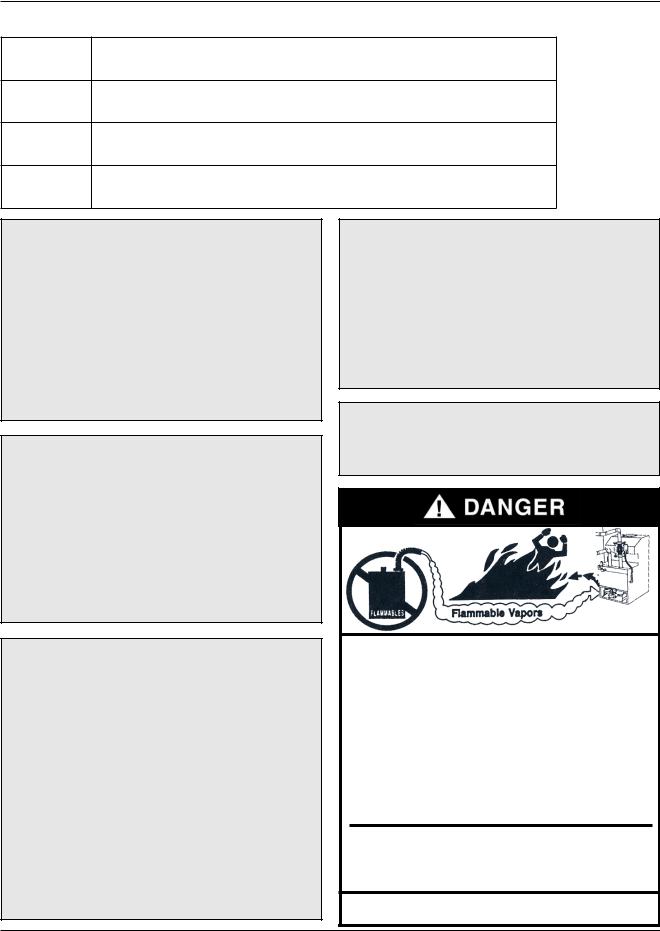
WARNING: Gasoline, as well as other flammable materials and liquids (adhesives, solvents, etc.), and the vapors they produce, are extremely dangerous. DO NOT handle, use or store gasoline or other flammable or combustible materials anywhere near or in the vicinity of a water heater. Be sure to read and follow the warning label pictured below and other labels on the water heater, as well as the warnings printed in this manual. Failure to do so can result in property damage, bodily injury, or death.
WARNING: LP appliances should not be installed below-grade (for example, in a basement) if such installation is prohibited by federal, state and/or local laws, rules, regulations or customs.
Vapors from flammable liquids will explode and catch fire causing death or severe
burns.
Do not use or store flammable products such as gasoline solvents or adhesives in the same room or area near the water heater.
Keep flammable products:
1.far away from heater,
2.in approved containers,
3.tightly closed and
4.out of childrenʼs reach.
Water heater has a main burner and pilot flame. The pilot flame:
1.is on all the time and
2.will ignite flammable vapors.
Vapors:
1.cannot be seen,
2.are heavier than air,
3.go a long way on the floor,
4.can be carried from other room to the pilot flame by their currents.
Installation: |
are at least 18" above the |
Do not install water heater |
floor. This will reduce, but |
where flammable products |
not eliminate, the risk of |
will be stored or used unless |
vapors being ignited by the |
the main burner and pilot flames |
main burner or pilot flame. |
Read and follow water heater warnings and instructions. If owners manual is missing, contact the retailer or manufacturer.
4
GENERAL SAFETY
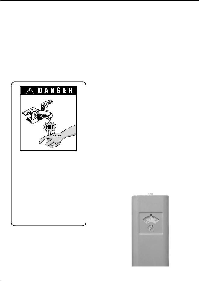
To meet commercial hot water requirements, the tankstat is adjustable up to 190°F. However, water temperatures over 125°F can cause severe burns instantly or death from scalds. This is the preferred starting point for setting the control for supplying general purpose hot water.
Safety and energy conservation are factors to be considered when setting the water temperature on the tankstat. The most energy efficient operation will result when the temperature setting is the lowest that satisfies the needs consistent with the application.
Water temperature over 125°F can cause instant severe burns or death from scalds.
Children, disabled, and elderly are at highest risk of being scalded.
See instruction manual before setting temperature at water heater.
Feel water before bathing or showering.
Temperature limiting valves are available, see manual.
Table A details the relationship of water temperature and time with regard to scald injury and may be used as a guide in determining the safest water temperature for your applications.
Temperature |
Time to Produce Serious Burn |
|
|
120°F |
More than 5 minutes |
|
|
125°F |
1-1/2 to 2 minutes |
|
|
130°F |
About 30 seconds |
|
|
135°F |
About 10 seconds |
|
|
140°F |
Less than 5 seconds |
|
|
145°F |
Less than 3 seconds |
|
|
150°F |
About 1-1/2 seconds |
|
|
155°F |
About 1 second |
|
|
Table courtesy of Shriners Burn Institute.
Table A: Time to Produce Serious Burn
Time/Temperature
Relationships in Scalds
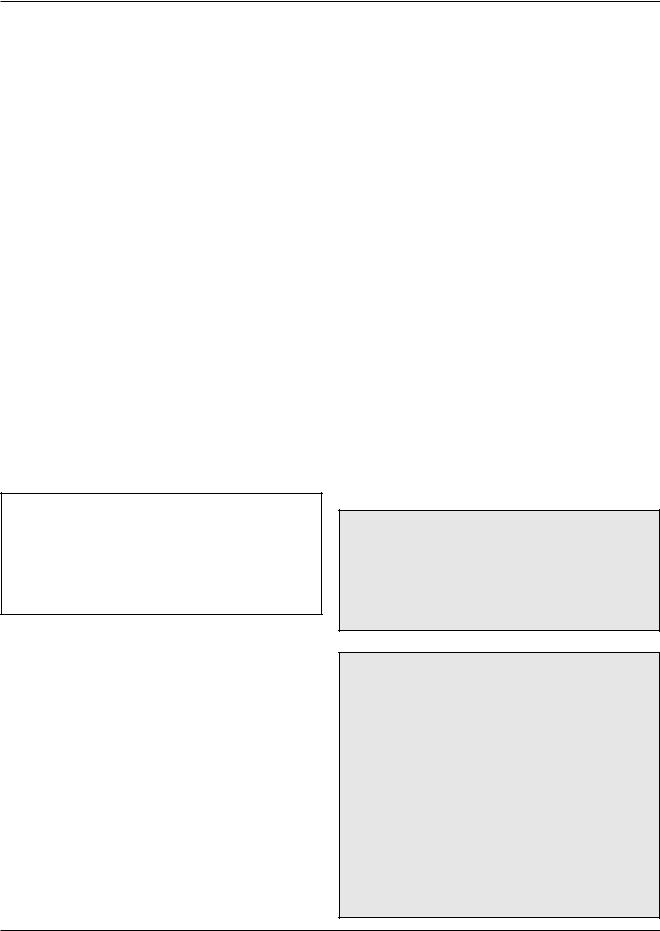
The temperature of the water in the storage tank can be regulated by setting the temperature dial on front of the tankstat. To comply with safety regulations, the tankstat was set at its lowest setting before shipment from the factory.
Fig. 1 illustrates the tankstat. To adjust the water temperature, insert a small straight screwdriver into slotted screw in hole in front of tankstat and turn wheel to desired setting. Thermostat is adjustable up to 190°F.
Maximum water temperatures occur just after burner has shut off. To find hot water temperature being delivered, turn on a hot water faucet and place a thermometer in the hot water stream and read the thermometer.
Fig. 1: Tankstat Adjustment
5

DANGER: There is a Hot Water SCALD Potential if the tankstat is set too high.
CAUTION: Hotter water increases the risk of SCALDING!
NOTE: When this heater is supplying general purpose hot water requirements for use by individuals, a thermostatically controlled mixing valve for reducing point of use water temperature is recommended to reduce the risk of scald injury. Contact a licensed plumber or the local plumbing authority for further information.
RECEIVING EQUIPMENT
On receipt of your equipment it is suggested that you visually check for external damage to the carton. If the carton is damaged, it is suggested that a note be made on the Bill of Lading when signing for equipment. Remove the heater from the carton and if it is damaged report the damage to the carrier immediately. Be sure that you receive the number of packages indicated on the Bill of Lading. Claims for shortages and damages must be filed with carrier by consignee.
Purchased parts are subject to replacement only under the manufacturer's warranty. Debits for defective replacement parts will not be accepted and defective parts will be replaced in kind only per our standard warranties.
When ordering parts, you must specify Model and Serial Number of the heater. When ordering under
warranty conditions, you must also specify date of installation.
Raypak recommends that this manual be reviewed thoroughly before installing your Raypak heater. If there are any questions which this manual does not answer, please contact your local Raypak representative.
GENERAL
SPECIFICATIONS
The Raypak water heaters are design certified by the and tested under the requirements of the American National Standard, ANSI Z21.10.3. Each heater has been constructed and pressure tested in accordance with the requirements of Section IV of the American Society of Mechanical Engineers Code, and factory fire tested.
These heaters are designed for indoor and outdoor installations, and can be installed on combustible flooring when the appropriate listed floor shield base is used.
Models are available with standing pilot or with intermittent ignition device (IID), and are equipped with the following components as standard: water circulation pump, pressure relief valve, manual reset high limit switch, flow switch, vent thermal and flame roll-out switches (except for models 330 and 400), a solid state Economaster pump control relay, 40VA transformer, and redundant combination gas valve for use with either Natural or Propane gases. A tankstat is supplied loose for installation in the field.
|
|
|
|
Piping |
Dimensions (in.)*** |
|
||||
|
|
Recovery |
|
Connections |
|
|||||
Model |
Input |
Tank |
|
|
|
|
|
|||
(gph) |
|
|
|
|
|
|
|
|||
No. |
(MBH) |
(Gal)** |
|
|
|
|
|
|
|
|
H |
G |
|
|
|
|
|
||||
Indoor* |
|
|
|
|
|
|||||
|
|
|
A |
C |
J |
|
K |
|||
|
|
|
|
(NPT) |
(NPT) |
|
||||
|
|
|
|
|
|
|
|
|
||
|
|
|
|
|
|
|
|
|
|
|
0260/0261 |
264 |
262 |
80 |
1-1/2 |
3/4 |
22-3/8 |
62-7/8 |
11-1/8 |
|
7 |
|
|
|
|
|
|
|
|
|
|
|
0330/0331 |
334 |
332 |
80 |
1-1/2 |
3/4 |
25-3/4 |
63-3/4 |
10-3/4 |
|
8 |
|
|
|
|
|
|
|
|
|
|
|
0400/0401 |
399 |
396 |
80 |
1-1/2 |
1 |
29-1/4 |
65-3/8 |
12-1/2 |
|
9 |
|
|
|
|
|
|
|
|
|
|
|
*Recovery based on manufacturer's rating. **May be used with other tank size capacity.
***Refer to Fig. 2 for dimensions.
Table B: Specifications and Dimensions
6

|
|
|
|
|
A |
11 |
|
|
|
|
2 |
|
|
|
|
|
|
6-3/4 |
|
8-1/2 |
|
|
K |
|
|
|
|
|
J |
|
|
H |
|
|
|
|
|
|
40 |
C |
|
|
|
G |
STACKLESS |
|
|
|
|
OUTDOOR TOP |
|
UP |
|
OUT |
IN |
GAS |
|
|
|
|
|
FRONT |
|||
|
|
|
|||
|
|
|
|
38 |
CONTROLS |
|
|
|
|
|
|
|
|
|
|
|
|
|
|
|
|
|
|
|
|
|
|
|
|
|
|
|
21-1/4 |
|
26-1/2 |
|
|
|
|
|
|
|
|
|
||||||||
|
|
|
|
|
|
|
ELEC |
|
|
|
|
|
|
|
|
|
|
|
||
|
|
|
|
|
|
|
|
|
|
|
|
|||||||||
|
|
|
|
|
|
|
CONN |
|
|
|
|
|
|
|
|
|
|
|
||
|
13-1/4 |
|
|
|
|
|
|
|
|
|
|
|
|
|
||||||
|
|
|
|
|
|
|
|
|
|
|
|
|
|
|||||||
|
|
|
|
|
|
|
|
|
|
|
|
|
|
|
|
|
|
|
|
|
|
|
|
|
|
|
|
|
|
|
|
|
|
|
|
|
|
|
|
|
|
|
|
|
|
|
|
|
|
|
|
|
|
|
2-1/2 |
|||||||
|
|
|
|
|
|
|
|
|
|
|
|
|
||||||||
|
OPTIONAL |
|
|
|
|
|
|
|
8 |
|
|
OUTDOOR |
||||||||
|
|
|
|
|
|
|
BASE |
|
|
|||||||||||
|
|
|
|
|
|
|
|
|
|
|
||||||||||
|
COMBUSTIBLE |
|
|
|
|
|
|
|
|
|
|
|
|
|
|
|
|
|
|
|
|
FLOOR SHIELD |
|
|
|
|
|
|
|
|
|
|
|
|
|
|
|
||||
|
|
26-1/2 |
|
|
|
|
|
|
|
|
|
|
|
A |
|
|
|
|
|
|
|
|
|
|
|
|
|
|
|
|
|
|
|
|
|
|
|||||
|
|
|
|
|
|
|
|
|
|
|
|
|
|
|
|
|
|
|
|
|
TANK
LOWER UPPER
HEATER
Components should be placed as close as possible.
Fig. 2: Dimensions and System Component Layout
7
INSTALLATION
Code Requirements
Installation must be in accordance with local codes, or, in the absence of local codes, with the latest editions of the National Fuel Gas Code, ANSI Z223.1,/NFPA 54, and the National Electrical Code, ANSI/NFPA 70. In Canada installations must conform with the current CAN/CSA B149 and the Canadian Electrical Code Part 1 CSA C22.2 No.1.
Where required by the authority having jurisdiction, the installation must conform to American Society of Mechanical Engineers Safety Code for Controls and Safety Devices for Automatically Fired Heaters, CSD- 1.
Mounting Base
This heater should be mounted on a level, non-com- bustible surface. Heater must not be installed on carpeting. This heater can be installed on a combustible surface only when the appropriate listed floor shield base is provided. An optional listed floor shield base is available for factory installation with the heater on all indoor models.
NOTE: The heater should be located in an area where water leakage will not result in damage to the area adjacent to the appliance or to the structure. When such locations cannot be avoided, it is recommended that a suitable drain pan, adequately drained, be installed under the appliance. The pan must not restrict air flow.
In addition, the heater shall be installed such that the gas ignition system components are protected from water (dripping, spraying, rain, etc.) during appliance operation and service (circulator replacement, control replacement, etc.).
Clearances
|
Minimum Distance |
Heater Side |
from Combustible |
|
Surfaces |
|
|
Floor |
Combustible* |
|
|
Front |
Alcove** |
|
|
Back |
12 in. |
|
|
Right |
12 in. |
|
|
Left |
12 in. |
|
|
Top (Indoor) |
39 in. |
|
|
Top (Outdoor) |
Unobstructed |
|
|
Flue Vent |
6 in. |
|
|
*Except for carpeted flooring, heaters are certified for installation on combustible floors, when equipped with listed floor shield base. **A front clearance of at least 24 in. is recommended for adequate service of burner-tray and controls.
Table C: Minimum Clearances from Combustible Surfaces
Combustion & Ventilation Air
(Indoor models only)
WARNING: Air supply to the heater room must not be affected by mechanical exhaust vents located in other parts of the house, such as kitchen or bathroom fans, or attic blowers. Mechanical exhaust vents may create a negative pressure condition in the heater room that can become a hazard of asphyxiation, explosion or fire.
CAUTION: Combustion air must not be contaminated by corrosive chemical fumes which can damage the heater. Measures must be taken to prevent the entry of corrosive chemical fumes to the combustion and ventilation air supply. Such chemicals include, but are not limited to, chlorinated and/or fluorinated hydrocarbons such as found in refrigerants, aerosol propellants, dry-cleaning fluids, degreasers, and paint removers. Other harmful elements may come from bleaches, air fresheners, or mastics. Vapors from these types of products can form corrosive acid compounds when burned in a gas flame. The resulting acid condensate can damage or substantially reduce the life of the heater. It may be necessary to provide outside air directly to the heater in order to avoid this problem.
8
1.The heater must be provided with adequate supply of air for proper combustion and ventilation in accordance with the latest edition of the National Fuel Gas Code, ANSI Z223.1, or applicable provisions of the local building codes.
2.When the heater is installed in a confined space where all air is supplied from inside the building, the heater room must be provided with TWO openings, each one having a minimum net free area, in square inches as shown in Table D.
Model No. |
Sq. in. of Each Free Area |
|
|
0260/0261 |
264 |
|
|
0330/0331 |
334 |
|
|
0400/0401 |
399 |
|
|
Table D: Minimum Net Free Area
One opening shall be within 12 inches of the top, and the other opening within 12 inches of the floor. If additional gas appliances are installed in the same space, the total input of all gas appliances installed in the same space, must be considered in the calculation. Refer to Sec. 5.3.5 of the latest edition of the National Fuel Gas Code for additional requirements.
NOTE: If louvers, grills or screens are used on the openings, obtain the net free area from their supplier or manufacturer. If the design free area of a louver is not known nor available, it shall be assumed that wood louvers will have 20-25 percent free area and metal louvers will have 60-75 percent free area as shown in the National Fuel Gas Code.
3.If the heater room is located against an outside wall and air openings can communicate directly with the outdoors, the TWO openings on the out side wall must each have a net free area, in square inches as shown in Table E.
sure. If horizontal ducts are used, the area must be doubled and the duct area shall not be less than the area of the openings they connect, and in no case shall the smallest dimension be less than 3 inches.
Outdoor Models
Heaters must not be installed under an overhang of less than three (3) feet from the top on the heater. Three (3) sides must be open in the area under the overhang. Roof water drainage must be diverted away from the heater installed under overhangs with the use of gutters.
The point from where the flue products exit the heater must be a minimum of four (4) feet below, four (4) feet horizontally from or one (1) foot above any door, window or gravity inlet to a building. The top surface of the heater shall be at least three (3) feet above any forced air inlet, or intake ducts located within ten (10) feet horizontally.
In areas where high winds are frequent, it may be necessary to locate the heater a minimum of three (3) feet from high vertical walls, or install a wind break so the heater is not in direct wind current.
Venting Connections
Outdoor Models
Outdoor vent top is shipped separately and must be installed on site.
Models 0260–0401
1.Insert screw retainer clip over mounting flange, (4 places).
Model No. |
Sq. in. of Each Free Area |
|
|
|
|
|
|
0260/0261 |
66 |
|
|
|
|
|
|
0330/0331 |
84 |
|
|
|
|
|
|
|
|
|
|
0400/0401 |
100 |
|
Fig. 3: Location of Mounting Clips |
|
|
|
|
|
|
|
|
Table E: Minimum Net Free Area
Location of the openings is the same as in the previous case - that is, within 12 inches of the top, and within 12 inches of the bottom of the enclo-
9
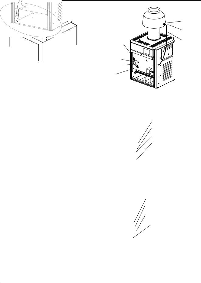
2.Attach mounting angles to heater jacket with 1/2" sheet metal screws, (4 places).
Fig. 4: Location of Mounting Angles
3.Lower outdoor top to heater and secure with 1" sheet metal screws.
|
TEMPERATURE |
|
|
SENSOR |
|
|
MOUNTING |
|
|
SCREWS (2) |
|
CONNECT ONE |
|
|
VENT SENSOR |
HARNESS |
|
WIRE TO THE |
||
ASSEMBLY |
||
HIGH LIMIT WIRE |
||
|
||
CONNECT ONE |
|
|
VENT SENSOR |
|
|
WIRE TO THE |
|
|
ROLL-OUT |
|
|
SENSOR WIRE |
|
|
WIRE FROM |
|
|
TRANSFORMER |
|
|
ROLL-OUT |
|
|
SENSOR |
|
Fig. 6: Mounting Flue Sensor
4.Remove door and locate wire from roll out sensor to Hi Limit with the male/female connector.
WIRE FROM TRANSFORMER
MALE/FEMALE
WIRE TERMINAL
WIRE FROM HIGH LIMIT
ROLL OUT SENSOR
Fig. 5: Long Side of Mounting Angle Located as Shown
Indoor Models
The drafthood is shipped separately and must be installed on the heater.
Models 0260 & 0261
1.Mount drafthood on top of heater and attach with the 4 sheet metal screws provided. Drafthood should be positioned with the vent sensor located on the front left side as shown.
2.Remove plastic plug from left side of heater jacket and install plastic grommet provided.
3.Route flue sensor wire harness through the grommet installed in Step 2.
Fig. 7: Before Installation of Drafthood
WIRE FROM TRANSFORMER
CONNECT ONE VENT SENSOR WIRE
TO HIGH LIMIT WIRE
CONNECT ONE VENT SENSOR WIRE
TO ROLL OUT SENSOR WIRE
Fig. 8: After Installation of Drafthood
5.Disconnect male/female connector and attach to the 2 wires from drafthood vent sensor harness.
10
Models 0330, 0331, 0400 & 0401
Vent Terminal/Indoor Stack Installation
1.Remove the louvered jacket top by removing four
(4) #10 flat head screws.
2.If originally installed, remove "Pagoda" top from the louvered jacket top.
3.Place the inner stack adapter panel over the flue collector inside the heater. Make sure the flanged side of the flue opening is up.
4.Turn the stack (draft hood) up side down and set it down bottom side up.
5.Turn the jacket top panel (removed in Step 1) up side down and place it through the stack.
6.Attach the three (3) mounting brackets to the stack using the screws provided and the holes that are pre-drilled in the stack. Make sure the brackets are positioned with the flange near the top side of the stack (see Fig. 9). Caution must be taken not to over tighten and strip the screw threads.
7.Turn the assembled stack and jacket top, right side up. The jacket top will be trapped between the brackets and the top of the stack. Place the stack over the inner adapter panel flanged hole and lower the louvered jacket top panel back into its original position. Reinstall the four (4) green #10 flat head screws removed in Step 1 above.
|
|
|
|
|
|
|
|
|
|
DRAFTHOOD |
SCREW HOLE |
|
|
|
|
|
|
JACKET TOP PANEL |
|||
|
|
|
|
|
|
|||||
LOCATION |
|
|
|
|
|
(part of the heater) |
||||
4-3/4" |
|
|
|
|
|
|
|
|
|
#10 SHEET METAL SCREW (3) |
|
|
|
|
|
|
|
|
|
||
|
|
|
|
|
|
|
|
|
||
|
|
|
|
|
|
|
|
|
||
|
|
|
|
|
|
|
|
|
MOUNTING BRACKET (3) |
|
|
|
|
|
|
|
|
|
|
|
|
|
|
|
|
|
|
|
|
|
|
|
|
|
|
|
|
|
|
|
|
|
INNER STACK ADAPTER PANEL |
|
|
|
|
|
|
|
|
|
|
FLUE COLLECTOR |
|
|
|
|
|
|
|
|
|
|
(part of heater) |
|
|
|
|
|
|
|
|
|
|
COMBUSTIBLE FLOOR SHIELD |
|
|
|
|
|
|
|
|
|
|
(optional for indoor) |
|
|
|
|
|
|
|
|
|
|
2-1/2" |
|
|
|
|
|
|
|
|
|
||
|
|
|
|
|
|
|
|
|
||
|
|
|
|
|
|
|
|
|||
Fig. 9: Vent Terminal/Indoor Stack Installation
WARNING: Indoor heaters require a drafthood that must be connected to a vent pipe and properly vented to the outside. Failure to follow this procedure can cause fire or fatal carbon monoxide poisoning.
Vent piping the same size or larger than the draft hood outlet is recommended, however, when the total vent height is at least ten (10) feet (draft hood relief opening to vent terminal), the vent pipe size may be reduced as specified in the National Fuel Gas Code, ANSI Z 223.1. As much as possible avoid long horizontal runs of vent pipe and too many elbows.
If installation requires horizontal runs, the vent pipe must have a minimum of 1/4 inch per foot rise and should be supported at not more than five foot intervals. Plumbers tape, crisscrossed, will serve to space both horizontal and vertical piping. Maximum vent connector horizontal length shall be 1-1/2 feet (18 inches) for each inch of connector diameter as shown in Table F.
|
Vent |
Max. |
Model No. |
Connector |
Horizontal |
|
Diameter (in.) |
Length (ft) |
|
|
|
0260/0261 |
7 |
12 |
|
|
|
0330/0331 |
8 |
13.5 |
|
|
|
0400/0401 |
9 |
15 |
|
|
|
Table F: Vent Piping Specifications
Gas vents supported only by the flashing and extending above the roof more than five feet should be securely guyed or braced to withstand snow and wind loads. We recommend use of insulated vent pipe spacer through the roofs and walls.
For protection against rain or blockage by snow, the vent pipe must terminate with a listed vent cap which complies with the local codes or, in the absence of such codes, to the latest edition of the National Fuel Gas Code, ANSI Z223.1.
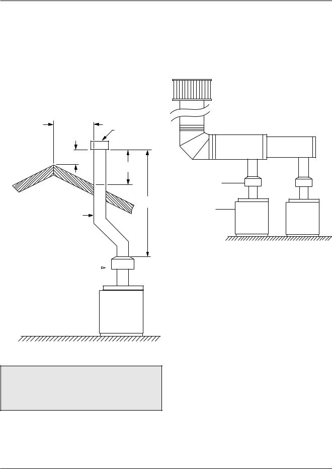
The discharge opening must be a minimum of two feet vertically from the roof surface and at least two(2) feet higher than any part of the building within ten (10) feet. Vent stack shall be at least five (5) feet in vertical height above the drafthood outlet. The vent cap location shall have a minimum clearance of four (4) feet horizontally from, and in no case above or below, unless a 4-foot horizontal distance is maintained, from electric meters, gas meters regulators and relief equipment.
11
The weight of the vent stack or chimney must not rest on heater draft hood. Support must be provided in compliance with applicable codes. The heater top and draft hood must be readily removable for maintenance and inspection. Vent pipe should be adequately supported to maintain proper clearances from combustible construction.
Type "B" double wall or equivalent vent pipe is recommended. However single wall metal vent pipe may be used as specified in the latest edition of the National Flue Gas Code ANSI Z223.1.
10' OR LESS
VENT CAP
2' MIN
2' MIN
5' MIN
VENT PIPE
Common Vents
Manifolds that connect more than one heater to a common chimney must be sized to handle the combined load. Consult available guides for proper sizing of the manifold and the chimney. At no time should the area be less than the area of the largest outlet.
Drafthood
Heater
DRAFT HOOD 
HEATER 
Fig. 10: Venting Minimum Clearances
WARNING: These heaters must not be connected into any portion of mechanical draft systems operating under positive pressure. To do so may cause the flue products to be discharged into the living space causing serious health injury.
For connections to gas vents or chimneys, vent installations shall be in accordance with Part 7, Venting of Equipment, of the National Fuel Gas Code, ANSI Z223.1, or applicable provisions of the local building codes.
Fig. 11: Common Venting
At the time of removal of an existing heater, the following steps shall be followed with each appliance remaining connected to the common venting system placed in operation, while the other appliances remaining connected to the common venting system are not in operation.
(a)Seal any unused openings in the common venting system.
(b)Visually inspect the venting system for proper size and horizontal pitch and determine there is no blockage or restriction, leakage, corrosion and other deficiencies which could cause an unsafe condition.
(c)Insofar as is practical, close all building doors and windows and all doors between the space in which the appliances remaining connected to the common venting system are located and other spaces of the building. Turn on clothes dryers and any appliance not connected to the common venting system. Turn on any exhaust fans, such as range hoods and bathroom exhausts, so they will oper-
12
 Loading...