


INSTALLATION & OPERATING
INSTRUCTIONS
2 & 4-Stage Temperature Controllers
For Raytherm™ & Hi Delta™
Boilers & Water Heaters
Catalog No. 5000.66D |
Effective: 10-11-10 |
Replaces: 05-23-08 |
P/N 241177 Rev. 5 |
Rev. 5 is a completely new edition of this manual. Please discard any previous revisions.
2
CONTENTS |
|
Introduction........................................................ |
3 |
User Interface..................................................... |
3 |
Sequence of Operation...................................... |
4 |
Installation ......................................................... |
14 |
Troubleshooting................................................. |
15 |
Electrical Wiring / Troubleshooting.................. |
17 |
Wiring Connections .......................................... |
18 |
Controller Settings............................................. |
19 |
Technical Data ................................................... |
35 |
Quick Start Set-Up & Programming Tips......... |
35 |
NOTE: Minimum 18 AWG, 105°C, stranded wire must be used for all low voltage (less than 30 volts) external connections to the unit. Solid conductors should not be used because they can cause excessive tension on contact points. Install conduit as appropriate. All high voltage wires must be the same size (105°C, stranded wire) as the ones on the unit or larger.
of applications. They can also provide sequencing with lead/lag on two boilers. The Controllers may be used to provide a setpoint temperature, outdoor reset with reset override, or dedicated domestic hot water (DHW) generation and several options for external heater control. An additional relay contact is included with the “shipped loose” version to provide an alarm signal in case of a sensor failure.
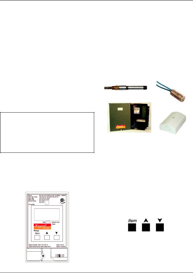
When shipped loose, this package includes:
(1) Controller in enclosure
(3) Water sensors
(1) Outdoor air sensor (optional)
(1) Well Assembly
Well Assembly
Water Sensor
Controller in |
Optional Outdoor |
Enclosure |
Air Sensor |
Fig. 2: Temp-Tracker Controller Kit (shipped loose)
INTRODUCTION
The Temp-Tracker 2-stage and 4-stage temperature controllers (Controller) are designed to be mounted on heaters with two or four stages of operation in order to provide accurate water temperature control in a variety
Fig. 1: Temp-Tracker Controller
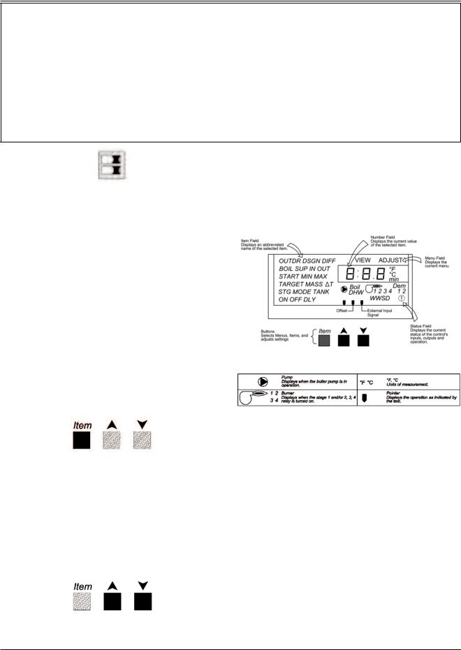
USER INTERFACE
The Controller uses a Liquid Crystal Display (LCD) as a method of supplying information. Use the LCD to setup and monitor the operation of your system. The
Controller uses three push buttons (Item, ▲, ▼) for selecting and adjusting the settings (see Fig. 3). As you program your Controller, record your settings in the actual settings columns of the Adjust menu in tables G & H, found on pages 20 & 21.
Fig. 3: Controller Push Buttons
Menu
All of the items displayed by the Controller are organized into two menus. These menus are listed on the upper right-hand side of the display (Menu Field). The default menu for Controller is the View menu. While in
3
DIP Switch Settings
(DIP package located under cover on front of PCB)
SWITCHES |
FACTORY (Default) |
Two-Stage |
|
(A) Heater Outlet Maximum: 200ºF (On) / 235ºF Heater (Off) |
235ºF Heater (Off) |
(B) Heater Plant: Two Single-Stage (On) / One Two-Stage (Off) |
One Two-Stage (Off) |
Four-Stage |
|
(A) Heater Outlet Maximum: 200ºF (On) / 235ºF Heater (Off) |
235ºF Heater (Off) |
(B) Heater Plant: Two Two-Stage (On) / One Four-Stage (Off) |
One Four-Stage (Off) |
B |
OFF |
A |
OFF |
Fig. 4: DIP Switches
(Default shown)
the View menu, the View segment is displayed. To select the Adjust menu, press and hold all three buttons simultaneously for one second (see Fig. 3). The display then advances to the Adjust menu and the Adjust segment is turned on in the display. The display will automatically revert back to the View menu after 20 seconds of keypad inactivity. Once in a menu, there will be a group of items that can be viewed within that menu.
Item
The abbreviated name of the selected item will be displayed in the item field of the display. To view the next available item in a menu, press and release the Item button. The display will return to the first item in the selected menu (see Fig. 5).
Fig. 5: Item Button
Adjust
To make an adjustment to a setting in the Controller, begin by selecting the Adjust menu by pressing and holding simultaneously all three buttons for one second, and then selecting the desired item using the Item button. Finally, use the ▲ or ▼ button to make the adjustment (see Fig. 6).
Additional information can be gained by observing the Status field of the LCD. The status field will indicate which of the Controller’s outputs are currently active. Most symbols in the status are only visible when the View menu is selected.
Display
Fig. 7: Display
Fig. 8: Symbol Description
SEqUENCE OF
OPERATION
General
Powering up the Controller
When the Controller is powered up, it turns on all segments in the display for two seconds. Next, the software version is displayed for two seconds. Finally, the Controller enters into the normal operating mode.
|
Display Backlight |
Fig. 6: Adjust Buttons |
The control’s display has a backlight that is perma- |
|
nently on while the control is powered. |
4
Primary/Secondary Piping
In primary/secondary applications, the heater outlet temperature is typically higher than the system loop temperature. Therefore, the Controller uses an additional sensor (called the system sensor) to measure the temperature in the system. The operating sensor in primary / secondary piping applications is the system sensor. See Fig. 9.
Modes of Operation (Mode)
NOTE: Mode of operation MUST be programmed into the Controller. See Figs. 21 through 25 on the following pages.
The Controller allows for eight modes of operation in order to define the Controller operation and piping arrangement used. The piping arrangement can be categorized into primary or primary/secondary. The mode of operation is selected using the MODE item in the adjust menu. The operating sensor measures the temperature being controlled out to the heating system.
The piping arrangement determines which sensor the Controller uses as the operating sensor. The operating sensor is either the heater outlet sensor or the system sensor.
It is up to the designer to determine the necessary components for and the configuration of the particular system being designed, including additional equipment, isolation relays (for loads greater than the Controller’s specified output rating), and any safety devices which in the judgment of the designer are appropriate, in order to properly size, configure and design that system and to ensure compliance with building and safety code requirements.
Typically, Raypak recommends Mode 2 for primary/secondary hydronics, Mode 3 for domestic hot water and Mode 5 for primary/secondary hydronics using outdoor reset.
NOTE: The illustrations for each mode are only mechanical concept drawings; they are not intended to describe a complete system, nor any particular system. Consult the factory for piping arrangements not depicted here.
Two Setpoints Operation, Primary Piping
Mode 1 (MODE = 1)
(Not Supported)
Mode 1 is designed for setpoint operation using Primary Piping. Once a Call for Heat (CFH) is present, the control stages the heater to maintain the heater target 1 at the heater outlet sensor. Once an indirect DHW override is present, the control stages the heater to maintain the heater target 2 at the heater outlet sensor. If both demands are present at the same time, the control operates at the higher of the two targets.
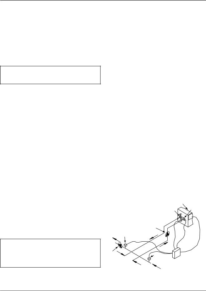
Two Setpoints with Primary/Secondary Piping
Mode 2 (Mode = 2)
Mode 2 is designed for setpoint operation using Primary/Secondary piping (see Fig. 9). A CFH is available to activate a setpoint for space heating. An indirect DHW override is available to activate a second setpoint for heating an indirect domestic hot water tank.
Once a CFH is present, the control stages the heater to maintain the heater target 1 at the heater supply sensor. Once an indirect DHW override is present, the control stages the heater to maintain the heater target
2 at the heater system sensor. If both demands are present, the control operates at the higher of the two targets.
Mode 2 requires the use of three water sensors. The inlet water sensor is located in the inlet side of the in/out header. The outlet sensor is located in the outlet side of the in/out header. The system sensor (terminals 6 and 4) must be located as shown in Fig. 9.
|
|
OPTIONAL INTEGRAL PUMP |
|
|
|
BOIL OUT SENSOR |
BOIL IN SENSOR |
|
|
|
|
|
|
PUMP LOCATION |
|
|
|
ON MODELS WITHOUT |
|
|
ALTERNATE |
INTEGRAL PUMP |
|
|
SENSOR |
|
|
|
LOCATION |
|
|
|
4 OR MORE |
|
|
|
STAGES |
|
|
SYSTEM |
|
|
|
SUPPLY |
|
|
|
MAIN |
|
|
|
SYSTEM |
|
|
|
PUMP |
|
SYSTEM SENSOR |
|
(BY OTHERS) |
* |
|
RAYPAK TEMPERATURE |
|
|
||
|
|
|
CONTOLLER |
|
|
SYSTEM RETURN |
|
*MAXIMUM 4 TIMES THE PIPE DIAMETER OR 12”, WHICHEVER IS LESS.
Fig. 9: Primary/Secondary Piping (Mode 2)
5
Domestic Hot Water Operation,
Uni-Temp 80 Piping (Mode 3)
Mode 3 is designed for dedicated DHW operation using Unitemp 80 piping. The Controller operates the heater to maintain a tank temperature at the system sensor.
Mode 3 requires the use of three water sensors. The inlet water sensor is located in the inlet side of the in/out header and the outlet sensor is located in the outlet side of the in/out header. The system sensor (terminals 6 and 4) must be located in the storage tank, as shown in Fig. 10.
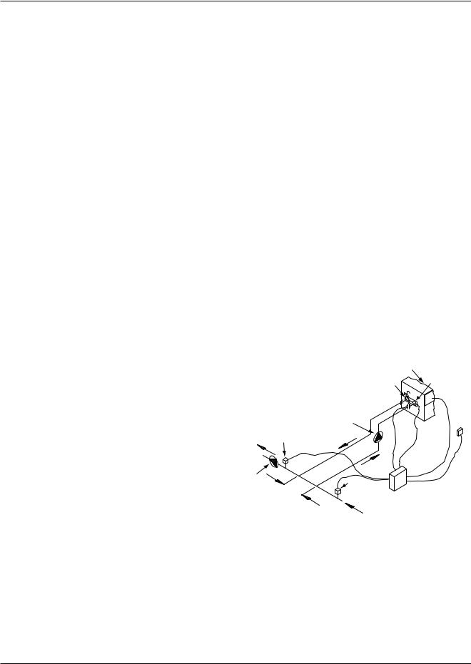
Outdoor Reset and Override Operation with Primary/Secondary Piping
Mode 5 (Mode = 5)
Mode 5 is designed for outdoor reset and override operation using Primary /Secondary Piping. The CFH is available to provide outdoor reset for hydronic heating systems. The override can be used to heat an indirect domestic hot water tank.
Once a CFH is present, the control stages the heater to maintain the calculated outdoor reset target at the heater system sensor. Once an indirect DHW override is present, the control stages the heater to maintain the heater target 2 at the heater system sensor. If both demands are present at the same time, the control operates at the higher of the two targets.
Mode 5 requires the use of three water sensors and one air sensor. The inlet water sensor is located in the inlet side of the in/out header. The outlet sensor is located in the outlet side of the in/out header. The system sensor (terminals 6 and 4) must be located on the system supply pipe, as shown in Fig. 11.
The outdoor air sensor must be located on the coldest side of the building in a shaded area out of direct sunlight.
Fig. 10: Uni-Temp 80 Piping (Mode 3)
Outdoor Reset and Override Operation with Primary Piping
Mode 4 (Mode = 4) (Not Supported)
Mode 4 is designed for outdoor reset and override operation using Primary Piping. Once a CFH is present, the control stages the heater to maintain the calculated outdoor reset target at the heater outlet sensor. Once an indirect DWH override is present, the control stages the heater to maintain the heater target 2 at the heater outlet sensor. If both demands are present at the same time, the control operates at the higher of the two targets.
|
|
OPTIONAL INTEGRAL PUMP |
|
|
|
BOIL OUT SENSOR |
BOIL IN SENSOR |
|
|
|
|
|
|
PUMP LOCATION |
OUTDOOR |
|
|
ON MODELS WITHOUT |
|
|
|
AIR |
|
|
ALTERNATE |
INTEGRAL PUMP |
|
|
SENSOR |
||
|
SENSOR |
|
|
|
LOCATION |
|
|
|
4 OR MORE |
|
|
|
STAGES |
|
|
SYSTEM |
|
|
|
SUPPLY |
|
|
|
MAIN |
|
|
|
SYSTEM |
|
|
|
PUMP |
|
SYSTEM SENSOR |
|
(BY OTHERS) |
* |
|
RAYPAK TEMPERATURE |
|
|
||
|
|
|
CONTOLLER |
|
|
SYSTEM RETURN |
|
*MAXIMUM 4 TIMES THE PIPE DIAMETER OR 12”, WHICHEVER IS LESS. |
|
||
Fig. 11: Primary/Secondary Piping with Outdoor Reset (Mode 5)
6

External Target Temperature Input and Override with Primary Piping
Mode 6 (Mode = 6) (Not Supported)
Mode 6 is designed for a 0-10VDC or a 4-20 mA external input signal and override operation using Primary Piping. The external input signal creates an internal CFH and changes the heater target according to a linear scale. The control stages the heater to maintain the heater target at the heater outlet sensor.
External Target Temperature Input and Override with Primary/Secondary Piping Mode 7 (Mode = 7)
Mode 7 is designed for a 0-10VDC external input signal and override operation using Primary/Secondary
Piping. The external input signal can be provided from a Building Management System. The override can be used to heat an indirect domestic hot water tank.
The external input signal creates an internal CFH and changes the heater target according to a linear scale. The control stages the heater to maintain the heater target at the heater outlet sensor.
Once an indirect DHW override is present, the control stages the heater to maintain the heater target at the heater system sensor. If both an external input signal and an indirect DHW override are present at the same time, the control operates at the higher of the two targets.
NOTE: To convert a 0-20 mA input signal to 0-10
VDC, a 500 Ω resistor must be added. See Fig. 13.
|
500 Ω |
|
500 Ω |
GND |
HOT |
GND |
HOT |
|
0-20 |
|
0-20 |
mA INPUT |
mA INPUT |
||
Fig. 13: 500 Ω Resistor for 4-20 mA Operation
External Direct Drive Operation
Mode 8 (Mode = 8)
Mode 8 is designed for a 0-10VDC or a 4-20 mA external input signal from a building management system or external sequence, such as the Raypak Temp-
Tracker Mod+ Hybrid, to drive the staging rate directly with either Primary or Primary/Secondary piping. The indirect DHW override is disabled.
The control receives a CFH and analog signal provided from an external control. The control stages the heater according to the input signal. The maximum outlet temperature is controlled by DIP switch “A.”
Fixed Heater Outlet Maximum: 200°F (“A” = “ON”) 235°F (“A” = “OFF”)
Fig. 12: External Input Target Temperature and Setpoint
Operation, Primary-Secondary Piping (Mode 7)
Fig. 14: External Direct Drive Operation (Mode 8)
7
Code Descriptions
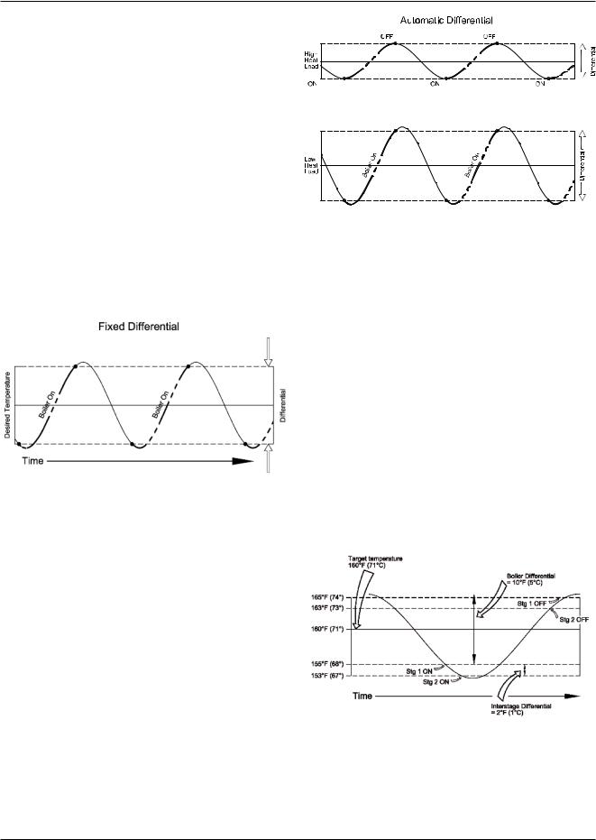
Heater Differential (DIFF)
A heat source must be operated with a differential in order to prevent short cycling. The heater differential is divided around the heater target temperature. The first-stage contact will close when the water temperature at the operating sensor is 1/2 of the differential setting below the heater target temperature, and will open when the water temperature at the operating sensor is 1/2 of the differential setting above the heater target temperature. The remaining stages will operate sequentially based on the staging mode selected.
Manual Differential
The differential can be manually set using the DIFF setting in the Adjust menu.
Fig. 15: Fixed Differential
Auto Differential
Auto Differential is only available when using PID staging.
If Auto Differential is selected, the control automatically determines the best differential as the load changes, thereby improving efficiency. During light loads, the differential is increased to allow longer on and off times to reduce the potential for short-cycling. During large loads, the differential is narrowed thereby improving comfort in heating spaces by reducing temperature swing.
Fig. 16: Auto Differential
Staging Mode (STGMODE)
The Controller can operate up to four stages in order to supply the required target temperature. The method of staging used by the Controller is either P (proportional) or PID (proportional, integral & derivative), and is selected using the STGMODE item in the adjust menu.
Proportional (P)
Proportional staging is based on manually-adjusted settings that determine when the next stage is required to turn on. These manual settings are based on temperature and time. The interstage differential sets the temperature drop at which the next stage turns on. However, in order for a stage to fire, both the “interstage delay on” and “minimum off” times must first elapse.
Fig. 17: Proportional Staging
8

Interstage Differential (STG DIFF)
The “interstage differential” is the temperature drop at which the next stage will turn on. Once a stage turns on, the next stage cannot turn on until the temperature drops the “interstage differential” below the temperature at which the previous stage turned on. The “interstage differential” is adjustable through the STG DIFF setting in the adjust menu.
Interstage Delay On (ON DLY)
The “interstage delay on” is the amount of time that must elapse before turning on the next stage. Once a stage turns on, the next stage cannot turn on until the interstage delay on time elapses. The interstage delay on is adjustable through the ON DLY setting in the adjust menu.
Interstage Delay Off (OFF DLY)
The “interstage delay off” is the amount of time that must elapse before turning off the next stage. Once a stage turns off, the next stage cannot turn off until the interstage delay off time elapses. The interstage delay off is adjustable through the OFF DLY setting in the adjust menu.
Minimum On Time (MIN ON)
The “minimum on” time is the minimum amount of time that a stage must be on before it is allowed to turn off. Once a stage turns on, the next stage cannot turn off until minimum on time elapses. The minimum on time is adjustable through the MIN ON setting in the Adjust menu.
Minimum Off Time (MIN OFF)
The “minimum off” time is the minimum amount of time that a stage must be off before it is allowed to turn on. Once a stage turns off, it cannot turn on until minimum off time elapses. The minimum off time is adjustable through the MIN OFF setting in the adjust menu.
Proportional, Integral & Derivative (PID)
PID staging allows the Controller to determine when the next stage is required to turn on or off. The
Controller automatically determines the settings that are manually selected in the proportional mode.
After each stage is turned on in the firing sequence, the Controller waits a minimum amount of time before turning on the next stage. After the minimum time delay between stages has passed, the Controller examines the control error to determine when the next stage is to fire. The control error is determined using PID logic.
Proportional compares the actual operating sensor temperature to the heater target temperature. The colder the temperature, the sooner the next stage is turned on.
Integral compares the operating sensor temperature offset (error) to the heater target temperature over a period of time.
Derivative determines how fast or slow the operating sensor temperature is changing. If the temperature is increasing slowly, the next stage is turned sooner. If the temperature is increasing quickly, the next stage is turned on later, if at all.
Heater Mass (BOIL MASS)
The heater mass setting (1, 2 or 3) allows the installer to adjust the Controller to the thermal mass of different types of heat sources used. The heater mass setting automatically determines the interstage differential, interstage delay on, interstage delay off, minimum on time and minimum off time of the stages when PID staging is used. A higher thermal mass setting provides slower staging, while a lower thermal mass provides faster staging.
Heater Mass Definitions
Mass 1 Low Volume, High Recovery
Mass 2 Medium Volume, Medium Recovery
Mass 3 High Volume Low Recovery
Table A: Heater Mass Definitions
NOTE: Always use a heater mass setting of 1 for
Raypak equipment. If the Controller continues to stage too rapidly, contact Raypak.
9
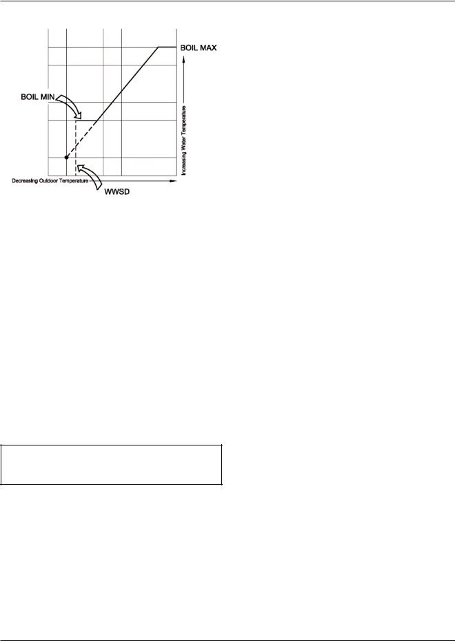
Fig. 18: Warm Weather Shutdown
Heater Minimum (BOIL MIN)
The BOIL MIN is the lowest water temperature that the Controller is allowed to use as a heater target temperature (e.g. 120 ºF). During mild conditions, if the Controller calculates a heater target temperature that is below the BOIL MIN setting, the heater target temperature is adjusted to at least the BOIL MIN setting.
During this condition, if the heater is operating, the MIN segment turns on in the LCD while the heater target temperature or heater operating sensor temperature is viewed.
Additional plumbing and/or controls may be required to maintain the heater at or above its minimum inlet temperature.
NOTE: If the installed heater is designed to operate at a target temperature less than 80°F, set the BOIL MIN adjustments to OFF.
Heater Maximum (BOIL MAX)
The BOIL MAX is the highest water temperature that the Controller is allowed to use as a heater target temperature. If the Controller does target BOIL MAX, and the heater outlet sensor is near the BOIL MAX temperature, the MAX segment turns on in the LCD while the heater target, heater inlet, heater outlet or heater supply temperature is viewed.
Heater Target Temperature (BOIL
TARGET)
The heater target temperature is determined from the mode of operation and type of demand applied. The Controller displays the temperature that it is currently trying to maintain at the operating sensor as BOIL TARGET in the view menu.
The operating sensor for modes 2, 3, 5 and 7 is the system sensor. If the Controller is not presently enabled for heat, it displays “- - -“ in the LCD. In Mode 8, no heater target temperature is generated.
System Pump Operation
The pump contacts operate when:
•A CFH is present based on the tank sensor for dedicated DHW operation (Mode 3).
•While the heater is firing and Primary/Secondary piping (Mode 2, 5, or 7) is used. Primary/ Secondary piping reduces standby losses by isolating the heater from the system while the heater is off.
•During external direct drive operation (Mode 8), the pump contact closes whenever there is an internal CFH.
•After the system shuts off the pump remains on for a few minutes to purge heat from the heater to the system.
System Pump Purge (DLY)
The controller operates the system pump based on the Pump DLY setting. Once the system shuts down, the controller keeps the system pump running for the time selected.
When Pump DLY is set to OFF, there is no purging.
When Pump DLY is set to ON, the system pump runs continuously. When on is selected and the control is configured for outdoor reset, the system pump continues to run even during Warm Weather Shut Down
(Mode 5).
10
Pump Exercising
If the system pump has not operated at least once every 70 hours, the control turns on the output for 10 seconds. This minimizes the possibility of the pump seizing during a long period of inactivity.
Setpoint Operation
A setpoint is a fixed water temperature target that the heater is to maintain at the system sensor. The heater maintains the heater target by operating the stages using the proportional or the PID logic together with the heater differential. The setpoint temperature is set using the BOIL TARGET item in the adjust menu.
Mode 2 and Enable (Dem 1)
A call for heat (CFH) is required whenever heat is required for the primary heating load. This CFH is generated when 24VAC is applied across the enable/disable connection P1 (terminals 1 and 2). Once the voltage is applied, the control turns on the Dem 1 segment in the display and the controller operates the heater stages to maintain the BOIL TARGET
1 at the system sensor.
Mode 2, 5 and 7, and Domestic Hot Water Override (Dem 2)
A CFH is required whenever heat is required for the secondary heating load such as an indirect domestic hot water tank. A CFH is generated when 24VAC is applied across the DHW contacts P1 (terminals 1 and 3). Once the voltage is applied, the control turns on the Dem 2 segment in the display and the controller operates the heater stages to maintain the BOIL TARGET
2 at the system sensor.
Dedicated Domestic Hot Water
(DHW) Operation
When mode 3 is selected, the Controller provides dedicated DHW operation.
WARNING: Verify closure across Enable/Disable contacts P1, terminals 1 and 2. DO NOT use DHW override on terminal 3.
Internal DHW Demand
A sensor is required to be installed in the tank and connected to the Com and the Sys/D terminals (6 and 4). A CFH for DHW is generated when the temperature at the DHW sensor drops 1/2 of the tank differential setting below the desired DHW tank temperature. The TANK TARGET setting is used to set the desired DHW tank temperature. Once a CFH is generated, the Dem segment turns on in the LCD.
The Controller then operates the heater stages to maintain the programmed heater target temperature at the heater system sensor located in the tank. The heater target temperature is set using the BOIL TARGET item in the adjust menu.
Tank Differential (TANK DIFF)
A differential setting that operates 1/2 above and below the TANK TARGET is selectable using the TANK DIFF item in the adjust menu.
Outdoor Reset Operation
When Mode 5 is selected, the Controller uses outdoor reset to control the water temperature. Outdoor reset adjusts the target temperature based on the outdoor air temperature and the reset ratio; as the outdoor air temperature rises, the need for heat drops and the setpoint is reduced The reset ratio is determined from the Heater Start, Heater Design, Outdoor Start and Outdoor Design settings.
Enable/Disable
A CFH is generated when a voltage of 24 VAC is applied across the Enable/Disable terminals (1 and 2).
Once voltage is applied, the Controller turns on the Dem 1 segment in the display. If the Controller is not in Warm Weather Shut Down (WWSD), it then operates the heater stages to maintain the heater target temperature.
NOTE: If the controller is in WWSD, the WWSD segment is shown in the display and the heater target in the view menu of the display remains “ - - - “ (no target).
11
 Loading...