


Raypak P-R185B, RP2100, C-R185B, P-R185BL, C-R185BL User Manual
...
INSTALLATION AND OPERATING INSTRUCTIONS
RP2100
SWIMMING POOL and
SPA HEATER
Atmospheric Models
P-R185B to P-R405B
C-R185B to C-R405B
Low NOx Models
P-R185BL to P-R405BL C-R185BL to C-R405BL
CATALOG NO. 6000.52-AK
Effective: 05-01-04
Replaces: 03-15-04
Fig.# 9478
WARNING: If the information in these instructions is not followed exactly, a fire or explosion may result causing property damage, personal injury or death.
—Do not store or use gasoline or other flammable vapors and liquids in the vicinity of this or any other appliance.
—WHAT TO DO IF YOU SMELL GAS
•Do not try to light any appliance.
•Do not touch any electrical switch; do not use any phone in your building.
•Immediately call your gas supplier from a neighbor's phone. Follow the gas supplier's instructions.
•If you cannot reach your gas supplier, call the fire department.
—Installation and service must be performed by a qualified installer, service agency or the gas supplier.
This manual should be maintained in legible condition and kept adjacent to the heater or kept in a safe place for future reference.
Part No. 240612

CONTENTS
4PARTONE
OWNER'SOPERATINGINSTRUCTIONS
4SECTION 1
START-UPPROCEDURES
4BeforeStart-Up
5Lighting Instructions & Shut-Off Procedures-
Manually Lighted Pilots MV
6Operating Instruction & Shut-Off Procedures-
Automatically Lighted Pilots IID
7After Start-Up
7SECTION 2 CAUTION
7SECTION 3
MAINTENANCE&CAREPROCEDURES
8Pool & Spa Water Chemistry
8Cold Weather Operation
9Winterizing the Pool & Spa Heater
10PART TWO
INSTALLATION&SERVICE INSTRUCTIONS
10SECTION 1
RECEIVINGEQUIPMENT
10SECTION 2
GENERALSPECIFICATIONS
11SECTION 3
INSTALLATIONINSTRUCTIONS
11 CodeRequirements
11Clearances
12Outdoor Heater Installation
12 |
Indoor Heater Installation |
16 |
Specifications and Dimensions |
16Combustion Air
17Vent Piping
17 Gas Supply Connections
19 Plumbing For Water Connections
23Heat Exchanger Reversal Procedure
24Electrical Wiring
25TransformerWiring
26Wiring Diagram-Millivolt (Mechanical Therm.)
27Wiring Diagram-IID (Atmospheric)
28Wiring Diagram-IID (Low NOx)
29SECTION 4
SERVICINGINSTRUCTIONS
29 |
General Location of Controls |
29Millivolt Controls
30Digital Thermostat Controls
31Digital Diagnostics and Codes
32Remote Control and Operation Installation
34Pressure Switch
34Flame Roll-Out Safety Switch
34High Limit
34Pilot Safety
35 |
BurnerDrawerRemoval |
35 |
GasValveRemoval |
35 |
Main Burner and Orifice Removal |
35 |
Pilot Removal and Cleaning |
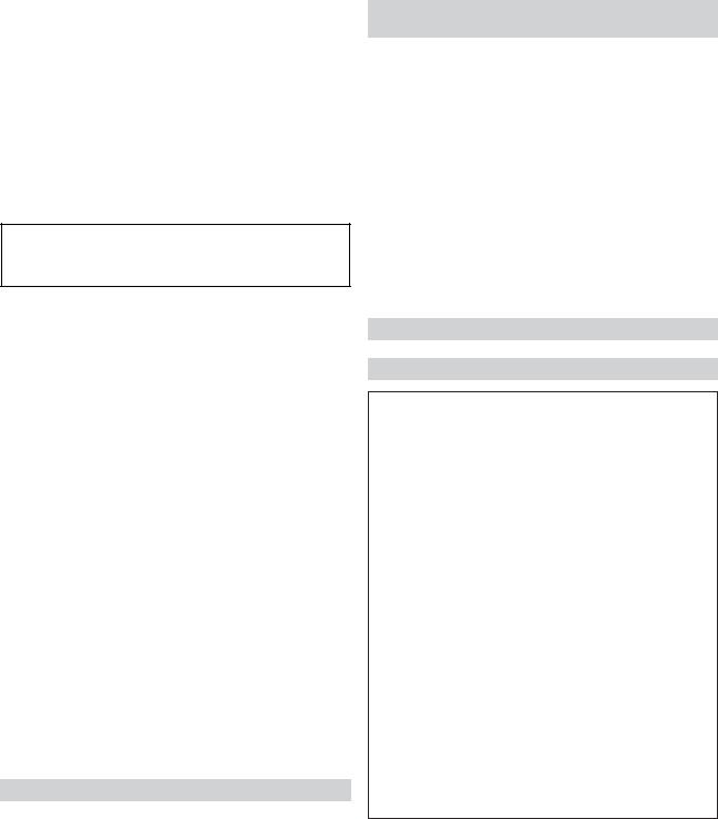
35Heat Exchanger Removal
36TubeCleaningProcedure
36 |
DesootingProcedure |
36 |
CombustionChamberRemoval |
36 |
Immersion Well Replacement |
36Unitherm Governor (U.G.) Replacement
37Low NOx Pool Heaters
39SECTION 5
TROUBLESHOOTINGGUIDE
39Mechanical
40Electrical MV Units
41Electrical IID Units
42Digital Control Logic
43SECTION 6 REPLACEMENTPARTS
44Illustrated Parts List
46 Part Numbers
3
PART ONE
OWNER'SOPERATINGINSTRUCTIONS
FOR YOUR SAFETYREAD BEFORE OPERATING
WARNING: IF YOU DO NOT FOLLOW THESE INSTRUCTIONS EXACTLY, A FIRE OR EXPLOSION MAY RESULT, CAUSING PROPERTY DAMAGE, PERSONAL INJURY OR LOSS OF LIFE.
SECTION 1 - START-UP PROCEDURES
Your Raypak Pool/Spa heater has been designed for years of safe and reliable pool/spa water heating. It is available in millivolt or electronic control options. ASME certified units, typical used in commercial applications, are also available. This manual provides operation, installation, maintenance, and service information for these heaters.
ON
OFF
Fig.# 9472
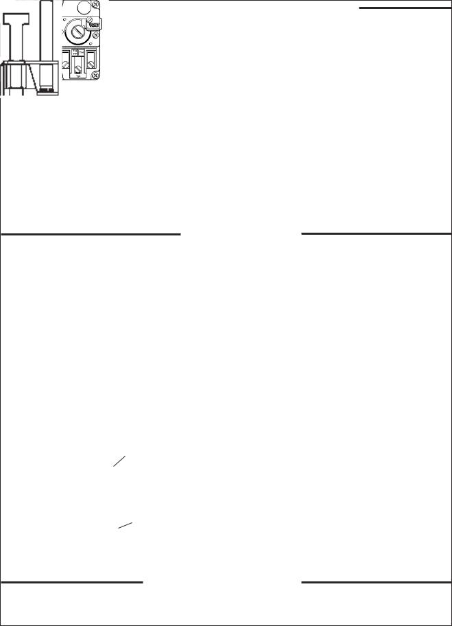
If your heater has been installed correctly, operating the heater is an easy task. The upper front panel of the heater contains the control center that allows you to turn the heater on or off and adjust the temperature settings for the pool or spa. The temperature range is factory set from 65°F (18°C) to 104°F (40°C). The heater is also equipped with a toggle switch to turn the heater on and off, see fig. # 9472 above for location. Section 4 of this manual contains more details about the use of the controls in the Controls Adjustments subsection (page 29).
BEFORESTART-UP
BURNERS |
|
WATER |
Clean main burners, combustion fan and air louvers of |
|
Water must be flowing through the heater during opera- |
dust,lintanddebris. Keepheaterareaclearandfreefrom |
tion. Insurethatsystemisfilledwithwaterandhavepump |
|
combustibles, flammable liquids and chemicals. Do not |
operating. |
|
obstruct the flow of combustion and ventilating air. |
|
|
Fig.# 9478
RP2100 DIGITAL IID POLYMER
4
CAUTION: Propane gas is heavier than air and will settle on the ground. Since propane can accumulate in confined areas, extra care should be exercised when lighting propane heaters.
LIGHTING INSTRUCTIONS AND SHUT-OFF PROCEDURES
MANUALLY LIGHTED PILOTS
MILLIVOLT SYSTEM
A.This appliance has a pilot that must be lit by hand. When lighting the pilot, follow these instructions exactly.
B.BEFORE LIGHTING smell all around the appliance area for gas. Be sure to smell next to the floor because some gas is heavier than air and will settle on the floor.
WHAT TO DO IF YOU SMELL GAS:
*Do not try to light any appliance.
*Do not touch any electric switch; do not use any phone in your building.
*Immediately call your gas supplier from a neighbor's phone. Follow the gas supplier's instructions.
*If you cannot reach your gas supplier, call the fire department.
C.Use only your hand to push in or turn the gas control knob. Never use tools. If the knob will not push in or turn by hand, do not try to repair it. Call a qualified service technician. Force or attempted repair may result in a fire or explosion.
D.Do not use this appliance if any part has been under water. Immediately call a qualified service technician to inspect the appliance and to replace any part of the control system and any gas control which has been under water.
LIGHTING INSTRUCTIONS
1.STOP! Read the safety information above.
2.Set the thermostat on the lowest setting.
3.Turn On/Off switch to the "Off" position.
4.Remove heater door panel.
5.Push in gas control knob slightly and turn clockwise  to "Off".
NOTE: Knob cannot be turned from "Pilot" to Off" unless knob is pushed in slightly. Do not force.
6.Wait 5 minutes to clear out any gas. If you then smell gas, STOP! Follow "B" in the safety information above. If you don't smell gas, go to the next step.
7.Locate pilot mounted on the right side panel of the burner drawer. For burner drawer location, see location of control section, page 20.
GAS CONTROL KNOB SHOWN IN OFF POSITION
HONEYWELL
GAS VALVE
MILLIVOLT
ROBERTSHAW
Fig. # 8081.0 GAS VALVE
MILLIVOLT
HONEYWELL PILOT |
ROBERTSHAW PILOT |
Fig. # 8083.0 |
Fig. # 8084.1 |
8.Turn knob on gas control counter-clockwise
 to "Pilot"
9.Place flame to end of pilot tube. Push in control knob all the way and hold to light pilot. Continue to hold control knob in for about one minute after the pilot is lighted, release knob and it will pop back up. Pilot should remain lighted. If it goes out, repeat steps 5 through 9. *If knob does not pop up when released, stop and immediately call your service technician or gas supplier.
10.Stand to the side of the heater and turn the gas control knob counter clockwise to  "On".
"On".
11.Replace heater door panel.
12.Turn On/Off switch to the "On" position.
13.Set thermostat to the desired setting.
Fig. # 8079.0
TO TURN OFF GAS TO APPLIANCE
1.Set the thermostat to the lowest setting.
2.Turn On/Off switch to the "Off" position.
3.Remove heater door panel.
4.Push the gas control knob slightly and turn clockwise to  "Off". Do not force.
5.Replace heater door panel.
5
CAUTION: Propane gas is heavier than air and will settle on the ground. Since propane can accumulate in confined areas, extra care should be exercised when lighting propane heaters.
OPERATING INSTRUCTIONS AND SHUT-OFF PROCEDURES
AUTOMATICALLY LIGHTED PILOTS
ELECTRONIC IGNITIONS SYSTEMS
A. |
This appliance is equipped with an ignition |
|
*If you cannot reach your gas supplier, call the fire |
|||
|
device which automatically lights the pilot. Do |
|
department. |
|||
|
not try to light the pilot by hand. |
|
|
|
|
|
B. |
BEFORE OPERATING, smell all around the |
|
C. Use only your hand to push in or turn the gas |
|||
|
|
control knob. Never use tools. If the knob will |
||||
|
appliance area for gas. Be sure to smell next |
|
|
not push in or turn by hand, don't try to repair |
||
|
to the floor because some gas is heavier than |
|
|
it; call a qualified service technician. Force or |
||
|
air and will settle on the floor. |
|
|
attempted repair may result in fire or explo- |
||
|
WHAT TO DO IF YOU SMELL GAS: |
|
|
sion. |
||
|
|
|
|
|
||
|
*Do not try to light any appliance. |
|
D. Do not use this appliance if any part has been |
|||
|
*Do not touch any electric switch; do not use |
|
|
underwater. Immediately call a qualified serv- |
||
|
any phone in your building |
|
|
ice technician to inspect the appliance and to |
||
|
*Immediately call your gas supplier from a |
|
|
replace any part of the control system and any |
||
|
neighbor's phone. Follow the gas supplier's |
|
|
gas control which has been underwater. |
||
|
instructions. |
|
|
|
|
|
|
|
OPERATING INSTRUCTIONS |
|
|||
|
|
|
||||
|
1. STOP! Read the safety information above. |
GAS CONTROL KNOB SHOWN IN "ON" POSITION |
||||
|
2. Set the thermostat to the lowest setting. |
|
|
|
|
|
|
3. Turn off all electric power to the appliance. |
|
|
|
HONEYWELL |
|
|
4. This appliance is equipped with an ignition |
GAS |
|
|
||
|
device which automatically lights the pilot. |
|
|
VR 8300 GAS |
||
|
INLET |
|
||||
|
|
VALVE IID |
||||
|
Do not try to light the pilot by hand. |
|
|
|
||
|
|
|
|
|
||
5.Remove heater door panel.
6.For Honeywell Valve: Turn gas control
knob clockwise  to "Off".
For Robertshaw valve: Turn gas control
knob clockwise |
|
|
to "Off".(Models |
ROBERTSHAW 7000 |
|
265-405) Push |
in and |
move gas control |
GAS VALVE IID |
||
lever counter-clockwise |
|
to "Off" |
MODEL 265-405 |
||
|
|||||
position. (Model 185) |
|
|
|
||
|
|
|
|||
7.Wait 5 minutes to clear out any gas. If you then smell gas STOP! Follow "B" in the safety information previously stated. If you
|
don't smell gas, go to the next step. |
|
8080.0 |
||
|
|
|
|
||
8. |
Turn gas control knob counter-clockwise |
GAS CONTROL |
|
||
|
|
to "On". (Honeywell VR 8300 and |
LEVER SHOWN |
|
|
|
|
|
|||
|
|
|
IN "OFF" |
|
|
|
Robertshaw 7000) |
|
|||
|
POSITION |
ROBERTSHAW |
|||
9. |
Replace heater door panel. |
||||
|
|||||
|
7200 GAS VALVE |
||||
10. |
Turn on all electric power to the appliance. |
|
|||
|
IID MODEL 185 |
||||
11. |
Set thermostat to desired setting. |
GAS |
|
||
12. |
If the appliance will not operate, follow the |
|
|||
INLET |
|
||||
|
instructions "To Turn Off Gas To Appliance" |
|
|||
|
|
|
|||
and call your service technician or gas |
Fig. # 8934.1 |
||
supplier. |
|||
|
|||
|
TO TURN OFF GAS TO APPLIANCE |
|
|
|
|
||
1.Set the thermostat at the lowest setting.
2.Turn off all the electric power to the appliance if service is to be performed.
3.Remove heater door panel.
4.For Honeywell VR 8300 and Robertshaw 7000 gas valve.
Turn gas control knob clockwise 
to "Off". Make sure knob rest against stop.
For Robertshaw 7200 gas valve.
Push in and move gas control lever counterclockwise  to "Off" position.
5. Replace heater door panel.
6
AFTER START-UP
Feel the inlet and outlet pipes. Outlet pipe should be only slightly warmer than the inlet. It should not be hot.
WARNING: Should overheating occur or the gas supply fail to shut off, turn off the manual gas control to the appliance.
VISUAL INSPECTION
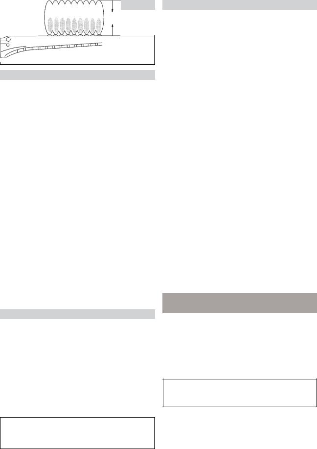
With the heater on, remove the door and make a visual check of the pilot and burner. The flame should be blue with a well-defined pattern.
MAX
Fig. # 8205.2
Fig. # 8964.1
PILOT BURNER FLAME
A yellow or "floating" flame indicates restricted air openings or incorrect orifice size. Should this occur, shut the heater off and contact your installer or gas supplier.
WATER PRESSURE SWITCH
A water pressure switch is provided in the heater to shut off the burners in the event that water supply to the heater is interrupted. It is very important to verify that the switch electrically opens and shuts off the gas valve when water flow to the heater is interrupted. Otherwise, rapid and severe damage will likely occur to the heater. (The water pressure switch should be checked and adjusted for proper operation by a qualified service person at the time of installation and periodically checked thereafter. Refer to Pressure Switch Adjustment on pg. 34 of this manual).
WARNING: Operation of the heater without water circulation will cause rapid and severe damage to the heater.
SECTION 2 - CAUTION
Elevated water temperature can be hazardous, and the U. S. Consumer Product Safety Commission recommends the following guidelines:
1.Spa or hot tub water temperatures should never exceed104°F(40°C). Atemperatureof100°F(38°C) is considered safe for a healthy adult. Special caution is suggested for young children.
2.Drinking of alcoholic beverages before or during spa or hot tub use can cause drowsiness which could lead to unconsciousness and subsequently result in drowning.
3.Pregnant Women Beware! Soaking in water over 102°F (39°C) can cause fetal damage during the first three months of pregnancy resulting in the birth of a brain-damaged or deformed child. Pregnant women should stick to the 100°F (38°C) maximum rule.
4.Before entering the spa or hot tub, users should check the water temperature with an accurate thermometer; spa or hot tub thermostats may err in regulating water temperatures by as much as 4°F (2.2°C).
5.Persons with a medical history of heart disease, circulatory problems, diabetes, or blood pressure problems should obtain a physician's advice before using pools or hot tubs.
6.Persons taking medications which induce drowsiness, such as tranquilizers, antihistamines, or anticoagulant, should not use spas or hot tubs.
SECTION 3 - MAINTENANCE AND CARE PROCEDURES
To be followed one month after start-up and then semiannually.
1.Inspect top of heater and drafthood for soot, a sticky black substance around finned tubes and "V" baffles),andopenfluegaspassageways.Anyvisible soot should be cleaned for proper operation.
CAUTION: Soot may be combustible. Wet sooted surfaces completely prior to cleaning. Do not use steel wire brush.
2.Clean main burners and pilot burner of dust and lint.
3.Inspect and operate all controls, gas valve and pressurereliefvalve.
7
4.Make visual check of the burner and pilot flame. Flame pattern on the main burner and pilot is indicated in the previous illustration. Yellow flame means restriction of the air openings. Lifting or blowing flame indicates high gas pressure. Low flame means low gas pressure. Should the latter occur, shut the heater off and contact your gas
supplier or qualified service agency.
5.On indoor heaters, clean room intake openings to assure adequate flow of combustion and ventilation air.
CAUTION: Combustion air must not be contaminated by corrosive chemical fumes which can damage the heater and void the warranty.
6.Keepareaaroundheaterclearandfreefromcombustible materials, gasoline and other flammable and corrosive vapors and liquids.
BASIC TIPS IF HEATER WILL NOT FIRE:
If you have no electrical power; it may be your "circuit breaker" has tripped. Try re-setting it.
If you have electrical power but the heater will not fire check the following:
1.The time clock must be moved to the "ON" position.
2.Your pump strainer basket may be full. If so remove debris.
3.Your filter may be dirty. If so, backwash or clean filter. (To tell if your filter is dirty, look to see if the filter pressure will be higher than usual).
4.The pump may have lost it's prime. It may be running dry, check the pressure on the filter. If there is no pressure; then you are not moving water (or your gauge is broken). Try to get the pump to run at it's normal flow rate.
POOL & SPA WATER CHEMISTRY
Chemical imbalance can cause severe damage to your heater and associated equipment. Maintain your water pH between 7.4 and 7.8 and total alkalinity between 100 and150p.p.m. Ifthemineralcontentanddissolvedsolids in the water become too high, scale forms inside the heat exchanger tubes, reducing heater efficiency and also damaging the heater. If the pH drops below 7.2, the heater will be severely damaged. This will result in corrosion of the heat exchanger. Heat exchanger damage resulting from chemical imbalance is not covered by the warranty.
AUTOMATIC CHLORINATORS AND
CHEMICALFEEDERS
All chemicals must be introduced and completely diluted into the pool or spa water before being circulated through the heater. Do not place chlorine tablets or bromine sticks in the skimmer. High chemical concentrations will result when the pump is not running (e.g. overnight).
Chlorinators must feed downstream of the heater and have an anti-siphoning device to prevent chemical backup into the heater when the pump is shut off.
NOTE: High chemical concentrates from feeders and chlorinators that are out of adjustment will cause very rapid corrosion to the heat exchanger. Such damage is not covered under the warranty.
COLD WEATHEROPERATION
IMPORTANT FREEZE INFORMATION
MODERATE CLIMATE: Heater operation can continue during short term cold spells. When temperaturesarebelowfreezing,flow(continuouspumpoperation) must be maintained.
CAUTION: Do not use the heater to maintain water temperatures just above freezing or for freeze protection. When heater is used during freezing weather, care must be taken to avoid freeze ups. Continuous pump operation is a must. Additional protection may berequired. Theheaterisnotwarrantedagainstfreeze ups.
COLDCLIMATE:Prolongedoperationwithwatertemperatures below 50°F is not recommended. When starting the heater with pool temperatures below 50°F operate the heater continuously until higher temperatures are reached. Operating the heater for prolonged periods with pool water below 50°F can seriously damagetheheater,andisnotcoveredbythewarranty.
For cold climate areas, please follow the winterizing procedures listed.
8
WINTERIZING THE POOL & SPA HEATER
Heaters installed outdoors in freezing climate areas are subject to be shut down for the winter. Observe the following procedure for winterizing the heater:
1.Turn off gas valve, manual gas valve, and electrical supply to the heater.
2.Open drain plug located on the inlet/outlet header, (under water pipes). Remove the heat exchanger inspection panel on the side opposite water piping to gain access to the drain plug on the return header. Open drain plug on return header.
Return Header
Drain Plug
3.For ASME Heaters only: Disconnect compression fittings from the pressure switch and return header that connects to the 1/4" copper tube and allow the tube to drain. For ASME Heaters only.
9

PART TWO
INSTALLATION AND SERVICE INSTRUCTIONS
SECTION 1 - RECEIVING EQUIPMENT
On receipt of your equipment it is suggested that you visually check for external damage to the carton. If the carton is damaged, a note should be made on the Bill of Lading when signing for equipment. Remove the heater from the carton and if it is damaged, report the damage to the carrier immediately. Save the carton.
These items are shipped loose inside the carton with the heater:
|
STANDARDUNIT(POLYMERHEADERS) |
|
ASME UNIT (CAST IRON HEADERS) |
1. |
"Pagoda" Top |
1. |
"Pagoda" Top |
2. |
2" CPVC Union with "O" rings (2) |
2. |
In/Out Flanges (2) |
3. |
Plastic pipe finish flange for gas line |
3. |
1-1/2" Flange Gaskets (2) |
4. |
Bonding lug with mounting screw |
4. |
2" Flange Gaskets (2) |
|
(IID units only) |
5. |
Flange Bolts (4) |
|
|
6. |
Pressure Relief Valve |
|
|
7. |
2" CPVC Adapters (2) |
|
|
8. |
Plastic pipe finish flange for gas line. |
|
|
9. |
Bonding lug with mounting screw. (IID units only). |
Be sure that you receive the number of packages indicated on the Bill of Lading.
Whenorderingparts,youmustspecifymodelandserialnumberofheater. Whenorderingunderwarrantyconditions, you must also specify date of installation. (Raypak recommends that this manual be reviewed thoroughly before installing your Raypak pool/spa heater. If there are any questions that this manual does not answer, please contact the factory or your local Raypak representative.)
SECTION 2 - GENERAL SPECIFICATIONS
These heaters are design certified and tested under the requirements of ANSI Z21.56 / CSA 4.7 American National Standard / CSA Standard for Gas-Fired Pool Heaters. All heaters can be used either indoor or outdoors. The appropriate top designated for that type of use is required. If desired, the top can be changed at a later date to change from outdoor to indoor or vice versa. Millivolt heater contains a self-generating electrical system operating between
.25 and .75 volts.
Ambient Temperature Rating of Heater Components
Millivolt Heater with Honeywell Gas Valve |
+32°F to +175°F |
Millivolt Heater with Robertshaw Gas Valve |
0°F to +175°F |
Electronic Ignition Heaters* -32°F to + 175°F
*Requires 120V or 240V Power Supply
Atmospheric heaters:
Rated inputs suitable for up to 2000 feet elevation. For elevations above 2000 feet, reduce input 4% for each 1000 feet above sea level, as high elevation reduces combustion performance.
Low NOx heaters:
Rated inputs suitable for up to 5000 feet elevation. For elevations above 5000 feet, consult the factory.
10
SECTION 3 - INSTALLATION INSTRUCTIONS
CALIFORNIA PROPOSITION 65 WARNING: This product contains chemicals known to the State of California to cause cancer, birth defects or other reproductive harm.
IMPORTANTNOTICE
These instructions are intended for the use of qualified personnel only, specifically trained and experienced in the installation of this type of heating equipment and related system components. Installation and service personnel may be required by some states to be licensed. If your state is such, be sure your contractor bearstheappropriatelicense. Personsnotqualifiedshall not attempt to fix this equipment nor attempt repairs according to these instructions.
WARNING:
Improper installation, adjustment, alteration, service or maintenance may damage the equipment, create a hazard resulting in asphyxiation, explosion or fire, and will void the warranty.
CODEREQUIREMENTS
NOTE: The heater should not be located in an area where possible water leakage will result in damage to the area adjacent to the appliance or to the structure. When such locations cannot be avoided, it is recommended that a suitable drain pan, adequately drained, be installed under the appliance. The pan must not restrict combustion air flow.
Installation must be in accordance with local codes, or, in the absence of local codes, with the latest edition of the National Fuel Gas Code, ANSI Z223.1 and National Electrical Code, ANSI/NFPA 70, and for Canada, the latest edition of CAN/CGA-B149.1 and B149.2, and Canadian Electrical Code, CSA C22.1 Part 1 and Part 2.
BASEINSTALLATION
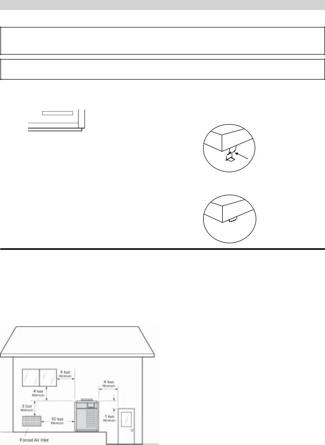
Heater must be mounted on a level base, such as cement slab, cement blocks or other non-combustible surface. An optional non-combustible base is available for all models.
Analternativemethodforprovidingabaseforcombustible floors is illustrated below. Heaters must not be installed on carpeting.
12" Minimum
4"  Minimum
12" Minimum
HEATER
Fig. # 8148.1
Sheet Metal
24 Gauge
Utilize hollow concrete cinder blocks, align holes and leave ends open.
CLEARANCES
ALL HEATERS
For clearances from combustible surfaces, see the chart below.
CLEARANCEFROM
COMBUSTIBLECONSTRUCTION
INDOORINSTALLATIONS:
Top*- 30"(Drafthood) |
Back - 6" |
Front - Alcove |
Right Side - 12" (Water Side) |
Vent - 6" |
Left Side - 6" |
|
(Opposite Water side) |
OUTDOORINSTALLATION:
Top* - Unobstructed (Stackless top or outdoor stack)
Back - 6"
Side - 6"
*Clearance from top of vent terminal
When installed according to the listed minimum clearances from combustible construction materials, the Raypak pool heaters can still be serviced without removing permanent structural construction around the heater.
However for ease of servicing, we recommend a clearance of at least 24" in the front, and at least 18" on the water connection side. This will enable the heater to be serviced in its installed location, that is, without movement or removal of the heater.
Clearances less than these (6" minimum), may require removaloftheheatertoserviceeithertheheatexchanger or the burner tray. In either case, the heater must be installed in a manner that will enable the heater to be serviced without removing any structure around the heater.
11
OUTDOORHEATERINSTALLATION
These heaters are design certified for outdoor installation, when equipped with the approved tops designated for outdoor use.
WARNING: The heater shall not be located in an area where water sprinklers, or other devices, may cause water tospraythroughthecabinetlouversandintotheheater. Thiscouldcauseinternalrustingordamagesomeelectrical components, and this would void the warranty.
WARNING: Do not install within 3 feet of a heat pump or an outdoor condensing unit. Strong air intake from these equipment can disturb the combustion process and cause damage or personal injury.
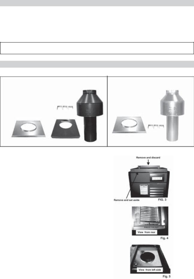
HEATER WITH OUTDOOR STACKLESS TOP |
VENT TERMINAL (Outdoor) Stackless Top Installation |
|
1. Insert tabs into keyhole (4 places). |
Pagoda Top (Shipped Loose with Heater)
2. Snap tabs into keyholes so as not to pull out.
Fig. # 8278.2 |
Fig. #RP8280.1 |
|
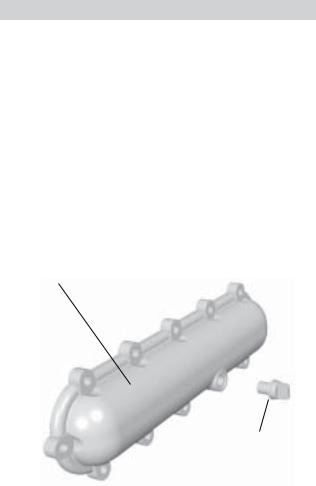
Heaters must not be installed under an overhang of less than three (3) feet from the top of the heater. Three (3) sides must be open in the area under the overhang. Roof water drainage must be diverted away from the heaters installed under overhangs with the use of gutters.
ForU.S.installations,the point from where the flue products exit the heater must be a minimum of four (4) feet below, four (4) feet horizontally from, or one (1) foot above any door, window or gravity inlet into any building. The top surface of the heater shall be at least three (3) feet above any forced air inlet, or intake ducts located within ten (10) feet horizontally.
|
|
For installations in Canada, pool heaters shall not be |
|
|
installed with the top of the vent assembly within 10 feet |
|
|
below, or to either side, of any opening into the building. |
|
|
Refer to the latest revisions of CAN/CGA-B149.1 and |
U.S. Installations only |
Fig# 8245.1 |
B149.2. |
|
|
12
INDOORHEATERINSTALLATION
The design is also certified for indoor installation when equipped with the approved draft hood.
For Canada, indoor installation is restricted to an enclosure that is not occupied and does not directly communicate with occupied area. Refer to the latest edition of CAN/CGA-B149.1 and B149.2 for specific requirements.
Locate heater as close as practical to a chimney or gas vent. Heater must always be vented to the outside. See Vent Piping section (pg. 17) for venting details. Minimum allowable space is shown on the nameplate.
WARNING: Indoor boilers require a drafthood that must be connected to a vent pipe and properly vented to the outside. Failure to follow this procedure can cause fire or fatal carbon monoxide poisoning.
OUTDOOR STACK / INDOOR STACK INSTALLATION
NOTE: The outdoor and indoor stack are optional equipment and do not come standard with the heater.
OUTDOORKITINCLUDES: |
|
INDOORKITINCLUDES: |
|||
1- Draft hood, painted |
|
1- Draft hood, unpainted |
|||
1- Adapter plate |
|
1- Adapter plate |
|||
3- Mounting brackets (clips) |
|
3- Mounting brackets (clips) |
|||
1- Top panel cover |
|
3- Screws |
|||
2- 1 foot sections of metal tape |
|
1- Instructions |
|||
3- Screws |
|
Clips |
|||
1- Instructions |
|||||
|
|
||||
|
|
|
|
Clips |
|
|
|
|
|
||
|
|
OUTDOORSTACK |
INDOORSTACK |
|
|
Model |
|
Part No. |
Part No. |
|
|
185 |
|
006751 |
006696 |
|
|
265 |
|
006752 |
006697 |
|
|
335 |
|
006753 |
006698 |
|
|
405 |
|
006754 |
006699 |
|
|
ASSEMBLY PROCEDURE
1.Make sure that the gas and electricity to the unit has been turned off.
2.Remove the "pagoda" top from the louvered top and discard. See Fig. 3.
3.Remove the louvered top and set aside, saving the four phillips screws for reassembly. See Fig. 3.
4.Remove and discard the rain shield. See Fig. 4.
5Install adapter plate on top of heater flue collector. See Fig. 5.
6.Reinstall louvered top on heater and fasten with Phillips screws set aside in step 3.
13
SECURING THE TOP PANEL COVER
INDOOR KIT ONLY
7.Reinstall the louvered top.
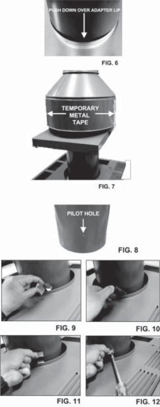
8.Mount the draft hood onto the adapter plate lip inside the heater. See Fig. 6.
9.Proceed to installing the clips, step 14.
SECURING THE TOP PANEL COVER
OUTDOORKITONLY
10.After removing the drafthood from the box, slide the top panel cover over the draft hood.
11.Holding both pieces together, mount the draft hood on the adapter plate lip inside the heater. See Fig. 6.
12.Take the two pieces of tape and attach to each side of the drafthood leaving 6" hanging down.
13.Slidethetoppanelcoverupandattachthetapetothe underneath side. This is to temporarily keep the top panelcoveroutofthewaywhileyouareattachingthe clips as shown in the next steps. See Fig. 7.
INSTALLING THE CLIPS
INDOOR & OUTDOOR KITS
14.Notice that there are three pilot holes above the base of the drafthood as shown in Fig.8. These are the locations where the three clips are to be attached.
15.Insert the longedge of oneclipbetween thetoppanel cover and the drafthood, see Fig. 9.
16.With a twisting motion, rotate the clip up, see Fig. 10.
17.Pull up on clip, see Fig. 11.
18.Hold the clip up and align the clip hole to the pilot hole, see Fig. 12.
19.Insert screw into hole and secure using a 5/16" nut driver.
20.Repeat steps 15-19 using remaining two clips.
21.This completes the indoor drafthood installation. If installing an outdoor drafthood, proceed to step 22.
14
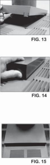
INSTALLING THE TOP COVER
OUTDOORKITONLY
22.Remove the two pieces of metal tape holding the top panel cover up and discard.
23.Insert the reartwo tabsinto the slots onthe heater top andslidethetoppanelcoverbackwards.SeeFig.13.
24.Lower the top panel cover and using your thumbs, push tabs in and insert the two front tabs into the slots on the top of the heater. See Fig.14.
25.Lowerthetoppanelcoverflushtothetopandrelease the tabs. They will spring into place as shown in Fig.15.
26.Turn the gas and electricity to the heater on.
15

SPECIFICATIONS AND DIMENSIONS
|
|
|
|
|
|
|
|
Shipping Weights (lbs) |
|
||
|
|
|
|
|
|
|
|
|
|
|
|
|
BTUH |
(A) |
(B) |
(C) |
(J) |
|
|
Cast Iron |
Capron |
|
|
|
|
|
Heater |
Heater |
|
Indoor |
|||||
Heater |
Input |
Cabinet |
Flue |
Indoor |
|
Gas |
Water |
|
|||
|
w/Stackless |
w/Stackless |
|
Draft- |
|||||||
Model |
(000) |
Width |
Dia. |
Drafthood |
|
Conn. |
Conn. |
Top |
Top |
|
hood |
R185B |
181 |
18-1/4" |
6" |
62-5/8" |
12-1/16" |
3/4" |
2" |
191 |
172 |
|
12 |
R265B |
264 |
22-3/8" |
7" |
62-7/8" |
11-1/8" |
3/4" |
2" |
214 |
195 |
|
15 |
R335B |
334 |
25-3/4" |
8" |
63-3/4" |
10-3/4" |
3/4" |
2" |
234 |
215 |
|
17 |
R405B |
399 |
29-1/4" |
9" |
65-3/8" |
12-1/2" |
3/4" |
2" |
253 |
234 |
|
20 |
*Designation for Propane is "EP", Natural gas is "EN". Prefix "C" is for Cast Iron (ASME) Headers; "P" is for Plastic (Polymer) Headers. Atmospheric heaters: reduce input 4% for each 1000 ft. above sea level when installed above 2000 ft. elevation. Low NOx heaters: for elevations above 5,000 feet consult factory. For Canada, no de-rating is required for elevations up to 4500 feet. Manufactured under Patent No. 3,623,458. Note: Plastic (Polymer) headers cannot be used for ASME installations.
Fig # 9037.2
*Electrical Connection On Left Side is 19-1/8".
COMBUSTION AND VENTILATION AIR (Indoor Units Only)
Theheatermusthavebothcombustionandventilationair. Minimum requirements for net free air supply openings, one opening that is 12 inches from the ceiling for ventilationandoneopeningthatis12inchesfromthefloor for combustion air as outlined in the latest edition of the National Fuel Gas Code, ANSI Z2231(Canada-CAN/ CGA-B149.1 and B149.2) and any local codes that may have jurisdiction.
CAUTION: Combustion air must not be contaminated by corrosive chemical fumes which can damage the heater and void the warranty.
a. All Air From Inside The Building:
Each opening shall have a minimum net free square |
|||
inches as noted: |
|
|
|
Model Square Inches Model Square Inches |
|||
185 |
181 |
335 |
333 |
265 |
264 |
405 |
399 |
b. All Air From Outdoors:
When air is supplied directly from outside of building, each opening shall have a minimum net free square inches as noted:
Model
185
265
335
405
16
 Loading...