

Raymarine ST60 User Manual

ST60 Compass
Instrument
Owner’s
Handbook
Document number: 81107-4
Date: 1 April 2004

Raymarine, ST60 and SeaTalk are trademarks of Raymarine Limited
© Handbook cont ents c opyright Raymarine Limited 2004

Preface i
Preface
Important information
Safety notices
WARNING: Product installation & operation
This equipment must be installed and operated in accordance
with the Raymarine instructions provided. Failure to do so could
result in personal injury, damage to your boat and/or poor product
performance.
WARNING: Electrical safety
Make sure you have switched off the power supply before you
start installing this product.
WARNING:
Although we have designed this product to be accurate and
reliable, many factors can affect its performance. Therefore, it
should serve only as an aid to navigation and should never replace
commonsense and navigational judgement. Always maintain a
permanent watch so you can respond to situations as they
develop.
EMC conformance
All Raymarine equipment and accessories are designed to the best industry
standards for use in the recreational marine environment.
The design and manufacture of Raymarine equipment and accessori es conform to
the appropriate Electromagnetic Compatibility (EMC) standards, but correct
installation is required to ensure that performance is not compromised.
Handbook information
To the best of our knowledge, the information in this handbook was correct when
it went to press. However, Raymarine cannot accept liability for any inaccuracies
or omissions it may contain.
In addition, our policy of continuous product improvement may change
specifications without n otice. Therefore, Raymarine cannot ac cept liability for any
differences between the product and the handbook.

ii ST60 Compass Instrument Owner’s Handbook

Preface iii
Contents
Preface ......................................................................................................................i
Important information ..................................................................................... i
Safety notices .......................................................................................... i
EMC conformance ................................................................................... i
Handbook information ............................................................................ i
Contents................................................................................................... iii
Introduction ...................................................................................................vii
Data inputs ....................................................................................................vii
SeaTalk .................................................................................................viii
Stand alone operation ..........................................................................viii
Remote control .............................................................................................viii
Mounting options .........................................................................................viii
Parts supplied ................................................................................................ ix
Chapter 1: Operation ............................................................................................1
1.1 Getting started ....................................................................................... 1
Displayed information ............................................................................ 1
Digital display .................................................................................. 1
Pointer ............................................................................................. 2
Use with Sea Talk autopilot .................................................................... 2
1.2 Normal operation ................................................................................... 2
Unlocked mode ...................................................................................... 3
Course over ground (COG) ............................................................... 3
Average heading .............................................................................. 3
Locked mode .......................................................................................... 4
Operation ......................................................................................... 5
Auto mode ............................................................................................. 6
1.3 Display illumination ............................................................................... 6
1.4 Remote control ...................................................................................... 7
1.5 Operating hints ...................................................................................... 7
Steering sense ........................................................................................ 7
Man overboard/reciprocal course .......................................................... 7
Chapter 2: Maintenance & Troubleshooting .....................................................9
2.1 Maintenance .......................................................................................... 9
Servicing and safety ............................................................................... 9
Instrument ............................................................................................. 9
Cabling ................................................................................................... 9
2.2 Troubleshooting ................................................................................... 10
Preliminary procedures ........................................................................ 10
Fault location ....................................................................................... 10

iv ST60 Compass Instrument Owner’s Handbook
Technical support ..................................................................................11
World wide web .............................................................................11
Telephone help line ........................................................................11
Help us to help you ......................................................................... 11
Chapter 3: Installation .......................................................................................13
3.1 Planning your installation .....................................................................13
Site requirements ................................................................................. 13
Transducer ......................................................................................13
Instrument ......................................................................................14
EMC installation guidelines ..................................................................15
Suppression ferrites ........................................................................ 16
Connections to other equipment ....................................................16
3.2 Procedures ...........................................................................................17
Unpacking ............................................................................................17
Fitting the instrument ...........................................................................17
Surface mounting ...........................................................................17
Flush mounting .............................................................................. 18
Fitting the low-profile bezel ......................................................18
Flush mounting procedure .......................................................20
Bracket mounting ...........................................................................21
Fitting transducer .................................................................................21
Installation .....................................................................................21
Running transducer cable ...............................................................22
General ....................................................................................22
Connecting the instrument ................................................................... 23
Introduction ...................................................................................23
Signal connections .........................................................................23
Power supply connections ..............................................................24
SeaTalk systems ....................................................................... 24
Stand alone instruments ..........................................................24
Chapter 4: Calibration ........................................................................................ 27
4.1 Introduction ..........................................................................................27
EMC conformance ................................................................................27
4.2 User calibration ....................................................................................27
Linearization ......................................................................................... 28
Heading alignment ...............................................................................28
Lock mode ............................................................................................ 28
Variation setting ...................................................................................29
True/magnetic selection ........................................................................30
Leaving User calibration .......................................................................30
4.3 Intermediate calibration .......................................................................30
Software version number .....................................................................30

Preface v
Master/repeater status ......................................................................... 30
Leaving Intermediate calibration ......................................................... 31
4.4 Dealer calibration ................................................................................. 31
Calibration on/off ................................................................................. 32
Pointer response .................................................................................. 32
Heading display response .................................................................... 32
Boat show mode .................................................................................. 32
Factory defaults .................................................................................... 32
Leaving Dealer calibration .................................................................... 33

vi ST60 Compass Instrument Owner’s Handbook

Preface vii
Introduction
Thank you for purchasing a Raymarine prod uct. We are sure your ST60 instrument
will give you many years of trouble-free operation.
This handbook describes how to install and use the Raymarine ST60 Compass
instrument. This instrument gives:
• True/Magnetic Course Heading.
• Current or Locked Heading.
• Course Over Ground (COG).
• Average Heading.
The ST60 Compass instrument is constructed in a rugged weather proofed case. It
provides a sensitive and stable, combined analog and digital display, to deliver
accurate information under even the most demanding conditions.
The ST60 Compass instrument provides Compass Heading, shown in digital form
(numerals) plus (when in Locked mode) Steering Course Error to ±30
of locked course heading, shown in analog form (pointer). The Compass
instrument can be used either as a stand-alone unit, or as part of an integrated
SeaTalk instrumentation system.
Data inputs
The ST60 Compass instrument receives data either from an associated Flux Gate
Compass transducer and/or from a SeaTalk instrumentation system.
D4320-3
° deviation

viii ST60 Compass Instrument Owner’s Handbook
SeaTalk
SeaTalk enables a number of compatible instruments to be interconnected and
operate as a single, integrated navigational system.
Power and data in a SeaTalk system are fed via a single cable, so that instruments
can be connected by plugging them into the network. SeaTalk is flexible enough
to adapt to any number of compatible instruments without requiring a central
processor. SeaTalk can also communicate with non-SeaTalk equipment, using the
internationally-accepted National Marine Electronics Association (NMEA)
protocol.
In a SeaTalk system, each instrument can be either a master or dedicated repeater
unit. A master instrument is directly connected to a transducer (the device that
provides the raw data) and has control of all other equipment on the SeaTalk
network. A slave instrument is not directly connected to a transducer but repeats
information provided by other equipment in the SeaTalk network.
Stand alone operation
In Stand alone operation, the ST60 Compass instrument is connected only to the
relevant transducer and does not display information from, or provide
information to, any other instruments.
Remote control
When connected to SeaTalk, the ST60 Compass instrument can be controlled
remotely by a SeaTalk Remote Keypad Unit, to provide instant remote access to
the various display readouts from the ST60 range of equipment.
Mounting options
If you do not want to surface mount your ST60 instrument, options are available
for:
• Flush mounting. If you have ordered the flush mounting option a low-profile
bezel and four fixing screws are also provided.
• Bracket mounting.

Preface ix
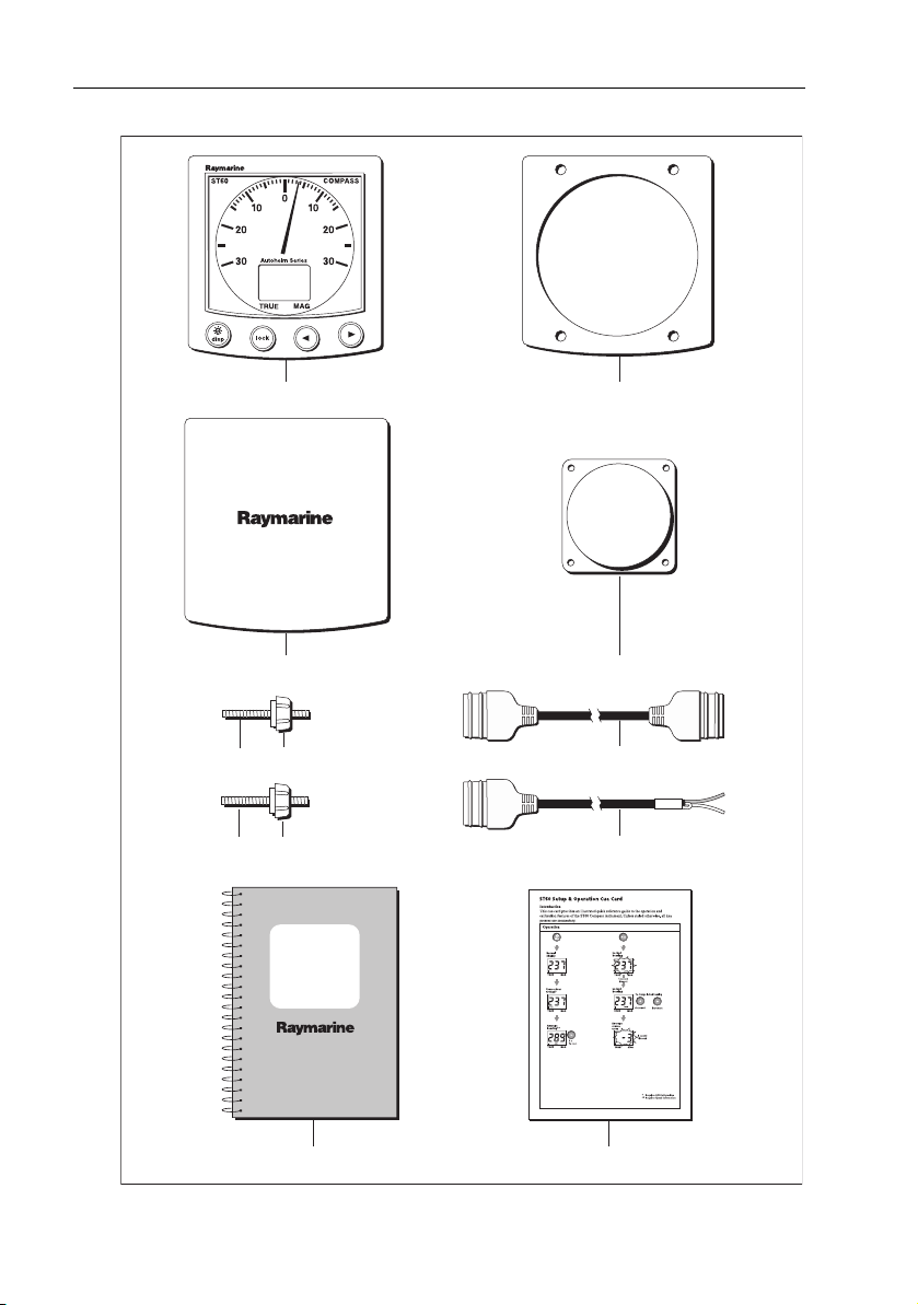
Parts supplied
Unpack your ST60 instrument and check that the following items are present:
• Item 1, ST60 Compass instrument with standard bezel.
• Item 2, Fixing studs (2).
• Item 3, Thumb nuts (2).
• Item 4, Gasket.
• Item 5, Fluxgate Compass transducer.
• Item 6, SeaTalk interconnection cable.
• Item 7, Power cable.
• Item 8, Instrument Cover.
• Item 9, Owner’s Handbook. The Warranty document and mounting temp lates
are included in this Handbook.
• Item 10, Cue Card.
Spare spade terminals are also provided, to re-terminate the transducer cable if it
has to be cut to facilitate installation.
Note:
Note: The above packing list is for an ST60 Compass system. Where an instrument
is purchased separately, the Fluxgate Compass transducer is not included.
x ST60 Compass Instrument Owner’s Handbook
1 4
8
32
32
ST60 Steering
Compass
Instrument
Owner's
Handbook
109
5
6
7
COMPASS
D4444-3

Chapter 1: Operation 1
Chapter 1: Operation
1.1 Getting started
This handbook describes how to operate, maintain and install the Raymarine
ST60 Compass instrument. The Compass instrument shows both compass
heading and steering indication. Where GPS or similar positioning data is
available from another instrument, Course Over Ground (COG) can be calculated
and used to provide a true course display.
CAUTION: Calibration requirement
The ST60 Compass instrument is calibrated to factory (default)
settings when first supplied. To ensure optimum performance on
your boat, this product must be calibrated before use. Do NOT use
the product until it has been calibrated using the procedures in
Chapter 4, Calibration
If the CAL legend on the digital display flashes for the first 30 seconds after any
power up, use the appropriate procedures in
1. Apply the factory defaults.
2. Carry out the linearization procedure.
.
Chapter 4, Calibration
to:
Displayed information
The information displayed on the ST60 Compass instrument is presented by
means of a pointer and a digital display. The pointer gives a steering indication
and the digital display shows the compass heading.
Note:
The TRUE and MAG indicators flash for 8 seconds after power is switched on. This
is a function of the remote control system and can be ignored if remote control is not being
used.
Digital display
The digital display shows various course information:
• True/Magnetic Course Heading, or
• Locked Heading, or
• Course Over Ground (COG), or
• Average Heading.

2 ST60 Compass Instrument Owner’s Handbook
Pointer
In locked mode, the analog pointer shows any course error between the current
heading and the locked course, up to a maximum ±30º deviation. In unlocked
mode, the pointer always indicates zero.
Note:
When power is first switched on, the ST60 Compass starts in unlocked mode.
Use with Sea Talk autopilot
If the ST60 Compass instrument forms part of a system which includes a Sea Talk
autopilot operating in Auto, Vane or Track mode, the ST60 Compass instrument is
forced to operate in Auto mode.
In Auto mode the ST60 Compass instrument acts as a slave display to the
autopilot, with the autopilot’s locked heading displayed on the ST60 Compass
instrument digital display and the analog pointer showing the autopilot course
error. In this mode, all ST60 Compass instrument key functions, except
illumination, are disabled.
1.2 Normal operation
Use the
Basic operation
operate your ST60 Compass instrument. The flow charts show the sequence of
key presses and displays for the various operating tasks. All key presses called for
in the flow charts are momentary, unless otherwise stated.
The displayed heading is either TRUE or MAG(netic) as indicated by a black
square marker on the digital display, adjacent to the corresponding legend.
and
Using the disp key
flow charts in this Chapter to
The ST60 Compass instrument has three modes of operation:
• Unlocked - displays live course data.
• Locked - displays course data and live course deviation data.
• Auto - displays autopilot course data and live course deviation data.
Chapter 1: Operation 3
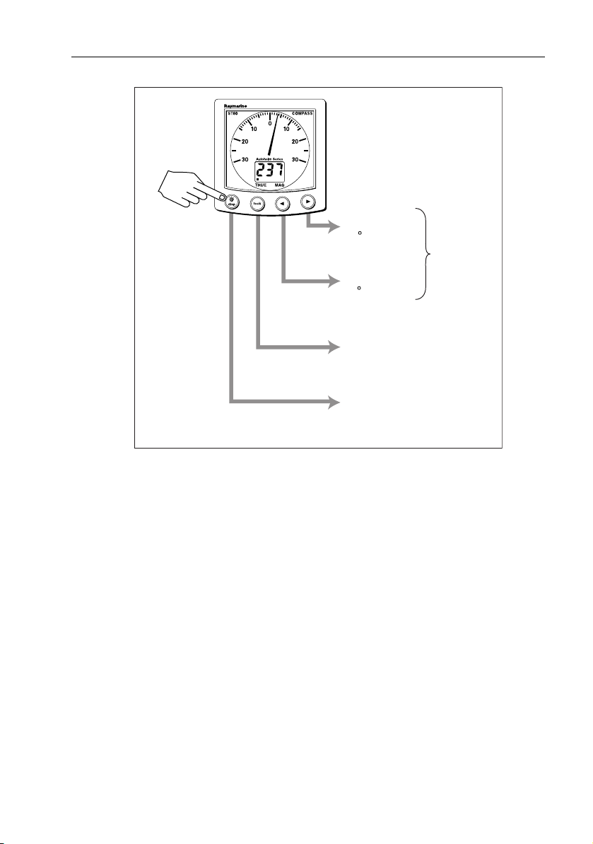
Momentarily press
the required
key
Press to increment
locked mode heading
in 1 degree steps.
Press to decrement
locked mode heading
in 1 degree steps.
Press to toggle between
locked & unlocked modes.
Lock mode operation
(see flow chart)
In unlocked mode, press to access
COG & average heading information.
(see flow chart)
Using the disp key
Keep pressed
for rapid change.
Basic operation
D4387-2
Unlocked mode
The Compass instrument always powers-up in the unlocked mode. The current
heading is displayed on the digital display (true or magnetic) and the analog
pointer indicates zero. Momentarily press the lock key to switch to locked mode.
Course over ground (COG)
Press the disp key to select COG. Provided you have GPS or similar positioning
data on the SeaTalk system, the ST60 Compass instrument displays your course
over the ground. If such data is not available the digital display shows “---”.
Average heading
Press the disp key again from the COG display to temporarily display the current
calculated Average Heading. You can reset the average value by pressing the >
key for 3 seconds when the Average heading screen is displayed.
 Loading...