

Raymarine ST60 User Manual
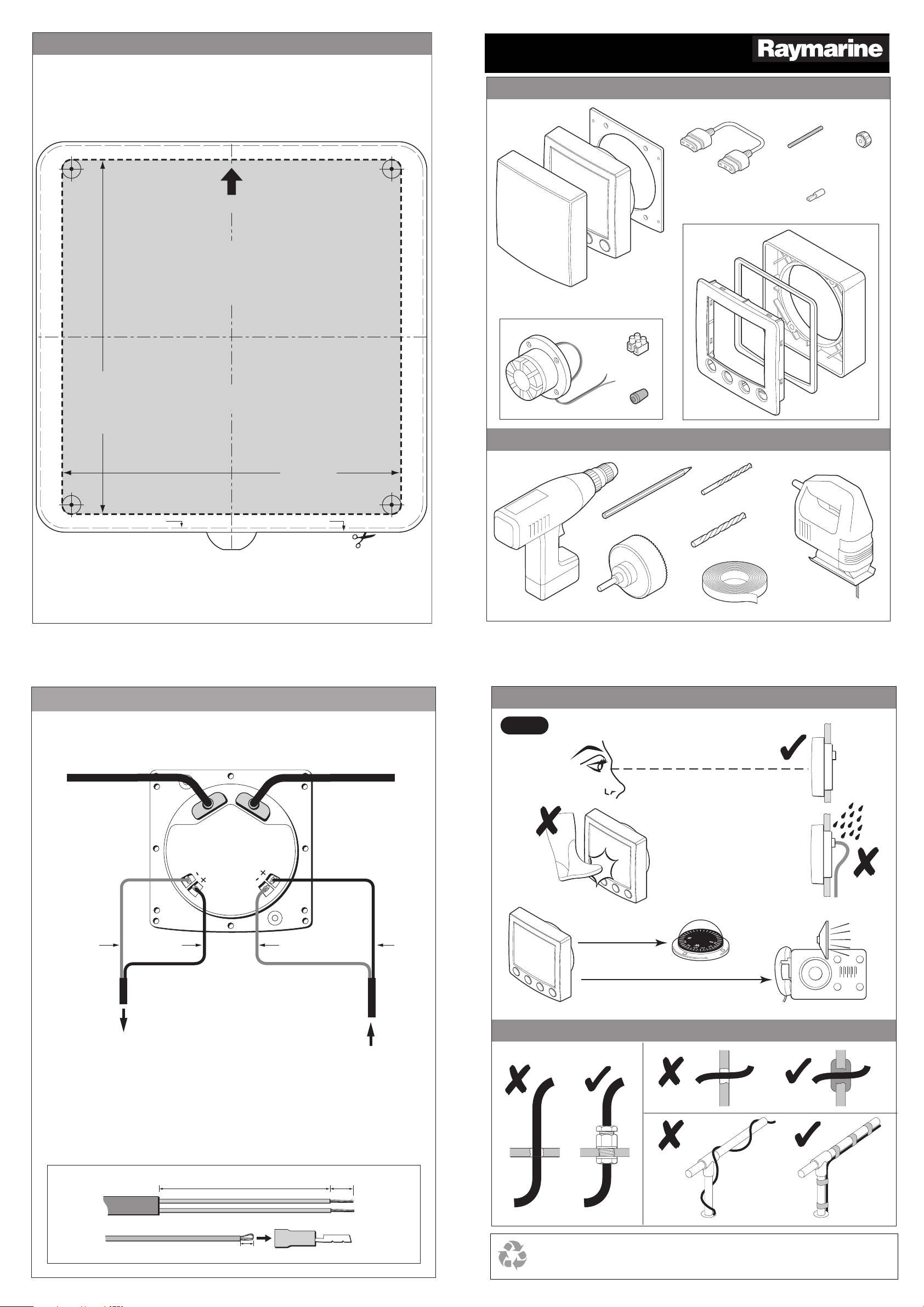
Flush mount template
ST60 Graphic Display
Installation Guide
Parts supplied
®
www.raymarine.com
SeaTalk Cable
114 mm (4.5 in)
UP
ST60 Graphic Display
FLUSH MOUNT
Template
Remove material
from shaded area only
Drill hole,
6 mm (1/4 in)
diameter in
4 positions
Sun cover
Auxiliary Alarm option
Auxiliary Alarm
Tools required
Gasket
ST60 Graphic Display
(ready for
surface mounting)
Connector
block
Grommet
Flush mount option
Stud (x2)
Connector (x2)
Gasket
Bezel
Thumb nut (x2)
Bracket
Instrument edge
Connection details
SeaTalk cable
109 mm (4.3 in)
Sun cover edge
SeaTalk cable
D6465-1
Power Drill
Site requirements
Check
Pencil
3½ in (90 mm) Hole Cutter
3
/16 in (5 mm) Drill
1
/4 in (6 mm) Drill
Adhesive tape
Jig saw
(only required if
flush mounting
the Display)
D6463-1
N
M
E
A
O
U
T
Either:
Data out to NMEA system
or
External alarm signals to Auxiliary Alarm
Use the procedures in the ST60 Graphic
Display Commissioning Guide to set the
function for the NMEA OUT connector.
50 mm
N
I
A
E
M
N
Blue RedBlue Red
Min 9 in (230 mm)
Min 20 in (500 mm)
Running cables
Data in from NMEA
system
6 mm
3 mm
D6466-1
Raymarine Ltd, Portsmouth, Hampshire, UK PO3 5TD
Raymarine Inc. Nashua, NH 03063-4219, USA
Recyclable Material - Please dispose of responsibly.
D6464-2
+44 (0) 23 9269 3611
Toll Free: 800-539-5539
+1 603-881-5200
87022-1
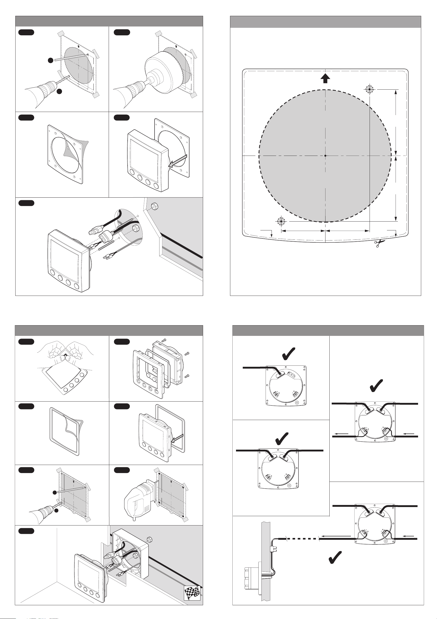
Surface mount display
Surface mount template
Step 1 Step 2
ST60 Graphic Display
SURFACE MOUN
Template
T
U
P
Drill hole, 3/16 in (5 mm)
dia
meter in 2 positions
Cu
3.54 in (90 mm)
t hole
dia
me
fr
om
30.1 mm (1.185
ter
45.0 mm
R
em
ov
sh
a
in)
(1.77 in)
e m
d
a
te
ed
ria
a
re
l
a
s
o
n
ly
44
.6 m
(1
m
.75 in
)
30.0 mm (1.18 in)
Sun cover
edg
e
x2
Instrument
edge
x2
Step 4Step 3
ST60 Graphic Disp
SU
RFACE MOUNT
Template
Instrument
ed
ge
lay
fr
om
30.1 mm (1.185
U
P
Drill hole, 3/16 in (5
dia
meter in 2 positio
mm)
ns
Cu
3.54 in
t ho
le
(90
diame
mm)
ter
45.0 mm
R
em
o
sh
ad
in)
(1.77 in)
v
e m
a
te
e
d
ria
a
re
l
a
s o
30.0 mm (1.18 in)
nly
4
4.6 m
(1.75 in
m
)
Sun cove
edge
r
ST60 Graphic Display
SURFACE MOUNT
Template
UP
Cut hole
3.54 in (90 mm)
diameter
Drill hole, 5 mm (3/16 in)
diameter in 2 positions
45.0 mm
(1.77 in)
Remove material
from shaded areas only
44.6 mm
(1.75 in)
Step 5
Flush mount display
Sun cover
edge
D6469-1
D6467-1
Instrument
edge
30.1 mm (1.185 in) 30.0 mm (1.18 in)
Connection options
Step 2Step 1
Step 5
SeaTalk cable
N
M
E
A
O
U
T
N
I
A
E
M
N
SeaTalk cable
SeaTalk cable
Step 4Step 3
N
SeaTalk cable
SeaTalk cable
M
E
A
O
U
T
N
I
A
E
M
N
NMEA inNMEA out
Step 6
N
M
E
A
O
U
T
114 mm (4.5 in)
Instrument edge
U
P
ST60 Graphic Di
FLU
SH
splay
M
Tem
O
UN
plate
Rem
from shaded area only
ove m
aterial
T
Sun cover edge
109 mm (4.3 in)
1/4 in (6 mm)
Drill hole,
diameter in
4 positions
U
P
ST60 Graphic Display
FLUSH
Drill hole,
1/4 in (6 mm)
diameter in
M
Tem
4 positions
O
UN
plate
114 mm (4.5 in)
Instrument edge
Remove m
from shaded area only
aterial
T
Sun cover edge
109 mm (4.3 in)
x2
x2
N
I
A
E
M
N
SeaTalk cableSeaTalk cable
Step 7
D6468-1
Auxiliary
alarm
Connector block
Grommet
External alarm signals
N
M
E
A
O
U
T
N
I
A
E
M
N
NMEA in
D6470-1
 Loading...