


OPERATING, SERVICE
AND MAINTENANCE
MANUAL
MODEL DC-200 SERIES
RAM-LOK®EQUIPPED
INDUSTRIAL LOW-MOUNT WINCHES
INCLUDES: DC-200/DC-246, DC-24-200/DC-24-246.
DCY-200/DCY-246, DCY-24-200/DCY-24-246
AND MODELS EQUIPPED WITH OPTIONAL ADJUSTABLE, AUTOMATIC OIL COOLED SAFETY BRAKE: DCG-200, DCYG-200 SERIES WINCHES
CAUTION: READ AND UNDERSTAND THIS MANUAL BEFORE INSTALLATION AND OPERATION OF WINCH. SEE SAFEGUARDS AND WARNINGS!

TABLE OF CONTENTS
INTRODUCTION................................................................................................ |
1 |
WARRANTY INFORMATION............................................................................ |
1 |
SPECIFICATION............................................................................................... |
1 |
TECHNIQUES OF OPERATION....................................................................... |
2 |
WARNINGS....................................................................................................... |
2 |
WINCH MAINTENANCE................................................................................... |
3 |
WINCH MOUNTING.......................................................................................... |
4 |
ELECTRICAL CONNECTIONS......................................................................... |
4 |
CABLE INSTALLATION.................................................................................... |
4 |
ADJUSTING THE OIL COOLED SAFETY BRAKE........................................... |
4 |
SERVICING OF THE OIL COOLED SAFETY BRAKE...................................... |
5 |
RE-ASSEMBLING AND CHECKING THE BRAKE........................................... |
6 |
TEST FOR PROPER BRAKE ASSEMBLY....................................................... |
6 |
INSTRUCTIONS FOR CHECKING ASSEMBLY |
|
ARRANGEMENT AND SETTING OF WORM BRAKE...................................... |
7 |
TROUBLE SHOOTING GUIDE..................................................................... |
8-9 |
INSTRUCTIONS FOR OVERHAUL OF |
|
RAMSEY MODEL DC-200 SERIES RAM-LOK® WINCHES |
|
DISASSEMBLY............................................................................ |
10-13 |
REASSEMBLY............................................................................. |
13-16 |
DIMENSIONAL DRAWING............................................................................. |
17 |
PARTS LIST AND PARTS DRAWING........................................................ |
18-20 |
SOLENOID AND SWITCH ASSEMBLY PARTS LIST.................................... |
21 |
TEST PROCEDURE FOR SOLENOID.......................................................... |
22 |
TEST PROCEDURE FOR MOTOR............................................................... |
23 |
MOTOR ASSEMBLY PARTS LIST................................................................ |
24 |
LIMITED WARRANTY.................................................................................... |
25 |

RAMSEY ELECTRICAL WINCH MODEL DC-200 SERIES
PLEASE READ THIS MANUAL CAREFULLY.
This manual contains useful ideas in obtaining the most efficient operation from your Ramsey Winch, and safety procedures one needs to know before operating a Ramsey Winch.
WARRANTY INFORMATION
Ramsey Winches are designed and built to exacting specifications. Great care and skill go into every winch we make. If the need should arise, warranty procedure is outlined on the back of your self-ad- dressed postage paid warranty card. Please read and fill out the enclosed warranty card and send it to Ramsey Winch Company. If you have any problems with your winch, please follow instructions for prompt service on all warranty claims. Refer to back page for limited warranty.
*SPECIFICATIONS: Conforms to SAE J706
................................................................................................Rated Line Pull 1st Layer (l bs.) |
|
|
|
|
|
|
|
|
|
|
|
8,000 |
||
|
(kgs.)................................................................................................ |
|
|
|
|
|
|
|
|
|
|
|
3,630 |
|
Total Gear Reduction: DC-200.............................................................................. |
|
|
|
|
|
|
|
|
|
....................... |
|
470 |
||
|
DC-246.................................................................................................... |
|
|
|
|
|
|
|
|
|
|
|
360 |
|
Weight: |
DC-200/DC-246 (long drum) |
.................................................................. |
|
|
|
|
|
|
|
|
116 lb. (52.6 Kgs.) |
|||
|
DCY-200/DCY-246 (short drum).............................................................. |
|
|
|
|
|
|
|
105 lb. (47.6 Kgs.) |
|||||
MAXIMUM GEAR BOX OIL TEMPERATURE SHOULD NOT EXCEED................................................ |
|
|
|
|
|
|
2500F |
|||||||
Layer of Cable |
|
|
1 |
|
2 |
|
3 |
|
|
|
4 |
|||
Rated Line Pull |
|
Lbs. |
8,000 |
6,700 |
5,700 |
|
5,000 |
|||||||
per layer |
|
Kgs. |
3,620 |
3,030 |
2,580 |
|
2,260 |
|||||||
Long Drum Cable |
Ft. |
25 |
|
60 |
|
95 |
|
|
140 |
|||||
capacity per layer |
M. |
7 |
|
18 |
|
28 |
|
|
42 |
|||||
Short " Y" Drum |
|
|
|
|
|
|
|
|
|
|
|
|
|
|
cable capacity |
|
Ft. |
15 |
|
30 |
|
55 |
|
|
75 |
||||
per layer |
|
M. |
4 |
|
9 |
|
16 |
|
|
22 |
||||
|
|
|
NO LOAD |
2000#LOAD |
4000# LOAD |
8000# LOAD |
||||||||
Line Speed |
|
|
FPM |
|
|
FPM |
|
|
FPM |
|
|
FPM |
|
|
|
|
VOLTS |
(MPM) |
AMPS |
(MPM) |
AMPS |
(MPM) |
AMPS |
(MPM) |
AMPS |
||||
DC-200/DCY-200 |
12 |
14 |
|
65 |
7 |
|
110 |
5 |
|
180 |
3.5 |
|
280 |
|
DC-24-200/DCY-24-200 |
24 |
(4.3) |
|
30 |
(2.1) |
|
50 |
(1.5). |
|
90 |
(1.1). |
|
140 |
|
DC-246/DCY-246 |
12 |
16.5 |
|
70 |
8.5 |
|
140 |
5.5 |
|
200 |
3.5 |
|
330 |
|
DC-24-246/DCY-24/246 |
24 |
(5) |
|
35 |
(2.5) |
|
70 |
(1.7). |
|
100 |
(1.1). |
|
160 |
|
*These specifications are based on recommended 3/8 inch dia. extra improved plow steel wire rope or equivalent.
 Winch only conforms to SAE J706. For SAE qualification of mounting angles, if applicable, consult Ramsey Engineering.
NOTE: The rated line pulls shown are for the winch only. Consult the wire rope manufacturer for wire rope ratings.
Winch duty cycles are shown below:
MINUTES
6
5
4
3
2
1
0
180 |
270 |
360 |
AMPS
MINUTES
5
4
3
2
1
0
90 |
120 |
160 |
190 |
|
|
AMPS |
|
12V |
24 V |
1
TECHNIQUES OF OPERATION
The best way to get acquainted with how your winch operates is to make test runs before you actually use it. Plan your test in advance. Remember, you hear your winch, as well as see it operate. Get to recognize the sounds of a light steady pull, a heavy pull, and sounds caused by load jerking or shifting.
Gain confidence in operating your winch and its use will become second nature with you.
The uneven spooling of cable, while pulling a load, is not a problem, unless there is a cable pileup on one end of drum. If this happens, reverse the winch to relieve the load and move your anchor point further to the center of the vehicle. After the job is done you can unspool and rewind for a neat lay of the cable.
When pulling a load where there is even a remote chance of cable failure, place a blanket, jacket or tarpaulin over the cable about six feet behind the hook. This will slow the snap back of a broken cable and could prevent serious injury.
Check oil level of winch every six months. Replace oil annually or more often if winch is used frequently. Use 3/4 pint of all purpose E. P. 140 oil in the worm gear housing and 1/2 pint SAE 20 for spur gear box. If the oil is contaminated with metallic particles, inspect winch for cause of abnormal wear. Periodically check all electrical connections and mounting bolts. Tighten hardware if necessary.
The minimum ampere-hour rating of vehicle battery should be 70, and used with at least a 40 amp alternator. An Auxiliary battery is recommended to supply additional battery power. Inspect the cable frequently. If the cable becomes frayed with broken strands, replace immediately. Cable and hook assembly may be purchased from a Ramsey distributor. The RAM-LOK® semi-automatic clutch allows rapid unspooling of the cable, from cable drum, for hooking onto a load. The clutch is operated by the “T-handle”, located on the end of the winch, as follows:
1.TO DISENGAGE CLUTCH, run the winch in the reverse (reel out) direction until the load is off the cable. Pull outward on the clutch handle, rotate it counter-clockwise 900 and release. The clutch is now locked out and the cable may be pulled off by hand.
2.TO ENGAGE CLUTCH, pull outward on the handle, rotate it clockwise 900 and release. Run the winch in reverse until the clutch handle snaps fully in or until the cable drum starts turning. At this point make sure the clutch handle is all the way in. The plastic plug in top of clutch housing may be removed, for inspection of clutch to assure total engagement. After the clutch is fully engaged, the winch is ready for winching in the cable.
WARNINGS
CLUTCH MUST BE TOTALLY ENGAGED BEFORE STARTING THE WINCHING OPERATION. DO NOT DISENGAGE CLUTCH UNDER LOAD.
DO NOT LEAVE CLUTCH ENGAGED WHEN WINCH IS NOT IN USE. STAY OUT FROM UNDER AND AWAY FROM RAISED LOADS.
STAND CLEAR OF CABLE WHILE PULLING. DO NOT TRY TO GUIDE CABLE. DO NOT EXCEED MAXIMUM LINE PULL RATINGS SHOWN IN TABLE.
DO NOT USE WINCH TO LIFT, SUPPORT, OR OTHERWISE TRANSPORT PERSONNEL.
A MINIMUM OF 5 WRAPS OF CABLE AROUND THE DRUM BARREL IS NECESSARY TO HOLD THE LOAD. CABLE CLAMP IS NOT DESIGNED TO HOLD LOAD.
DISCONNECT THE REMOTE CONTROL SWITCH FROM WINCH WHEN NOT IN USE. A RAMSEY PART NO. 282053 SAFETY ON-OFF SWITCH IN YOUR VEHICLE IS RECOMMENDED.
2

WINCH MAINTENANCE
Adhering to the following maintenance schedule will keep your winch in top condition and performing as it should with a minimum of repair.
A.WEEKLY
1.Check the oil level and maintain it to the oil level plug. If oil is leaking out, determine location and repair.
2.Check the pressure relief plug in top of the gear housing. Be sure that it is in good operating condition so that hot oil gasses may escape.
3.Lubricate cable with light oil.
B.MONTHLY
1.Lubricate the various grease fittings located in the cable drum, end bearing, clutch housing or clutch operating linkage. Any good grade of moly-disulfide containing grease is acceptable.
2.Check the action of the sliding clutch, making sure it is fully engaging and disengaging with the cable drum. Remove the plastic plug in top of the housing and observe if the clutch is fully engaging. If clutch is not fully engaging, inspect clutch shifter assembly parts, check for damage or excessive wear and replace as necessary. Observe the jaws on both the clutch and cable drum, checking for rounding of the driving faces. If rounding has occurred they should be replaced immediately.
3.Check the winch mounting bolts. If any are missing, replace them and securely tighten any that are loose. Make sure to use only grade 5 bolts or better.
4.Check the torque setting of the oil cooled worm brake. Make any adjustments required, following the procedure described in ADJUSTING THE OIL COOLED WORM BRAKE in the Owner’s Manual.
5.Check alignment of chain and sprockets and adjust as required to minimize wear.
6.Inspect the cable. If the cable has become frayed with broken strands, replace immediately.
C.ANNUALLY
1.Drain the oil from the winch annually or more often if winch is used frequently.
2.Fill the winch to the oil level plug with clean kerosene. Run the winch a few minutes with no load in the reel in direction. Drain the kerosene from the winch.
3.Refill the winch to the oil level plug with all purpose EP 140 gear oil.
4.Inspect frame and surrounding structure for cracks or deformation.
5.Gear wear can be estimated by rocking the drum back and forth and if necessary drain oil and remove cover for closer inspection.
3

WINCH MOUNTING
WINCH MOUNTING
It is most important that this Winch be mounted securely so that the three major sections (the clutch housing end, the cable drum and the gear housing end) are properly aligned. All standard model DC-200 Series winches are furnished with recommended mounting angles. Angle size is 1/4 x 2-1/2 x 2-1/2 x 36” Lg. high strength (50,000 PSI yield) steel angle.
ELECTRICAL CONNECTIONS
See dimensional drawing on page 17. Using a power cable with appropriate end terminals, connect the positive (+) battery terminal to the 5/16” dia. stud on the plastic solenoid cover on the winch.
IMPORTANT: hold inner nut on stud with a wrench while tightening outer nut. Using a ground cable with appropriate end terminals, connect the negative(-) battery terminal to the motor isolated ground terminal. In applications where the chassis is non-grounded, a jumper wire (#440315) will be required between the winch and the motor isolated ground terminal. This ground is required to insure a sufficient ground to operate the solenoid assembly (see diagram below). For distances up to 15 feet from battery to winch, use #2 Ga. wire for the above connections. For distances greater than 15 feet, use wire larger than #2 Ga.
WINCH WILL NOT OPERATE UNLESS GROUND CABLE IS INSTALLED FROM THE ISOLATED GROUND TERMINAL TO THE NEGATIVE BATTERY POST.
(SEE DIAGRAM BELOW)
NEGATIVE BATTERY POST
ISOLATED GROUND
TERMINAL


 GROUND CABLE
Isolated Motor Ground
SEE ILLUSTRATION
BELOW
JUMPER CABLE (#440315) MUST BE
INSTALLED ON WINCH FROM MOTOR
ISOLATED GROUND STUD TO GEAR
HOUSING COVER BOLT AS SHOWN
FOR NON GROUNDED CHASSIS
APPLICATIONS.
For non-grounded chassis applications a jumper wire (#440315) is required to ground the solenoid assembly.
CABLE INSTALLATION
1.Unwind cable by rolling it out along the ground to prevent kinking. Securely wrap end of cable, opposite hook, with plastic or similar tape to prevent fraying.
2.Insert the end of cable, opposite hook end, into the 7/16” dia. hole in drum barrel. Secure cable to drum barrel, using setscrew furnished with winch. TIGHTEN SETSCREW SECURELY.
3.Carefully run winch in the “reel-in” direction. Keeping tension on end of cable, spool all the cable onto the cable drum,taking care to form neatly wrapped layers.
4
WORM BRAKE ADJUSTMENT
ADJUSTING THE OIL COOLED WORM BRAKE
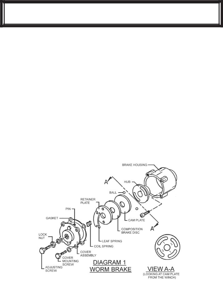
The oil-cooled, fully adjustable, automatic safety brake operates in the worm housing lubricant, all parts being submerged in oil. When the brake wears to the point that the load begins to drift, the brake can be adjusted as follows:
1.Loosen the lock nut on the adjusting screw.
2.Tighten the brake by turning the adjusting screw clockwise.
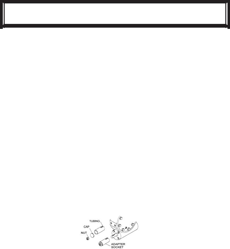
CAUTION: Only 1/4 turn is usually required to adjust the brake. Over-tightening can cause over heating, and damage to the brake parts. Tighten the lock nut after adjustment is completed. If the brake does not respond to adjustment then a new leaf spring and brake disc is needed. A torque wrench can be equipped with a special adapter to fit the input shaft (worm) of the winch. The adapter can be made by welding a nut to the end of a piece of tubing as shown in the following
figure.
After welding the cap and nut to the tubing, slot the tubing as shown. This will allow the special adapter to slide over the keyway and will then act as a large socket. A torque wrench can then be used to apply the proper torque. Turn the torque wrench so that the drum turns in the spool out direction or lowering direction. The torque rating for the Model 200/246 should be 8 to 13ft. lbs. (D-200, 13 to 18ft. lbs.).
If the torque wrench does not show the proper value as it turns the worm brake adjusting bolt should be turned clockwise 1/4 turn. Each time the adjusting bolt is turned, check the torque reading. Continue this procedure until the proper torque reading is achieved. Then tighten the lock nut.
If the torque wrench does not show the proper value as it turns the worm brake adjusting bolt should be turned clockwise 1/4 turn. Each time the adjusting bolt is turned, check the torque reading. Continue this procedure until the proper torque reading is achieved. Then tighten the lock nut.
5
SERVICING OF THE OIL COOLED SAFETY BRAKE
SERVICING OF THE OIL COOLED SAFETY BRAKE
1.Remove the drain plug and drain the worm gear oil from the worm housing.
2.Back off the lock nut, then the adjusting screw, both two turns or more by turning them counter-clockwise.
3.Remove the cover mounting screws.
4.Remove the cover along with coil spring and leaf spring.
5.Remove the retainer plate, composition brake disc, cam plate and balls. Note, the slots the balls are in.
6.Inspect parts as follows:
a). Composition brake discs are 1/8” thick when new. Replace if thinner than 0.080” or if surfaces are glazed or burnt.
b). Inspect the flat, ground surface of the cam plate and retainer plate for glazing, warpage, or other damage. Glazing can be removed by scraping carefully.
c). Inspect the leaf spring. It should be bowed 1/8”.
6

BRAKE - CHECKING / RE-ASSEMBLY AND TESTING
BRAKE RE-ASSEMBLY
1.Press brake hub into place over worm shaft and key.
2.Assemble ball into appropriate slots of cam. (Refer to diagram 1, page 5). Use stiff grease to hold balls into place and slide cam over end of worm. Be sure that balls are secure, between cam slots and hub slots. Refer to Page 7 to determine proper ball slot setting.
3.Install brake disc.
4.Install retainer plate, smooth side toward brake disc.
5.Install the gasket on the cover with a small amount of grease or sealer.
6.The coil spring goes over the adjusting screw on the inside of the cover.
7.Install the notches of the leaf spring on the pins protruding through the cover.
The hollow side of the leaf spring goes toward the brake.
8.Install brake housing cover, making sure the protruding pins go through the leaf spring and into the holes in the retainer plate.
9.Bolt cover into place with the mounting screws. Install drain plug and add 1 pint all purpose EP 140 oil.
10.Turn winch in the hoisting direction at least one turn of the input shaft.
11.Turn the adjusting screw in until it is finger tight.
TEST FOR PROPER BRAKE ASSEMBLY
After the brake has been adjusted to the proper torque setting disengage clutch. Start vehicle engine and run winch in the reel in (hoisting direction). Allow winch to run in this direction for one minute.
Place your hand on the safety brake housing. If housing is not hot to the touch then run winch in the reverse direction (cable out) for one minute. Brake housing should begin to heat.
When these conditions exist, proper installation has been made. If heating becomes noticeable when running the winch in forward rotation (hoisting direction), the brake should be again disassembled. When disassembled, place the brake balls in the alternate set of slots in the cam plate, then carefully follow the instructions for re-assembling and checking the brake.
7
 Loading...