


Ramsey Winch Company
OWNER’S MANUAL
MODEL 800 / H-800 SERIES
DOW-LOK® EQUIPPED
INDUSTRIAL LOW-MOUNT WINCHES
Rated Line Pull (lbs.) |
20,000 |
|
|
|
|
|
|
|
(kg) |
9,060 |
|
|
|
|
|
|
|
Gear Reduction |
40:1 |
|
|
|
|
|
|
|
|
800 |
Y-800 |
H-800 |
HY-800 |
|
|
|
|
Shipping Weight: |
315 lbs. |
290 lbs |
330 lbs. |
325 lbs. |
|
|
|
|
(143 Kg) |
(132 Kg) |
(150 Kg) |
(148 Kg) |
|
|
|
||
|
|
|
|
|||||
Layer of Cable |
|
1 |
2 |
3 |
4 |
5** |
|
|
*Rated line pull per layer |
(lbs.) |
20,000 |
16,600 |
14,200 |
12,400 |
11,000 |
|
|
(kg) |
9,060 |
7,510 |
6,430 |
5,610 |
4,980 |
|
||
|
|
|||||||
*Cable Capacity |
(ft)* |
35 |
75 |
125 |
180 |
240 |
|
|
800 / H-800 |
(m)* |
10 |
22 |
38 |
54 |
72 |
|
|
*Cable Capacity |
(ft)* |
20 |
45 |
75 |
110 |
150 |
|
|
Y-800 / HY-800 |
(m)* |
6 |
13 |
22 |
33 |
45 |
|
|
|
|
|
|
|
|
|
|
|
*Line speed |
|
|
|
|
|
|
Worm |
|
|
|
|
|
|
|
RPM |
||
|
|
|
|
|
|
|
||
800 |
FPM |
22 |
27 |
32 |
35 |
40 |
570 |
|
MPM |
6.6 |
8.1 |
9.7 |
10.9 |
12.3 |
|||
|
|
|||||||
H-800 |
FPM |
18 |
22 |
26 |
29 |
33 |
460 |
|
MPM |
5.4 |
6.6 |
7.9 |
8.8 |
10.0 |
30 GPM |
||
|
||||||||
* These specifications are |
based on |
recommended |
wire rope |
of .63 inch |
(16mm) diameter 6x19 |
|
||
extra improved plow steel cable |
|
|
|
|
|
|
||
** Fifth layer does not conform to SAE J706 |
|
|
|
|
|
|||
|
|
|
|
|
|
|
|
|
Note: The rated line pulls shown are for the winch only. Consult wire rope manufacturer for wire rope ratings
Congratulations
Ramsey Winches are designed and built to exacting specifications. Great care and skill go into every winch we make. If the need should arise, warranty procedure is outlined on the back of your self-addressed postage paid warranty card. Please read and fill out the enclosed warranty card and send it to Ramsey Winch Company. If you have any problems with your winch, please follow instructions for prompt service on all warranty claims. Refer to back page for limited warranty.
CAUTION: READ AND UNDERSTAND THIS MANUAL BEFORE INSTALLATION AND OPERATION OF WINCH. SEE WARNINGS!
1
Contents
Performance Specifications ............................... |
COVER |
Safety Precautions...................................................... |
1 |
Techniques of Operation .......................................... |
2-3 |
Winch Maintenance .................................................... |
3 |
Winch Mounting ......................................................... |
4 |
Cable Installation ........................................................ |
4 |
Adjusting the Oil Cooled |
|
Worm Brake ............................................................... |
4 |
Servicing the Oil Cooled |
|
Worm Brake ............................................................... |
5 |
Re-assembling and |
|
Checking the Brake..................................................... |
5 |
Test for Proper Brake Assembly .................................. |
6 |
Instructions for Checking Assembly Arrangement |
|
and Setting of Worm Brake ........................................ |
6 |
Adjustment of Clutch Air Shifter .................................. |
7 |
Hydraulic System Requirements ................................. |
8 |
Trouble Shooting Guide............................................... |
9 |
|
Instructions for Overhaul ..................................... |
10-16 |
|
Disassembly....................................................... |
10-13 |
|
Re-assembly ...................................................... |
13-16 |
|
Dimensional Drawings |
|
|
Model 800 / Y-800................................................ |
17 |
|
Model H-800 / HY-800.......................................... |
18 |
|
H-800 |
/ HY-800 Short Coupling............................. |
19 |
H-800 |
/ HY-800 Air Shifter .................................... |
20 |
HY-800 Short Coupling/Low Profile Shifter ............ |
21 |
|
Parts List and Parts Drawing |
|
|
Model 800 / Y-800.......................................... |
22-23 |
|
Model H-800 / HY-800.................................... |
24-25 |
|
H-800 |
/ HY-800 SC......................................... |
26-27 |
H-800 |
/ HY-800 Air Shifter .............................. |
38-29 |
Hy-800 Short Coupling/Low Profile Shifter....... |
30-31 |
|
Warranty |
.................................................BACK COVER |
|
Safety Precautions To Guard Against Possible Injury
A.Clutch must be totally engaged before starting the winch operation.
B.Do not disengage clutch under load.
C.Stay out from under and away from raised loads.
D.Stand clear of cable while pulling. Do not try to guide cable.
E.Do not exceed maximum line pull ratings shown in specifications.
F.Do not use winch to lift, support, or otherwise transport people.
G.A minimum of 5 wraps of cable around the drum barrel is necessary to hold load. Cable set screw is not designed to hold load.
1
Techniques of Operation
The best way to get acquainted with how your winch operates is to make test runs before you actually use it. Plan your test in advance. Remember, you hear your winch, as well as see it operate. Get to recognize the sounds of a light steady pull, a heavy pull, and sounds caused by load jerking or shifting. Gain confidence in operating your winch and its use will become second nature with you.
The uneven spooling of cable, while pulling a load, is not a problem, unless there is a cable pileup on one end of drum. If this happens reverse the winch to relieve the load and move your anchor point further to the center of the vehicle. After the job is done you can unspool and rewind for a neat lay of the cable.
The Dow-Lok® clutch provides free spooling and clutch engagement with the cable drum. With the clutch disengaged, the cable can be freespooled off the drum. For winching in the load the clutch must be fully engaged with the drum.
The Dow-Lok® clutch is latched into either the engaged, “IN” position, or the disengaged “OUT” position, by a pin at the bottom of the shifter handle which fits into latching slots.
TO UNLATCH CLUTCH
Run winch in the reverse (reel out) direction until the load is off the cable, Grasp handle firmly and while pushing on the top of the handle with the thumb for leverage, lift until pin clears latching slots.
TO ENGAGE CLUTCH
Unlatch and pull handle toward “IN” position as far as it will go. In order to attain full engagement, internal elements of the clutch must be aligned. This alignment will take place when the cable drum or cable drum shaft turns a maximum of 1/4 revolution. The clutch will automatically spring into engagement and pin will drop into “IN” slots when this alignment takes place. Do not attempt to lift a load unless pin is fully into “IN” slots. Keep clear of spring-loaded handle during automatic engagement.
TO DISENGAGE CLUTCH
Unlatch and push handle to “OUT” position and fully insert pin into latching slots. Do not disengage the clutch under load.
The Dow-Lok® air-shifter clutch provides free spooling and clutch engagement with the cable drum. With the clutch disengaged, the cable can be freespooled off the drum. For winching in the load the clutch must be fully engaged with the drum.
TO ENGAGE CLUTCH
There must be a minimum of 1 foot of slack in the cable before attempting to engage the clutch. This will allow the drum to rotate a minimum of 1/4 turn allowing engagement of the clutch before picking up the load. With this slack in the cable, exhaust air pressure from the air shift cylinder. Run the winch in the “IN” direction until the clutch starts to turn. Clutch must be fully engaged before starting the winch operation.
TO DISENGAGE CLUTCH
Run winch in the “OUT” direction until there is no load on the cable. Apply 70-90 psi to the air shift cylinder to disengage the clutch. Do not disengage the clutch under load.
2
The Dow-Lok® low-profile shifter clutch provides free spooling and clutch engagement with the cable drum. With the clutch disengaged, the cable can be freespooled off the drum. For winching in the load the clutch must be fully engaged with the drum.
TO ENGAGE CLUTCH
Raise the handle so the notch clears the bracket, and pull handle out as far as it will go. The clutch will automatically spring into engagement and latch when the clutch aligns with the drum shaft. In order to attain full engagement, internal elements of the clutch MUST be aligned. This alignment will take place when cable drum or cable drum shaft turns a maximum of 1/4 revolution. Do not attempt to lift a load unless notch in shifter shaft is securely latched. Keep clear of spring-loaded handle during automatic engagement.
TO DISENGAGE CLUTCH
Raise handle so notch clears bracket. Push handle in and latch the shaft notch onto bracket. Do not disengage the clutch under load.
WINCH MAINTENANCE
Adhering to the following maintenance schedule will keep your winch in top condition and performing as it should with a minimum of repair.
A. WEEKLY
1. Check the oil level and maintain it to the oil level plug. If oil is leaking out, determine location and repair.
2. Check the pressure relief plug in top of the gear housing. Be sure that it is in good operating condition so that hot oil gasses may escape.
3. Lubricate cable with light oil.
B. MONTHLY
1.Lubricate the various grease fittings located in the ends of cable drum shaft, end bearing, clutch housing or clutch operating linkage. Any good grade of grease containing moly-disulfide is acceptable.
2.In the case of jaw clutch winches, check the action of the sliding clutch, making sure it is fully engaging and disengaging with the cable drum. Observe the jaws on both the clutch and cable drum, checking for rounding of the driving faces. If rounding has occurred they should be replaced immediately.
3.In the case of Dow-Lok® clutches, check the action of the locking ring. Make sure it is spring loaded and free to move fully against the cable drum in the engaged position and that it is pulled fully away from the cable drum and latched when disengaged.
4.Check the winch mounting bolts. If any are missing, replace them and securely tighten any that are loose. Make sure to use only grade 5 bolts or better.
5.Check the torque setting of the oil cooled worm brake. Make any adjustments required, following the procedure described in ADJUSTING THE OIL COOLED WORM BRAKE in the Owner's Manual.
6.Check alignment of chain and sprockets and adjust as required to minimize wear.
7.Inspect the cable. If the cable has become frayed with broken strands, replace immediately.
C. ANNUALLY
1.Drain the oil from the winch annually or more often if winch is used frequently.
2.Fill the winch to the oil level plug with clean kerosene. Run the winch a few minutes with no load in the reel in direction. Drain the kerosene from the winch.
3.Refill the winch to the oil level plug with all purpose E.P. 140 gear oil.
4.Inspect frame and surrounding structure for cracks or deformation.
5.Gear wear can be estimated by rocking the drum back and forth and if necessary drain oil and remove cover for closer inspection.
3
WINCH MOUNTING
It is most important that this winch be mounted securely so that the three major sections (the clutch housing end, the cable drum and the gear-housing end) are properly aligned.
All standard H-800 Dow-Lok® series winches are furnished with recommended mounting angles. Angle size is 1/2 x 3 x 4 high strength steel angle.
CABLE INSTALLATION
The Ramsey Model H-800 "Dow-Lok"® with the wire rope wound over the drum.
winch has two tapered pockets cast into the drum. One pocket is for installations The other pocket is for an underwound wire rope.
1.Slide the wire rope through narrow end of the pocket against the drum flange.
2.Wrap the wire rope around the anchor "puck" and pull the wire rope and anchor back into the wide end of the pocket.
3.Use a soft hammer to drive the back side of the wire rope, firmly seating the wire rope and anchor, into the pocket. The wire rope can easily be removed from the drum by driving the anchor out the wide end of the pocket.
The Ramsey Model Y-800/HY-800 ("Y" drum) "Dow-Lok"® winch has a setscrew to secure cable to drum.
Insert the end of cable, opposite hook end, into the 11/16" dia. hole in drum barrel. Secure cable to drum barrel, using setscrew furnished with winch. TIGHTEN SETSCREW SECURELY.
Carefully run the winch in the "reel-in" direction, keeping tension on end of cable, spool all the cable onto the cable drum, taking care to form neatly wrapped layers.
ADJUSTING THE OIL COOLED WORM BRAKE
The oil cooled, fully adjustable, automatic worm brake operates in the worm housing lubricant, all parts being submerged in oil. When the brake wears to the point that the load begins to drift, the brake can be adjusted as follows:
1.Loosen the adjusting screw lock nut.
2.Tighten the brake by turning the adjusting screw clockwise. CAUTION: Only 1/4 turn is usually required to adjust the brake. Over-tightening can cause over-heating, and damage to the brake parts. Tighten the lock nut after adjustment is completed.
If the brake does not respond to adjustment then a new leaf spring and brake disc is needed.
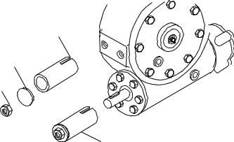
A torque wrench can be equipped with a special adapter to fit the input shaft (worm) of the winch. The adapter can be made by welding a nut to the end of a piece of tubing as shown in the following figure.
After welding the cap and nut to the tubing, slot the tubing, as shown. This will allow the special adapter to slide over the keyway and will then act as a large socket. A torque wrench can the be used to apply the proper torque. Turn the torque wrench so that the drum turns in the spool out direction or lowering direction. The torque rating for the brake on the Model H- 800 Dow-Lok® should be 50 to 55 ft-lbs. If torque wrench does not show the proper value as it turns, then the worm brake adjusting bolt should be turned clockwise 1/4 turn. Each time the adjusting bolt is turned, check the torque reading. Continue this procedure until the proper torque reading is achieved. Then tighten the lock nut.
TUBING
CAP
NUT
ADAPTER SOCKET
4
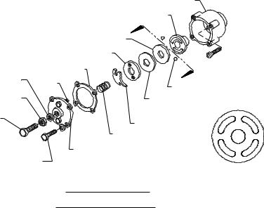
BRAKE HOUSING
A HUB
CAM PLATE
RETAINER PLATE
|
GASKET |
A |
THREAD SEAL |
PIN |
|
|
|
BALL |
JAM NUT
ADJUSTING
SCREW
COVER
MOUNTING
SCREW
COMPOSITION |
|
|
|
BRAKE DISC |
|
|
|
LEAF SPRING |
1 |
2 |
|
COIL SPRING |
|||
|
|||
|
|
||
BRAKE COVER |
2 |
1 |
|
|
|||
|
|
VIEW A-A
DIAGRAM 1 (LOOKING AT CAM PLATE FROM WINCH)
WORM BRAKE
SERVICING OF THE OIL COOLED SAFETY BRAKE
1.Remove the drain plug and drain the worm gear oil from the worm housing.
2.Back off the lock nut, then the adjusting screw, both two turns or more by turning them counter-clockwise.
3.Remove the cover mounting screws.
4.Remove the cover along with coil spring and leaf spring.
5.Remove the retainer plate, composition brake disc, cam plate and balls. Note which slots balls are in.
6.Inspect parts as follows:
a)Composition brake discs are 1/4" thick when new. Replace if thinner than 3/16 or if surfaces are glazed or burnt.
b)Inspect the flat, ground surface of the cam plate and retainer plate for glazing, warpage, or other damage. Glazing can be removed by scraping carefully.
c)Inspect the leaf spring. It should be bowed 1/8".
RE-ASSEMBLING AND CHECKING THE BRAKE
1.Press brake hub into place over worm shaft and key.
2.Assemble balls in appropriate slots of cam. Use stiff grease to hold balls into place and slide cam over end of worm. Be sure that balls are secure, between cam slots and hub slots. See instructions at right to determine proper ball slot setting. Install brake disc.
3.Install retainer plate, smooth side toward brake disc.
4.Install the gasket on the cover with a small amount of grease or sealer.
5.The coil spring goes over the adjusting screw on the inside of the cover.
6.Install the notches of the leaf spring on the pins protruding through the cover. The hollow side of the leaf spring goes toward the brake.
7.Install brake housing cover, making sure the protruding pins go through the leaf spring and into the holes in the retainer plate.
8.Bolt cover into place with the mounting screws. Install drain plug and add 3-3/4 pints all purpose E.P. 140 oil.
9.Turn winch in the hoisting direction at least one turn of the input shaft.
10.Turn the adjusting screw in until it is finger tight.
5
TEST FOR PROPER BRAKE ASSEMBLY
After the brake has been adjusted to the proper torque setting disengage clutch. Start vehicle engine and run winch in the reel in (hoisting direction). Allow winch to run in this direction for one minute.
Place your hand on the safety brake housing. If housing is not hot to the touch then run winch in the reverse direction (cable out) for one minute. Brake housing should begin to heat.
When these conditions exist, proper installation has been made. If heating becomes noticeable when running the winch in forward rotation (hoisting direction), the brake should be again disassembled. When disassembled, place the brake balls in the alternate set of slots in the cam plates, then carefully follow the instructions for re-assembling and checking the brake.
INSTRUCTIONS FOR CHECKING ASSEMBLY ARRANGEMENT AND SETTING OF WORM BRAKE
When the worm brake is assembled the brake must be set with the balls in the #1 or the #2 set of cam slots. (See View A- A, page 6). It is indicated on the name plate whether the balls were installed in the #1 or the #2 slots at the factory.
Three factors determine which slots the balls should be in:
1.Direction cable winds on the drum. It normally winds over the top of the drum barrel.
2.The cut of the gear set, right or left gear. The last letter in the model number of the winch, either R or L, designates right or left gear set. Example: R-20AR, R-30L, 700R, 800L.
3.The side of the winch that the input shaft is on. The Input Shaft is normally toward the cab. Whether the winch has a gear box on the right or the left side of the winch does not affect the brake setting.
When cable winds over the top of the drum, winch has a right cut gear and input shaft is toward the cab, then the balls need to be in the #2 cam slots.
If any one of these three factors differ from those stated above, the balls need to be in the #1 slots in the cam. A second change in these factors requires the original arrangement, and if all three factors are different, the balls need to be in the #1 slots.
6
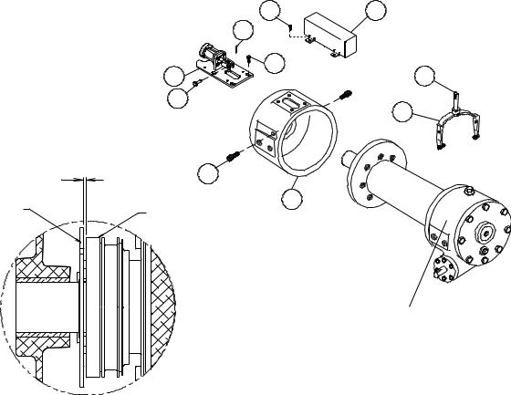
ADJUSTMENT OF CLUTCH AIR SHIFTER
1.Place winch assembly back into mounting frame and reattach using (8) mounting bolts and lockwashers. Torque mounting hardware to 290 ft. lbs. each. Make sure that gear housing and clutch housing are not rubbing against drum flanges.
2.Place air shifter assembly #5 over shifter shaft aligning clevis over flats of shaft. Secure clevis to shaft using clevis pin #76 and cotter pin #75. Place shifter shaft in the "ENGAGED" position. With the air cylinder shaft fully retracted, push shifter assembly toward the drum until all play is taken out of the shifter shaft. Secure shifter assembly to clutch housing using (4) capscrews #46 (flanged hx. hd. serrated). Tighten securely, but do not torque.
3.Hook up air (70 to 90 psi) to inlet port of air cylinder and disengage clutch. Look into the opening in the clutch housing and verify that the locking ring and retainer plate are not making contact. Locking ring and retainer plate must not make contact. There must be a clearance (gap) of .09 inch (max.) between the locking ring and retainer plate when the winch is fully disengaged. If there is contact, the (4) capscrews #46 should be loosened and the plate pulled away from the drum approximately .06 inch. Tighten screws securely and check action to assure needed clearance. Repeat adjustment procedure as needed to acquire needed gap. Shift clutch 2 or 3 times to verify proper shifting of clutch. After final adjustment, torque (4) capscrews #46 to 18 ft. lbs. each. Attach cover #43 using (4) capscrews #61.
61 |
43 |
61 |
|
39 |
34 |
1 |
|
76 |
|
|
37 |
.09 MAX. |
53 |
|
|
||
RETAINER |
21 |
|
LOCKING |
||
PLATE |
||
RING |
||
|
WINCH ASSEMBLY
7

HYDRAULIC SYSTEM REQUIREMENTS
Refer to the performance charts, below, to properly match your hydraulic system to H-800 Dow-Lok® winch performance. The charts consist of :
(1)Line pull (lb.) first layer vs. working pressure (PSI). STATIC (solid line) refers to hoisting a suspended load from rest; DYNAMIC (dotted line) refers to maintaining the motion of a moving load.
(2)Line speed, first layer (FPM) vs. Flow, gallons per minute (GPM).
Performance based on a motor displacement of 14.9 cubic inches with 30 GPM maximum flow rate. See page 18 for motor port size.
H-800, HY-800 Series Performance |
|
|||
20,000 lb. Duty Rating |
40:1 Gear Ratio |
|||
|
20,000 |
|
|
|
|
18,000 |
|
|
|
|
|
C |
|
|
|
16,000 |
I |
C |
|
|
M |
|
||
|
|
A |
I |
|
|
|
N |
T |
|
|
|
A |
|
|
|
|
Y |
|
|
|
|
T |
|
|
|
|
D |
|
|
|
14,000 |
S |
|
|
LAYER |
|
|
|
|
12,000 |
|
|
|
|
FIRST |
|
|
|
|
|
|
|
|
|
LBS., |
10,000 |
|
|
|
PULL,LINE |
8,000 |
|
|
|
|
|
|
|
|
|
6,000 |
|
|
|
|
0 |
1000 |
2000 |
3000 |
WORKING PRESSURE, PSI
TYPICAL HYDRAULIC LAYOUT
CONTROL VALVE
3 POSITION 4 WAY
CYLINDER SPOOL
PUMP INLET LINE
PUMP
RELIEF VALVE
FLUID FILTER
FLUID
RESERVOIR
LOW PRESSURE LINES
8
|
20 |
|
|
|
|
|
|
|
|
|
|
|
|
|
|
|
|
|
|
LAYER |
15 |
|
|
|
|
|
|
|
|
|
|
|
|
|
|
|
|
|
|
|
|
|
|
|
|
|
|
|
|
|
|
|
|
|
|
|
|
||
|
|
|
|
|
|
|
|
|
|
|
|
|
|
|
|
|
|
||
|
|
|
|
|
|
|
|
|
|
|
|
|
|
|
|
|
|
||
|
|
|
|
|
|
|
|
|
|
|
|
|
|
|
|
|
|
||
|
|
|
|
|
|
|
|
|
|
|
|
|
|
|
|
|
|||
|
|
|
|
|
|
|
|
|
|
|
|
|
|
|
|
|
|
|
|
|
|
|
|
|
|
|
|
|
|
|
|
|
|
|
|
|
|
|
|
|
|
|
|
|
|
|
|
|
|
|
|
|
|
|
|
|
|
|
|
|
|
|
|
|
|
|
|
|
|
|
|
|
|
|
|
|
|
|
|
|
|
|
|
|
|
|
|
|
|
|
|
|
|
|
|
|
|
|
|
FPM, FIRST |
10 |
|
|
|
|
|
|
|
|
|
|
|
|
|
|
|
|
|
|
|
|
|
|
|
|
|
|
|
|
|
|
|
|
|
|
|
|
|
|
|
|
|
|
|
|
|
|
|
|
|
|
|
|
|
|
|
|
|
|
|
|
|
|
|
|
|
|
|
|
|
|
|
|
|
|
|
|
|
|
|
|
|
|
|
|
|
|
|
|
|
|
|
|
|
|
|
|
|
|
SPEED,LINE |
5 |
|
|
|
|
|
|
|
|
|
|
|
|
|
|
|
|
|
|
|
|
|
|
|
|
|
|
|
|
|
|
|
|
|
|
|
|
|
|
|
|
|
|
|
|
|
|
|
|
|
|
|
|
|
|
|
|
|
|
|
|
|
|
|
|
|
|
|
|
|
|
|
|
|
|
|
|
|
|
|
|
|
|
|
|
|
|
|
|
|
|
|
|
|
|
|
|
|
|
|
|
|
|
|
|
|
|
|
|
|
|
|
|
|
|
|
|
|
|
|
0 0 |
|
|
|
|
|
|
|
|
|
|
|
|
|
|
|
|||
|
|
|
|
10 |
|
|
|
20 |
|
|
|
30 |
|||||||
|
|
|
|
|
|
|
|
FLOW, GPM |
|
|
|||||||||
HIGH PRESSURE LINES (.88 I.D. MINIMUM)
HYDRAULIC
WINCH MOTOR
LOW PRESSURE LINES (1.31 I.D. MINIMUM)
TROUBLESHOOTING GUIDE
CONDITIONS |
|
POSSIBLE CAUSE |
|
CORRECTION |
|
|
|
|
|
|
|
CLUTCH INOPERATIVE OR BINDS UP |
1. |
Dry or rusted shaft. |
1. |
Clean and Lubricate. |
|
|
2. |
Bent yoke or linkage |
2. |
Replace yoke or shaft assembly. |
|
|
|
|
|
|
|
CLUTCH HANDLE WON’T LATCH |
1. |
Debris in clutch. |
1. |
Clean and lube per page 15. |
|
|
|
|
|
|
|
OIL LEAKS FROM HOUSING |
1. |
Seal damaged or worn. |
1. |
Replace seal. |
|
|
2. |
Too much oil. |
2. |
Drain excess oil. Refer to Tech- |
|
|
|
niques of Operation. |
|||
|
|
|
|
||
|
3. |
Damaged gasket. |
3. |
Replace gasket. |
|
|
|
|
|
|
|
LOAD DRIFTS DOWN |
1. |
Worm brake has become worn. |
1. |
Replace brake disc. (See page 6) |
|
|
2. |
Worm brake out of adjustment. |
2. |
Turn adjusting bolt clockwise 1/4 |
|
|
|
turn or until load does not drift. |
|||
|
|
|
|
||
|
|
|
|
|
|
WINCH RUNS TOO SLOW |
1. |
Hydraulic motor worn out. |
1. |
Replace motor. |
|
|
2. |
Low flow rate. |
2. |
Check flow rate. Refer to Hydraulic |
|
|
|
Systems flow chart, page 8. |
|||
|
|
|
|
||
|
|
|
|
|
|
CABLE DRUM WILL NOT FREESPOOL |
1. |
Winch not mounted squarely, caus- |
1. |
Check mounting. Refer to Winch |
|
|
ing end bearings to bind drum. |
|
Mounting, page 5. |
||
|
|
|
|||
|
|
|
|
|
|
CABLE BIRDNESTS WHEN CLUTCH IS |
1. |
Drag brake disc worn. |
1. |
Replace discs. |
|
DISENGAGED |
|
|
|
|
|
|
|
|
|
|
|
HYDRAULIC FLUID LEAKS FROM |
1. |
Damaged motor shaft seal. |
1. Replace seal. |
||
HOLE IN ADAPTER |
|||||
|
|
|
|
||
|
|
|
|
|
|
9
 Loading...