


43-1085.fm Page 1 Tuesday, August 17, 1999 2:31 PM
Cat. No. 43-1085B
OWNER’S MANUAL
Please read before using this equipment.
ET-910
900 MHz Digital Cordless Speakerphone
With Dual Keypads
43-1085.fm Page 2 Tuesday, August 17, 1999 2:31 PM
FEATURES
Your Radio Shack ET-910 900 MHz Digital Cordless Speakerphone With Dual Keypads uses advanced digital cordless telephone technology to give you superior sound quality. It uses the recently allocated 900 MHz band which means less interference, clearer sound, and greater range than 46/49 MHz cordless telephones. Its cordless operation and dual keypads let you make or answer calls just about anywhere in your home or office. Its features include:
900 MHz Operation — provides better sound and less interference than many other cordless phones.
Digitally Encoded Signal — prevents other people from picking up your phone’s signal and listening to your conversations.
Dual Keypads — a full set of keys on both the ET-910’s handset and base let you use either keypad to make and answer calls or program its features.
Speakerphone — lets you make or answer calls without using the handset.
10-Number Memory Dialing — lets you store up to 10 phone numbers in memory for easy dialing.
Security Access Protection Code
— changes each time you place the handset on the base, to minimize the chances of other cordless phones using your phone line.
10 Channels — scans 10 channels (frequency pairs used between the base and the handset) and automatically selects the one with the least interference each time you make or receive a call, and lets you change the channel during a call.
Out of Range Signal — the handset beeps to let you know when you move out of the base’s operating range.
Two-Way Intercom/Paging System
— lets you send a signal from the base to the handset, or from the handset to the base, so you can page someone or easily locate the handset when it is away from the base. If someone answers, you can use the ET-910 like a two-way intercom.
Any-Key Answer — lets you press any key on the handset (except OFF) to answer an incoming call.
let you adjust the volume of the sound you hear through the handset and the speakerphone.
©1997 Tandy Corporation. All Rights Reserved.
Radio Shack is a registered trademark used by Tandy Corporation.
2
43-1085.fm Page 3 Tuesday, August 17, 1999 2:31 PM
Programmable Ringers — let you select from four ringer types and turn the ringer on or off from both the handset and the speakerphone.
Handset/Base Disable — lets you disable the ET-910’s handset or base during a call to prevent anyone from interrupting your call at the other keypad.
Privacy — prevents the person on the other end of the phone line from hearing your conversation with someone in the room.
Flash — sends an electronic switchhook signal for use with special phone services such as call waiting.
Redial — lets you quickly dial the last number dialed.
Touch Tone (DTMF) or Pulse Dialing — lets you use your phone with either type of dialing.
Hearing Aid Compatible — lets you use this telephone with hearing aids that have a T (telephone) switch.
This phone has been tested and found to comply with all applicable UL and FCC standards.
For your records, we recommend you record the phone’s serial number in the space below. The number is located on the bottom of the base.
Serial Number:
Important: Cordless phones such as this one require AC power to operate. When AC power is off, you cannot dial out or receive incoming calls using your ET-910. For this reason, the ET-910 should not be your only telephone. To be safe, you should also have a phone that does not require AC power to operate (not a cordless phone) so you can still make and receive calls if there is an AC power failure.
Warning: To prevent fire or shock hazard, do not expose this product to rain or moisture.
|
CAUTION |
! |
|
|
|
|
RISK OF ELECTRIC SHOCK. |
|
|
|
|
|
DO NOT OPEN. |
|
|
|
|
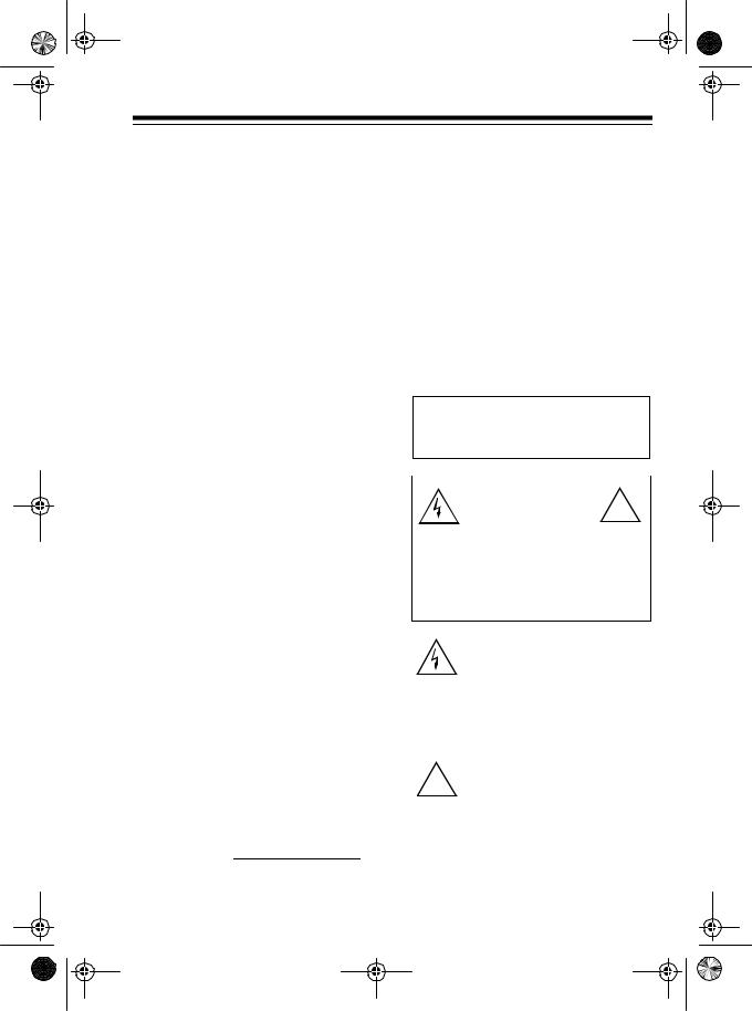
CAUTION: TO REDUCE THE RISK OF ELECTRIC SHOCK, DO NOT REMOVE COVER OR BACK. NO USER-SERVICE- ABLE PARTS INSIDE. REFER SERVICING TO QUALIFIED PERSONNEL.
This symbol is intended to alert you to the presence of uninsulated dangerous voltage within the product’s enclosure that might be of sufficient magnitude to constitute a risk of electric shock. Do not open the product’s case.
This symbol is intended to inform
!you that important operating and maintenance instructions are in-
cluded in the literature accompanying this product.
3

43-1085.fm Page 4 Tuesday, August 17, 1999 2:31 PM
READ THIS BEFORE INSTALLATION
Your telephone conforms to federal regulations, and you can connect it to most telephone lines. However, each device you connect to the phone line draws power from the phone line. We refer to this power draw as the device’s ringer equivalence number, or REN. The REN is on the label on the base’s back.
If you are using more than one phone or other device on the line, add up all the RENs. If the total is more than five, your phone might not ring. In rural areas, a total REN of three might impair ringer operation. If ringer operation is impaired, remove a device from the line.
4
FCC STATEMENT
This telephone complies with Part 68 of FCC Rules. You must, upon request, provide the FCC Registration Number and the REN to your phone company. These numbers are on the label on the base’s back.
You must not connect your phone to any of the following:
•Coin-operated systems
•Party-line systems
•Most electronic key phone systems
Note: Your telephone operates on standard radio frequencies, as allocated by the FCC. Even though the access protection code prevents unauthorized use of your phone line, it is possible for other radio units operating on similar frequencies within a certain area to unintentionally intercept your conversations and/or cause interference. This lack of privacy can occur with any cordless phone.
43-1085.fm Page 5 Tuesday, August 17, 1999 2:31 PM
CONTENTS |
|
Installation ...................................................................................................... |
7 |
Selecting a Location .................................................................................... |
7 |
Placing the Base on a Desktop ................................................................... |
7 |
Mounting the Base on a Wall ....................................................................... |
8 |
Mounting on a Wall Plate ....................................................................... |
8 |
Mounting Directly on the Wall .............................................................. |
10 |
Preparation ................................................................................................... |
12 |
Installing the Battery Pack ......................................................................... |
12 |
Charging the Battery Pack ......................................................................... |
12 |
Setting the PULSE/TONE Switch .............................................................. |
14 |
Adjusting the Ringers ................................................................................ |
14 |
Checking/Setting the Ringer Type ....................................................... |
14 |
Turning On/Off the Base’s Ringer ........................................................ |
15 |
Turning On/Off the Handset’s Ringer ................................................... |
15 |
Operation ...................................................................................................... |
16 |
Making/Answering Calls ............................................................................ |
16 |
Using the Handset ............................................................................... |
16 |
Using the Speakerphone ..................................................................... |
17 |
Switching Between the Handset and Speakerphone ........................... |
18 |
Using Both the Handset and Speakerphone ........................................ |
18 |
Using REDIAL ........................................................................................... |
18 |
Using HOLD .............................................................................................. |
19 |
Using PRIVACY ......................................................................................... |
19 |
Using FLASH ............................................................................................. |
20 |
Using Tone Services on a Pulse Line ........................................................ |
20 |
Changing Channels ................................................................................... |
20 |
Special Features ........................................................................................... |
21 |
Using Memory Dialing ............................................................................... |
21 |
Storing a Number in Memory ............................................................... |
21 |
Storing a Pause in Memory .................................................................. |
22 |
Dialing a Stored Number ...................................................................... |
22 |
Chain Dialing Service Numbers ........................................................... |
23 |
Testing Stored Emergency Numbers ................................................... |
23 |
Using the Intercom .................................................................................... |
23 |
Paging from the Base to the Handset .................................................. |
24 |
Paging from the Handset to the Base .................................................. |
24 |
Using Handset/Base Disable ................................................................ |
25 |
|
5 |
43-1085.fm Page 6 Tuesday, August 17, 1999 2:31 PM
Troubleshooting ........................................................................................... |
26 |
Out of Range Indications ........................................................................... |
29 |
Out of Range with No Call ................................................................... |
29 |
Out of Range with a Call in Progress .................................................. |
29 |
Care and Maintenance ................................................................................. |
30 |
The FCC Wants You to Know .................................................................... |
31 |
Lightning .................................................................................................... |
31 |
6
43-1085.fm Page 7 Tuesday, August 17, 1999 2:31 PM
INSTALLATION
SELECTING A
LOCATION
You can set the ET-910’s base on a flat surface (such as a desktop or counter-top), mount it on a modular jack wall plate, or mount it directly on the wall. The base’s location affects the phone’s range. If you have a choice of several locations, try each to see which one provides the best performance.
Select a location that is:
•Near an AC outlet
•Near a telephone line jack
•Away from electrical machinery, electrical appliances, and metal walls or filing cabinets
•Away from wireless intercoms, alarms, and room monitors
If the phone line jack is not a modular jack, you must update the wiring. You can convert the wiring yourself, using jacks and adapters available at your local Radio Shack store. Or, you can let the phone company update the wiring for you.
Notes:
•The phone company charges for the installation of the necessary jacks.
•The USOC number of the baseboard jack to be installed is RJ11C.
•After you mount the phone, you must install the battery pack and charge it for 24 hours before you use it the first time. See “Preparation” on Page 12.
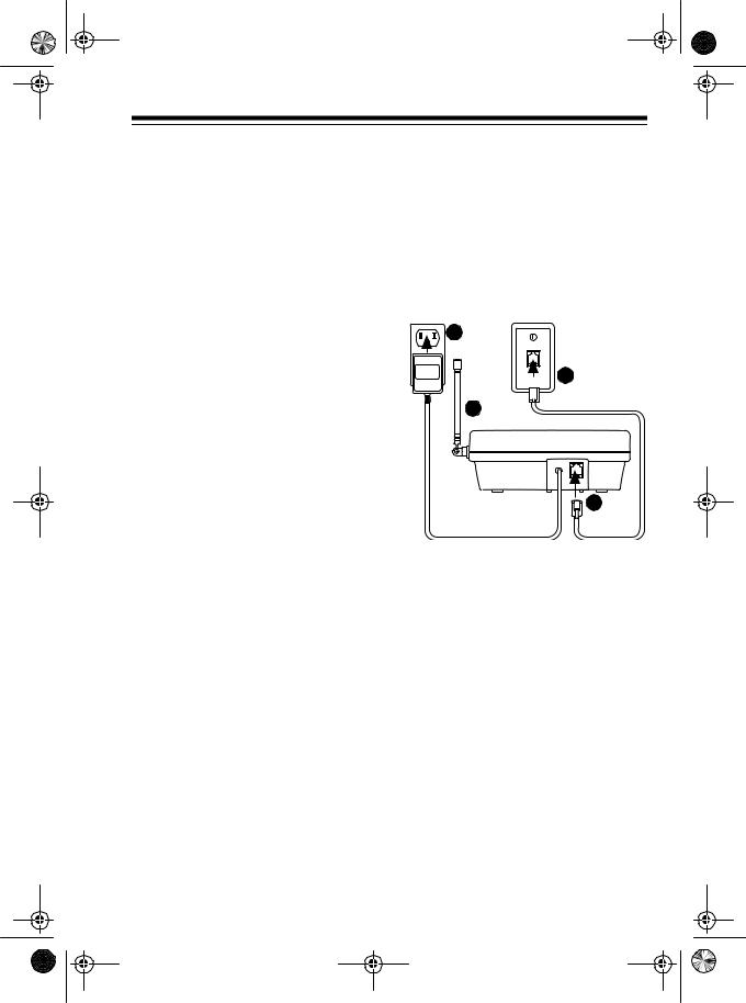
PLACING THE BASE ON A DESKTOP
3 
2 
4 
TO TEL. LINE
1 
1.Plug one end of the supplied 7- foot modular cord into the TO TEL LINE jack on the back of the ET-910’s base.
2.Plug the modular cord’s other end into a modular phone line jack.
3.Plug the ET-910’s AC cord into a standard AC outlet.
4.For the best reception, adjust the base’s antenna so it stands straight up.
7
43-1085.fm Page 8 Tuesday, August 17, 1999 2:31 PM
MOUNTING THE BASE ON A WALL
Using the supplied mounting bracket, you can mount the ET-910’s base on a phone jack wall plate or directly on the wall.
To prepare the bracket for mounting, twist off the tabs attached to the center of the bracket and press them securely into the holes on the narrow end of the bracket.
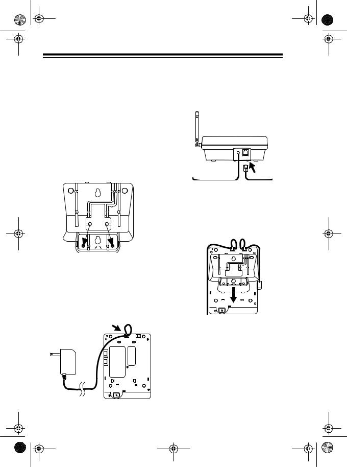
Mounting on a Wall Plate
1.Press the ET-910’s AC cord under the recessed clip directly below it on the bottom of the phone.
8
2.Plug one end of the supplied 7- inch modular cord into the TO TEL LINE jack, then press the cord under the other recessed clip on the bottom of the phone.
TO TEL. LINE
3.Insert the tabs on the supplied mounting bracket into the slots on the base’s bottom. Then press the bracket down until it snaps into place.

43-1085.fm Page 9 Tuesday, August 17, 1999 2:31 PM
4.Press the AC cord into the top and bottom grooves on the left side of the bracket, press the modular cord into the center groove on the right side of the bracket, then plug the modular cord into the modular phone jack.
CORDLESS TELEPHONE ET-910
CHARGE |
HANDSET IN USE |
|
1 |
ABC 2 |
DEF 3 |
GHI 4 |
JKL 5 |
MNO 6 |
PRS 7 |
TUV 8 |
WXY 9 |
TONE |
OPER0 |
# |
7.Plug the ET-910’s AC cord into a standard AC outlet.
8.For the best reception, adjust the base’s antenna so it stands straight up.
5.Line up the keyhole slots on the bracket with the studs on the wall plate, then slide the base down onto the wall plate until it is secure.
6.Press up on the handset holder to remove it, turn it over so its tabbed edge faces up, then press it back down into its slot on the base.
RINGER ON OFF
TONE
PULSE 
Note: If you want to remove the supplied bracket after attaching it, simply press in the tab on each side of the bracket and lift the bracket away from the base.
9
43-1085.fm Page 10 Tuesday, August 17, 1999 2:31 PM
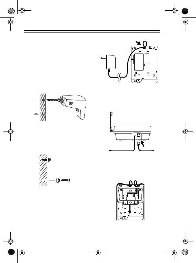
Mounting Directly on the Wall
Using a drill (not supplied) and the supplied screws and spacers, you can easily mount your ET-910 directly on the wall.
1.At the desired mounting location, drill two holes 315/16 inches apart, one above the other.
315/16”
2.Place a spacer over each screw, then thread a screw into each wall hole until the screw’s head extends about 1/4 inch from the wall.
3.Press the ET-910’s AC cord under the recessed clip directly below it on the bottom of the phone.
4.Plug one end of the supplied 7- foot modular cord into the TO TEL LINE jack, then press the cord under the other recessed clip on the bottom of the phone.
TO TEL. LINE
5.Insert the tabs on the supplied mounting bracket into the slots on the base’s bottom, then press the bracket down until it snaps into place.
10
 Loading...