


DSC-200/300
Two Channel RS-422/485 Asynchronous
Communications Adapter
for PCI bus
User's Manual
QUATECH, INC. |
TEL: |
(330) 655-9000 |
5675 Hudson Industrial Parkway |
FAX: |
(330) 655-9010 |
Hudson, Ohio 44236 |
http://www.quatech.com |
|
|
|
|
|
|
|

WARRANTY INFORMATION
Quatech, Inc. warrants the DSC-200/300 to be free of defects for five (5) years from the date of purchase. Quatech, Inc. will repair or replace any board that fails to perform under normal operating conditions and in accordance with the procedures outlined in this document during the warranty period. Any damage that results from improper installation, operation, or general misuse voids all warranty rights.
Please complete the following information and retain for your records. Have this information available when requesting warranty service.
DATE OF PURCHASE:
MODEL NUMBER: |
DSC-200/300 |
PRODUCT DESCRIPTION: Two Channel RS-422/485 Asynchronous
PCI Bus Communications Adapter
SERIAL NUMBER:

(c) 1998 - 2000, Quatech, Inc.
NOTICE
The information contained in this document cannot be reproduced in any form without the written consent of Quatech, Inc. Likewise, any software programs that might accompany this document can be used only in accordance with any license agreement(s) between the purchaser and Quatech, Inc. Quatech, Inc. reserves the right to change this documentation or the product to which it refers at any time and without notice.
The authors have taken due care in the preparation of this document and every attempt has been made to ensure its accuracy and completeness. In no event will Quatech, Inc. be liable for damages of any kind, incidental or consequential, in regard to or arising out of the performance or form of the materials presented in this document or any software programs that might accompany this document.
Quatech, Inc. encourages feedback about this document. Please send any written comments to the Technical Support department at the address listed on the cover page of this document.
DOS, Windows ME, Windows 2000, Windows 98, Windows 95, Windows NT are trademarks or registered trademarks of Microsoft Corporation. OS/2 is a registered trademark of IBM Corporation. All other trademarks or registered trademarks are property of their respective owners.
Declaration of Conformity
Manufacturer's Name: |
Quatech Inc. |
Manufacturer's Address: |
55675 Hudson Industrial Parkway |
|
Hudson, Ohio 44236 (USA) |
Application of Council Directive: |
89/336/EEC |
Standards to which |
|
Conformity is Declared: |
* EN50081-1 (EN55022, |
|
EN60555-2, EN60555-3) |
|
* EN50082-1 (IEC 801-2, |
|
IEC 801-3, & IEC 801-4) |
Type of Equipment: |
Information Technology |
|
Equipment |
Equipment Class: |
Commercial, Residential, & Light |
|
Industrial |
Product Name: |
PCI Dual Serial Communications |
|
Card |
Model Number : |
DSC-200/300 (750,IND) |
. . . . . . . . . . . . . . . . . . . . . . . . . . . . . . . . . . . . . . . . 7
1.1 Features . . . . . . . . . . . . . . . . . . . . . . . . . . . . . . . . . . . . . . . . . . . . . . . . . . . . . . . . 8
. . . . . . . . . . . 8
2 Hardware Configuration . . . . . . . . . . . . . . . . . . . . . . . . . . . . . . . . . |
9 |
|
2.1 |
RS-422 or RS-485 Signal Line Termination . . . . . . . . . . . . . . . . . . |
9 |
2.2 |
Signal Connections . . . . . . . . . . . . . . . . . . . . . . . . . . . . . . . . . . . . . . . . . . . |
10 |
2.3 |
Full-duplex/Half-duplex Operation . . . . . . . . . . . . . . . . . . . . . . . . |
10 |
2.4 |
Clock Rate and Optional Registers . . . . . . . . . . . . . . . . . . . . . . . . . . |
11 |
2.4.1 Enable Scratchpad Register (SPAD, J13) . . . . . . . . . . . . . . . . . |
11 |
|
2.4.2 Force High-Speed UART Clock (X2, X4, or X8, |
|
|
J10-J12) . . . . . . . . . . . . . . . . . . . . . . . . . . . . . . . . . . . . . . . . . . . . . . . . . . . . . . . . . . . |
12 |
|
3 Hardware Installation . . . . . . . . . . . . . . . . . . . . . . . . . . . . . . . . . . . . |
13 |
|
4 Address Map and Special Registers . . . . . . . . . . . . . . . . . |
14 |
|
4.1 |
Base Address and Interrupt Level (IRQ) . . . . . . . . . . . . . . . . . . . |
14 |
4.2 |
Enabling the Special Registers . . . . . . . . . . . . . . . . . . . . . . . . . . . . . . |
15 |
4.3 |
Interrupt Status Register . . . . . . . . . . . . . . . . . . . . . . . . . . . . . . . . . . . . . |
15 |
4.4 |
Options Register . . . . . . . . . . . . . . . . . . . . . . . . . . . . . . . . . . . . . . . . . . . . . . |
16 |
4.4.1 Enhanced Serial Adapter Identification . . . . . . . . . . . . . . . . . |
16 |
|
4.4.2 Clock Rate Multiplier . . . . . . . . . . . . . . . . . . . . . . . . . . . . . . . . . . . . . |
17 |
|
5 Windows Configuration . . . . . . . . . . . . . . . . . . . . . . . . . . . . . . . . . |
18 |
|
5.1 |
Windows Millennium . . . . . . . . . . . . . . . . . . . . . . . . . . . . . . . . . . . . . . . . |
18 |
5.2 |
Windows 2000 . . . . . . . . . . . . . . . . . . . . . . . . . . . . . . . . . . . . . . . . . . . . . . . . |
19 |
5.3 |
Windows 98 . . . . . . . . . . . . . . . . . . . . . . . . . . . . . . . . . . . . . . . . . . . . . . . . . . . |
20 |
5.4 |
Windows 95 . . . . . . . . . . . . . . . . . . . . . . . . . . . . . . . . . . . . . . . . . . . . . . . . . . |
21 |
5.5 |
Using the "New Hardware Found" Wizard . . . . . . . . . . . . . . . . |
23 |
5.6 Windows NT . . . . . . . . . . . . . . . . . . . . . . . . . . . . . . . . . . . . . . . . . . . . . . . . . |
24 |
|
6 DOS and Other Operating Systems . . . . . . . . . . . . . . . . . . |
25 |
|
6.1.1 QTPCI.EXE . . . . . . . . . . . . . . . . . . . . . . . . . . . . . . . . . . . . . . . . . . . . . . . . . |
25 |
|
7 OS/2 . . . . . . . . . . . . . . . . . . . . . . . . . . . . . . . . . . . . . . . . . . . . . . . . . . . . . . . . . . . . |
28 |
|
8 External Connections . . . . . . . . . . . . . . . . . . . . . . . . . . . . . . . . . . . . . |
29 |
|
8.1 |
RTS/cts Handshake . . . . . . . . . . . . . . . . . . . . . . . . . . . . . . . . . . . . . . . . . . |
30 |
8.2 RCLK . . . . . . . . . . . . . . . . . . . . . . . . . . . . . . . . . . . . . . . . . . . . . . . . . . . . . . . . . . |
30 |
|
8.3 XCLK . . . . . . . . . . . . . . . . . . . . . . . . . . . . . . . . . . . . . . . . . . . . . . . . . . . . . . . . . . |
31 |
|
8.4 AUXIN/AUXOUT Loopback . . . . . . . . . . . . . . . . . . . . . . . . . . . . . . . . |
31 |
|
8.5 |
Half-Duplex/Full-Duplex Selection . . . . . . . . . . . . . . . . . . . . . . . . . |
32 |
8.6 Termination Resistors . . . . . . . . . . . . . . . . . . . . . . . . . . . . . . . . . . . . . . . . |
34 |
8.7 RS-422/485 Peripheral Connection . . . . . . . . . . . . . . . . . . . . . . . . . . |
35 |
9 PCI Resource Map . . . . . . . . . . . . . . . . . . . . . . . . . . . . . . . . . . . . . . . . . . |
36 |
10 Specifications . . . . . . . . . . . . . . . . . . . . . . . . . . . . . . . . . . . . . . . . . . . . . . |
37 |
11 Troubleshooting . . . . . . . . . . . . . . . . . . . . . . . . . . . . . . . . . . . . . . . . . |
38 |

1 General Information
The Quatech, Inc. DSC-200/300 provides two RS-422 or RS-485 asynchronous serial communication interfaces for IBM-compatible personal computer systems using the PCI expansion bus. The DSC-200/300 uses Quatech's new Enhanced Serial Adapter design. Legacy serial port data rates are limited to a maximum of 115,200 bits per second. Quatech Enhanced Serial Adapters can achieve data rates as high as 921,600 bits per second.
As a PCI device, the DSC-200/300 requires no hardware configuration. The card is automatically configured by the computer's BIOS or operating system. The two serial ports share a single interrupt line and are addressed in a contiguous block of 16 bytes. A special interrupt status register is provided to help software to manage the shared interrupt.
The DSC-200/300's serial ports are using 16750 Universal Asynchronous Receiver/Transmitters (UARTs). These UARTs contain hardware buffers (FIFOs) which reduce processing overhead and allow higher data rates to be achieved. The 16750 contains a 64-byte FIFO and can transmit and receive data at a rate of up to 921,600 bits per second. The 16750 is recommended for heavy multitasking environments and for applications involving high data rates.
The DSC-200/300 is supported under several popular operating systems and environments. Contact the sales department for details on current software offerings. Most device drivers are available for download from the Quatech world wide web site at http://www.quatech.com.
Quatech DSC-200/300 User's Manual |
7 |
1.1 Features
The standard DSC-200/300 implements each of its communication channels with a 16750 UART and uses standard line driver and receiver components. For improved performance and industrial-grade reliability.
1.1.1 "IND" Option --- Surge Suppression Upgrade
The "IND" upgrade provides the protection essential for reliable use in an industrial environment. Each communication line has a surge suppressor capable of sustaining up to 40A 20us peak transient surges, a clamping voltage of 30V and a peak energy dissipation of 0.1 Joules.
Quatech DSC-200/300 User's Manual |
8 |
2 Hardware Configuration
The DSC-200/300 is automatically configured at boot time by the computer's BIOS or operating system. There are no required switches or jumpers to set for installation.
This chapter lists a number of jumper settings that control various hardware features. Jumpers J1-J4, located in a column near the D-9 connectors, control the RS-422 or RS-485 signal line termination. Jumpers J5-J8, located in a column just to the right of J1-J4, control how signals are routed from the UARTs to the connector, as well as fullor halfduplex operation. Jumpers J10-J13, grouped together at the end of the board opposite the D-9 connectors, control special options.
Any changes from the factory default should be made before installing the DSC-200/300 in the computer.
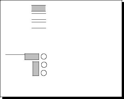
2.1 RS-422 or RS-485 Signal Line Termination
Jumpers J1-J4 allow the selection of 100-ohm RS-422 termination, 120-ohm RS-485 termination, or no termination at all. The factory default, shown in Figure 1, is RS-422 termination. For full details, see page 24.
Jumpers J1-J4
3
2
1
RS-422 termination (100 ohms)
(factory default)
Figure 1 --- Factory default signal termination settings
Quatech DSC-200/300 User's Manual |
9 |
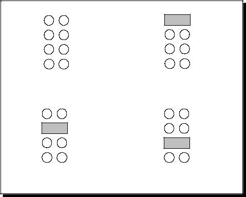
2.2 Signal Connections
The DSC-200/300 provides each of two serial ports with four differential signal pairs: TxD, RxD, AUXOUT, and AUXIN. TxD and RxD are always present at the connector. The AUXOUT and AUXIN signals can be used to support RTS/CTS handshaking, external clocking, or external signal loopback. The factory default configuration, as shown in Figure 2, is a loopback of AUXOUT to AUXIN at the connector, with RTS and CTS looped back on the board. There is an extensive discussion of this topic starting on page 19.
2.3 Full-duplex/Half-duplex Operation
The DTR or RTS modem control output of the UART can be used to enable and disable the transmit drivers. The inverse of these signals can also be used to enable and disable the receivers. These options are selectable per channel. The factory default, as shown in Figure 2, is for both the drivers and receivers of both channels to be continuously enabled. Two spare jumpers are installed in neutral positions. For details, refer to page 22.
The DSC-200/300 is shipped from the factory with each channel configured as shown in Figure 2.
XCLK 6 
 3 RCLK
AUXOUT 5  2 AUXIN
RTS 4 
 1 CTS
1 CTS
Loopback RTS to CTS Loopback AUXOUT to AUXIN
Loopback XCLK to RCLK
Jumpers J5, J7
Tx ENABLE6 |
3 |
Rx ENABLE |
|
Tx |
ENABLE5 |
2 |
Jumpers J6, J8 |
RTS |
|||
Tx |
ENABLE4 |
1 |
DTR |
Full Duplex Operation (spare jumpers supplied)
Figure 2 --- Factory default signal interface settings
Quatech DSC-200/300 User's Manual |
10 |
2.4 Clock Rate and Optional Registers
Figure 3 shows the jumper configuration as shipped from the factory, with two spare jumpers applied in neutral positions. Remove one or both and apply as shown in following subsections to set optional features.
J10 |
X2 |
J11 |
X4 |
J12 |
X8 |
J13 |
SPAD |
Figure 3 --- Factory default clock rate and options settings
2.4.1 Enable Scratchpad Register (SPAD, J13)
In the default configuration, an Interrupt Status Register and an Options Register (see page 10) replace the scratchpad (base address + 7) of each UART. If the SPAD jumper is applied as in Figure 4, the UART scratchpad registers are enabled, and the Interrupt Status Register and the Options Register are not available.
J10 |
X2 |
J11 |
X4 |
J12 |
X8 |
J13 |
SPAD |
Figure 4 --- Enable scratchpad registers
Quatech DSC-200/300 User's Manual |
11 |
2.4.2 Force High-Speed UART Clock (X2, X4, or X8, J10-J12)
These jumpers force an increase of the UART input clock frequency by a factor of two, four, or eight. This feature can allow legacy software to use baud rates above 115,200 bits per second. It is also useful if the serial port device driver does not directly support setting the higher baud rates through the Options Register (see page 10).
If one of these jumpers is applied, it overrides any value written to the Options Register to set the clock multiplier by software. The effective baud rate will be either two, four, or eight times the value for which the UART itself is programmed.
The factory default is none of these jumpers applied, which allows for software control of the clock multiplier via the Options Register. The Options Register powerup default is for a standard times-1 clock of 1.8432 MHz for compatibility with standard serial ports.
J10 |
X2 |
J10 |
X2 |
J11 |
X4 |
J11 |
X4 |
J12 |
X8 |
J12 |
X8 |
J13 |
SPAD |
J13 |
SPAD |
Factory default |
Force times-two clock |
||
software control |
Baud rates up to 230.4 kbps |
||
J10 |
X2 |
J10 |
X2 |
J11 |
X4 |
J11 |
X4 |
J12 |
X8 |
J12 |
X8 |
J13 |
SPAD |
J13 |
SPAD |
Force times-four clock |
Force times-eight clock |
||
Baud rates up to 460.8 kbps |
Baud rates up to 921.6 kbps |
||
Figure 5 --- Clock multiplier jumper options
Quatech DSC-200/300 User's Manual |
12 |
 Loading...