


ATL M-Series
User’s Guide
6423002-03
Ver. 3, Rel. 0
ATL M-Series User’s Guide, 6423002-03, Ver. 3, Rel. 0, January 2003, Made in USA.
Quantum Corporation provides this publication “as is” without warranty of any kind, either express or implied, including but not limited to the implied warranties of merchantability or fitness for a particular purpose. Quantum Corporation may revise this publication from time to time without notice.
COPYRIGHT STATEMENT
© Copyright 2003 by Quantum Corporation. All rights reserved.
Your right to copy this document is limited by copyright law. Making copies or adaptations without prior written authorization of Quantum Corporation is prohibited by law and constitutes a punishable violation of the law.
TRADEMARK STATEMENT
StackLink is a trademark of Quantum Corporation.
Other trademarks may be mentioned herein which belong to other companies.
6207947-07cN 111

Contents
Preface |
|
xiii |
Chapter 1 |
Overview |
1 |
|
Library Capacity ..................................................................................... |
1 |
|
ATL M1500 Library ......................................................................... |
1 |
|
ATL M2500 Library ......................................................................... |
1 |
|
SCSI Configuration................................................................................. |
2 |
|
Library Scalability .................................................................................. |
2 |
|
Library Features...................................................................................... |
5 |
|
Front Panel ........................................................................................ |
5 |
|
Internal Layout................................................................................. |
8 |
|
Back Panel ....................................................................................... |
10 |
Chapter 2 |
Basic Operations |
13 |
|
Introduction........................................................................................... |
14 |
|
Main Screen..................................................................................... |
14 |
|
GUI Buttons .................................................................................... |
17 |
|
GUI Icons......................................................................................... |
18 |
ATL M-Series User’s Guide |
iii |

Contents |
|
|
|
Using the Quick View Menu Screen.................................................. |
19 |
|
Accessing the Quick View Menu Screen .................................... |
20 |
|
Viewing Library Information ....................................................... |
20 |
|
Viewing Tape Drive Information ................................................ |
22 |
|
Viewing Inventory Information................................................... |
23 |
|
Turning Drive Power On or Off (Quick View Menu Screen).. |
24 |
|
Moving Tape Cartridges...................................................................... |
26 |
|
Using the Mailbox ................................................................................ |
30 |
|
Viewing Mailbox Status ................................................................ |
31 |
|
Importing and Exporting Cartridges .......................................... |
31 |
|
Configuring the Mailbox............................................................... |
37 |
|
Removing the Magazines .................................................................... |
38 |
|
Removing a Magazine from an ATL M1500 .............................. |
38 |
|
Removing a Magazine from an ATL M2500 .............................. |
41 |
|
Viewing Statistics.................................................................................. |
46 |
|
Accessing the Statistics Menu Screen.......................................... |
46 |
|
Viewing Library Statistics............................................................. |
47 |
|
Viewing Drive Statistics ................................................................ |
48 |
|
Viewing the SCSI History ............................................................. |
49 |
|
Viewing the Stack Configuration ....................................................... |
50 |
Chapter 3 |
Changing the Library Configuration |
53 |
|
Accessing the Configuration Screen .................................................. |
53 |
|
Setting the Library ID........................................................................... |
55 |
|
Changing a Tape Drive ID .................................................................. |
56 |
|
Changing the Terminator Power Setting .......................................... |
58 |
|
Changing the Emulation Setting ........................................................ |
59 |
|
Changing the Sync Negotiation Setting ............................................ |
60 |
|
Changing the Wide Negotiation Setting ........................................... |
61 |
|
Changing the Serialization Setting..................................................... |
62 |
|
Changing the Short Labels Setting..................................................... |
63 |
|
Changing the Illumination Setting..................................................... |
64 |
|
Changing the Off-Line Time Setting.................................................. |
65 |
|
Changing the Barcode Scanner Setting ............................................. |
66 |
iv |
ATL M-Series User’s Guide |

|
|
Contents |
|
Changing the Baud Rate Setting ........................................................ |
67 |
|
Setting the Time .................................................................................... |
67 |
|
Setting the Date..................................................................................... |
68 |
|
Changing the Import/Export Setting................................................ |
69 |
|
Changing the Auto-Clean Setting ...................................................... |
72 |
|
Changing the Ignore Host Lock Setting............................................ |
73 |
|
Changing the Auto-Import Option.................................................... |
74 |
Chapter 4 |
Performing Maintenance Operations |
77 |
|
Accessing the Maintenance Screen .................................................... |
77 |
|
Cleaning a Tape Drive ......................................................................... |
79 |
|
Turning Drive Power On or Off (Maintenance Screen).................. |
81 |
|
Adjusting the Contrast......................................................................... |
83 |
Chapter 5 |
Running Diagnostic Programs |
85 |
|
Accessing the Diagnostics Menu Screen ........................................... |
85 |
|
Running the Barcode Scanner Test .................................................... |
87 |
|
Running the Move Medium Test ....................................................... |
89 |
|
Running the Move Location Test ....................................................... |
92 |
|
Running the Display Test.................................................................... |
95 |
Chapter 6 |
Running the Demonstration Programs |
97 |
|
Accessing the Demo Programs Screen .............................................. |
97 |
|
Running the Confidence Test Program............................................. |
98 |
|
Running the Demo 1 Program............................................................ |
99 |
|
Running the Demo 2 Program.......................................................... |
100 |
|
Running the Demo 3 Program.......................................................... |
101 |
|
Running the Demo 4 Program.......................................................... |
102 |
|
Running the Demo 5 Program.......................................................... |
103 |
|
Running the Demo 6 Program.......................................................... |
104 |
ATL M-Series User’s Guide |
v |

Contents |
|
|
Appendix A |
Specifications |
105 |
|
Physical Specifications ....................................................................... |
106 |
|
Performance Specifications ............................................................... |
108 |
|
Reliability Specifications.................................................................... |
110 |
|
Tape Drive Specifications .................................................................. |
110 |
|
Environmental Specifications ........................................................... |
111 |
Appendix B |
Fault Symptom Code (FSC) Dictionary |
113 |
Appendix C |
DLTtape Cartridge Maintenance |
161 |
|
Handling DLTtape Cartridges.......................................................... |
161 |
|
Visual Inspection of DLTtape Cartridges ....................................... |
162 |
|
When To Visually Inspect a DLTtape Cartridge ..................... |
162 |
|
Visual Inspection Procedure....................................................... |
163 |
Appendix D |
Regulatory Statements |
167 |
Glossary |
|
199 |
Index |
|
201 |
vi |
ATL M-Series User’s Guide |

Figures
Figure 1 |
ATL M1500 Front Panel ..................................................... |
5 |
Figure 2 |
ATL M2500 Front Panel ..................................................... |
6 |
Figure 3 |
ATL M1500 Internal Layout .............................................. |
8 |
Figure 4 |
ATL M2500 Internal Layout .............................................. |
9 |
Figure 5 |
ATL M1500 Back Panel .................................................... |
10 |
Figure 6 |
ATL M2500 Back Panel .................................................... |
11 |
Figure 7 |
Sample Main Screen, Stand-alone ATL M1500 ............ |
15 |
Figure 8 |
Sample Main Screen, ATL M1500 in a Multiple |
|
|
Library Stack...................................................................... |
16 |
Figure 9 |
ATL M2500 Library Levels.............................................. |
16 |
Figure 10 |
Sample Main Screen, ATL M2500................................... |
17 |
Figure 11 |
Using the GUI Buttons ..................................................... |
17 |
Figure 12 |
Quick View Menu Screen ................................................ |
20 |
Figure 13 |
Sample Library Information Screen ............................... |
21 |
Figure 14 |
Sample Drive Information Screen .................................. |
22 |
Figure 15 |
Sample Inventory Screen ................................................. |
23 |
ATL M-Series User’s Guide |
vii |
Figures
Figure 16 Sample Tape Drive Power Screen .................................. |
24 |
|
Figure 17 Sample Drive Power Screen ............................................ |
25 |
|
Figure 18 |
Menu Screen ...................................................................... |
26 |
Figure 19 Sample Move Cartridge FROM Screen.......................... |
27 |
|
Figure 20 Sample Move Cartridge TO Screen................................ |
28 |
|
Figure 21 Sample Confirm Move Cartridge Screen....................... |
29 |
|
Figure 22 Sample Mailbox Screen .................................................... |
30 |
|
Figure 23 |
Mailbox - OPEN Screen.................................................... |
32 |
Figure 24 Sample Release Magazines Screen ................................. |
39 |
|
Figure 25 Magazine Release Button................................................. |
40 |
|
Figure 26 Release Magazines Screen ............................................... |
41 |
|
Figure 27 Removing the Level 2 Left Magazine ............................ |
43 |
|
Figure 28 |
Release Latch ..................................................................... |
44 |
Figure 29 Removing the Level 1 Left Magazine ............................ |
45 |
|
Figure 30 Service Menu Screen......................................................... |
46 |
|
Figure 31 Statistics Menu Screen...................................................... |
47 |
|
Figure 32 Sample Library Statistics Screen ..................................... |
47 |
|
Figure 33 Sample Drive Statistics Screen ........................................ |
49 |
|
Figure 34 Sample SCSI History Screen............................................ |
50 |
|
Figure 35 Sample Stack Configuration Screen ............................... |
51 |
|
Figure 36 |
Menu Screen ...................................................................... |
54 |
Figure 37 |
Configuration Screen........................................................ |
54 |
Figure 38 ATL M2500 Drive Numbering........................................ |
56 |
|
Figure 39 Service Menu Screen......................................................... |
78 |
|
Figure 40 |
Maintenance Screen .......................................................... |
78 |
Figure 41 Sample Select Cleaning Cartridge Screen ..................... |
79 |
|
Figure 42 Sample Select Tape Drive Screen.................................... |
80 |
|
viii |
ATL M-Series User’s Guide |
|
Figures |
Figure 43 Sample Tape Drive Power Screen .................................. |
81 |
Figure 44 Drive Power Screen .......................................................... |
82 |
Figure 45 Adjust Contrast Screen..................................................... |
83 |
Figure 46 Service Menu Screen......................................................... |
86 |
Figure 47 Diagnostics Menu Screen................................................. |
86 |
Figure 48 Diags: General Screen....................................................... |
87 |
Figure 49 Diag: Barcode Screen........................................................ |
88 |
Figure 50 Sample Move Cartridge FROM Screen.......................... |
89 |
Figure 51 Sample Move Cartridge TO Screen................................ |
90 |
Figure 52 Sample Confirm Move Cartridge Screen ...................... |
91 |
Figure 53 Diag: Move Medium Screen............................................ |
91 |
Figure 54 Sample Diag: Move-Location Screen ............................. |
93 |
Figure 55 Diag: Move Location Screen............................................ |
94 |
Figure 56 Demo Programs Screen.................................................... |
98 |
Figure 57 Location of the Reel Locks and the Hub...................... |
163 |
Figure 58 Opening the Tape Cartridge Door ............................... |
164 |
Figure 59 Write Protect Switch....................................................... |
165 |
Figure 60 Declaration of Conformity, ATL M1500...................... |
196 |
Figure 61 Declaration of Conformity, ATL M2500...................... |
197 |
ATL M-Series User’s Guide |
ix |
Figures
x |
ATL M-Series User’s Guide |
Tables
Table 1 |
Capacity, ATL M1500 Multiple Library Stack |
................3 |
Table 2 |
Capacity, ATL M2500 Multiple Library Stack................ |
4 |
Table 3 |
Front Panel Features........................................................... |
7 |
Table 4 |
GUI Icons ........................................................................... |
18 |
Table 5 |
Import/Export Settings.................................................... |
70 |
Table 6 |
Unit Dimensions/Weight.............................................. |
106 |
Table 7 |
Capacities ......................................................................... |
106 |
Table 8 |
Performance Specifications ........................................... |
108 |
Table 9 |
Library Performance....................................................... |
108 |
Table 10 |
Reliability Specifications................................................ |
110 |
Table 11 |
Tape Drive Specifications .............................................. |
110 |
Table 12 |
Power................................................................................ |
111 |
Table 13 |
Climate ............................................................................. |
111 |
Table 14 |
Compliance and Certification ....................................... |
111 |
Table 15 |
Fault Symptom Codes.................................................... |
113 |
ATL M-Series User’s Guide |
xi |
Tables
xii |
ATL M-Series User’s Guide |

Preface
Audience
Purpose
Document
Organization
This document is written for operators of the ATL M1500 and ATL M2500 libraries.
This document explains how to use the ATL M1500 and ATL M2500 libraries.
This document is organized as follows:
•Chapter 1, Overview, provides an overview of the ATL M-Series libraries.
•Chapter 2, Basic Operations, introduces the library GUI screens and explains how to use them to perform basic library operations such as moving tape cartridges within the library, removing the tape cartridge magazines, and viewing library information.
•Chapter 3, Changing the Library Configuration, explains how to change the library configuration using the GUI
Configuration screen.
ATL M-Series User’s Guide |
xiii |
Preface
•Chapter 4, Performing Maintenance Operations, explains how to perform library maintenance operations using the GUI
Maintenance screen.
•Chapter 5, Running Diagnostic Programs, explains how to use the library’s built in diagnostic programs.
•Chapter 6, Running the Demonstration Programs, explains how to run the library demonstration programs.
•Appendix A, Specifications, lists the specifications for the ATL M-Series libraries.
•Appendix B, Fault Symptom Code (FSC) Dictionary, lists the fault symptom codes (FSCs) for the ATL M-Series libraries.
•Appendix C, DLTtape Cartridge Maintenance, provides guidelines for handling DLT cartridges and visually inspecting them if necessary.
•Appendix D, Regulatory Statements, provides regulatory information for the ATL M-Series libraries.
This document concludes with a glossary and a detailed index.
Notational |
|
This document uses the following conventions: |
|
Conventions |
|
|
|
|
|
Note: Notes emphasize important information related to the |
|
|
|
main topic. |
|
|
|
|
|
|
|
|
|
|
|
Tech Tip: |
Tech Tips provide technical information that may be |
|
|
|
helpful in performing the procedure. |
|
|
|
|
|
|
|
|
|
|
|
|
|
|
Caution: |
Cautions indicate potential hazards to equipment |
|
|
|
and are included to prevent damage to equipment. |
|
|
|
|
|
|
|
|
|
|
|
|
|
|
Warning: |
Warnings indicate potential hazards to personal |
|
|
|
safety and are included to prevent injury. |
|
|
|
|
|
|
|
|
xiv |
ATL M-Series User’s Guide |
Preface
This manual uses the following:
•Right side of the library — Refers to the right side as you face the component being described.
•Left side of the library — Refers to the left side as you face the component being described.
Related |
|
Documents related to the ATL M-Series libraries are shown below. |
||
Documents |
|
|
|
|
|
|
ATL M-Series Documentation |
|
|
|
|
|
|
|
|
|
Document No. |
Title |
Description |
|
|
|
|
|
|
6421002 |
ATL M1500 Unpacking |
This document explains |
|
|
|
|
Instructions |
how to remove the |
|
|
|
|
ATL M1500 library from |
|
|
|
|
the shipping carton. |
|
|
|
|
|
|
6423000 |
ATL M2500 Unpacking |
This document explains |
|
|
|
|
Instructions |
how to remove the |
|
|
|
|
ATL M2500 library from |
|
|
|
|
the shipping carton. |
|
|
|
|
|
|
6423001 |
ATL M-Series Installation |
This document explains |
|
|
|
|
Guide |
how to install an |
|
|
|
|
ATL M-Series library. |
|
|
|
|
|
|
6421011 |
ATL M1500 Regulatory |
This document provides |
|
|
|
|
Statements |
regulatory information |
|
|
|
|
for the ATL M1500 |
|
|
|
|
library. |
|
|
|
|
|
|
6423004 |
ATL M2500 Regulatory |
This document provides |
|
|
|
|
Statements |
regulatory information |
|
|
|
|
for the ATL M2500 |
|
|
|
|
library. |
|
|
|
|
|
ATL M-Series User’s Guide |
xv |
Preface
Refer to the appropriate product manuals for information about your tape drive and cartridges.
SCSI-2 Specification
The SCSI-2 communications specification is the proposed American National Standard for information systems, dated March 9, 1990. Copies may be obtained from:
Global Engineering Documents 15 Inverness Way, East Englewood, CO 80112
(800) 854-7179 or (303) 397-2740
Contacts |
Quantum company contacts are listed below. |
Quantum Corporation
To order documentation on the ATL M-Series libraries or other products contact:
Quantum P.O. Box 57100
Irvine, CA 92619-7100 (949) 856-7800 (800) 284-5101
Technical Publications
To comment on existing documentation send e-mail to:
doc-comments@quantum.com
xvi |
ATL M-Series User’s Guide |
Preface
Web Site
Visit the Quantum web site at:
http://www.quantum.com
Customer Support
The Customer Support Department provides a 24-hour help desk that can be reached at:
North/South America: |
(949) 725-2100 or |
|
(800) 284-5101 |
Asia/Pacific Rim: |
(International Code) |
|
+61 7 3839 0988 |
Europe/Middle East/Africa: (International Code) +44 (0) 1256 848748
Send faxes for the Customer Support Department to:
North/South America: |
(949) 725-2176 |
Asia/Pacific Rim: |
(International Code) |
|
+61 7 3839 0955 |
Europe/Middle East/Africa: (International Code) + +44 (0) 1256 848777
Send e-mail for the Customer Support Department to:
North/South America: |
helpdesk@quantum.com |
Asia/Pacific Rim: |
apachelp@quantum.com |
Europe/Middle East/Africa: eurohelp@quantum.com
ATL M-Series User’s Guide |
xvii |
Preface
xviii |
ATL M-Series User’s Guide |

Chapter 1
1Overview
This chapter provides an overview of the ATL M-Series libraries and their features.
Library Capacity
ATL M1500
Library
ATL M2500
Library
The ATL M1500 library can contain up to two tape drives and up to 21 DLT/SDLT cartridges or 25 LTO cartridges. The cartridges are stored in two independently removable cartridge magazines and one fixed cartridge slot.
The ATL M2500 library can contain:
•Up to five tape drives and up to 84 DLT/SDLT cartridges or 100 LTO cartridges
•Six tape drives and up to 73 DLT/SDLT cartridges or 87 LTO cartridges
ATL M-Series User’s Guide |
1 |

Chapter 1 Overview
SCSI Configuration
The cartridges are stored in up to eight independently removable cartridge magazines and up to four fixed cartridge slots.
SCSI Configuration
The ATL M1500 and ATL M2500 library modules come configured for LVD SCSI. One SCSI bus is provided for the library robotics and for each tape drive installed. These SCSI buses are SCSI-2 fast/ wide (8/16 bit), Ultra SCSI, Ultra 2 SCSI, or Ultra 3 SCSI, depending on the drives installed.
Library Scalability
The ATL M1500 and ATL M2500 library modules can be used as stand-alone libraries, or can be combined with other ATL M1500 and ATL M2500 library modules and a StackLink mechanism in a standard 19-inch rack to form a larger library system (called a multiple library stack). The multiple library stack appears as a single large capacity library to the host.
The StackLink mechanism connects the library modules in the multiple library stack and transports cartridges from module to module. Each tape drive has access to all the tape cartridges in the stack.
Once the StackLink mechanism is installed in the rack, you can add library modules simply by sliding them into place and making the necessary electrical connections.
Table 1 lists the capacities of all the sizes of multiple library stack you can create using ATL M1500 library modules. Table 2 lists the capacities of all the sizes of multiple library stack you can create using ATL M2500 library modules. You can obtain different capacities by combining ATL M1500 and ATL M2500 library modules in a multiple library stack.
2 |
ATL M-Series User’s Guide |
Chapter 1 Overview
Library Scalability
Table 1 |
Capacity, |
|
|
|
|
|
|
|
|
|
|
|
|
|
|||
ATL M1500 Multiple |
|
|
|
|
|
|
|
|
|
|
|
|
|||||
Library Stack |
|
|
|
|
|
|
|
|
|
|
|
|
|
|
|
||
|
|
|
|
|
|
|
|
|
|
|
|
|
|
|
|
|
|
Modules |
|
|
# of |
|
|
|
|
|
|
|
|
|
|
|
|
||
|
|
Cartridges* |
|
|
|
|
Capacity (in TB)* |
|
|
|
|||||||
|
|
|
|
|
|
|
|
|
|
||||||||
Library |
|
Drives |
|
|
|
|
|
|
|
|
|
|
|
HP LTO |
HP LTO |
||
|
|
|
|
|
DLT 8000 |
SDLT 220 |
|
SDLT 320 |
Gen 1 |
Gen 2 |
|||||||
|
|
|
|
|
|
|
|
||||||||||
# of ATL M1500 |
|
Max. # of Tape |
|
|
|
|
|
|
|
|
|
|
|
|
|
|
|
|
|
|
|
|
|
† |
|
† |
|
|
† |
|
† |
|
† |
||
|
DLT/SDLT |
|
LTO |
Native |
Compressed |
Native |
Compressed |
|
Native |
Compressed |
Native |
Compressed |
Native |
Compressed |
|||
|
|
|
|
|
|
|
|
|
|
|
|
|
|
|
|
|
|
1 |
|
2 |
21 |
|
|
25 |
0.8 |
1.7 |
2.3 |
4.6 |
|
3.4 |
6.7 |
2.5 |
5.0 |
5.0 |
10.0 |
|
|
|
|
|
|
|
|
|
|
|
|
|
|
|
|
|
|
2 |
|
4 |
42 |
|
|
50 |
1.7 |
3.4 |
4.6 |
9.2 |
|
6.7 |
13.4 |
5.0 |
10.0 |
10.0 |
20.0 |
|
|
|
|
|
|
|
|
|
|
|
|
|
|
|
|
|
|
3 |
|
6 |
63 |
|
|
75 |
2.5 |
5.0 |
6.9 |
13.9 |
|
10.1 |
20.2 |
7.5 |
15.0 |
15.0 |
30.0 |
|
|
|
|
|
|
|
|
|
|
|
|
|
|
|
|
|
|
4 |
|
8 |
84 |
|
|
100 |
3.4 |
6.7 |
9.2 |
18.5 |
|
13.4 |
26.9 |
10.0 |
20.0 |
20.0 |
40.0 |
|
|
|
|
|
|
|
|
|
|
|
|
|
|
|
|
|
|
5 |
|
10 |
105 |
|
|
125 |
4.2 |
8.4 |
11.6 |
23.1 |
|
16.8 |
33.6 |
12.5 |
25.0 |
25.0 |
50.0 |
|
|
|
|
|
|
|
|
|
|
|
|
|
|
|
|
|
|
6 |
|
12 |
126 |
|
|
150 |
5.0 |
10.1 |
13.9 |
27.7 |
|
20.2 |
40.3 |
15.0 |
30.0 |
30.0 |
60.0 |
|
|
|
|
|
|
|
|
|
|
|
|
|
|
|
|
|
|
7 |
|
14 |
147 |
|
|
175 |
5.9 |
11.8 |
16.2 |
32.3 |
|
23.5 |
47.0 |
17.5 |
35.0 |
35.0 |
70.0 |
|
|
|
|
|
|
|
|
|
|
|
|
|
|
|
|
|
|
8 |
|
16 |
168 |
|
|
200 |
6.7 |
13.4 |
18.5 |
37.0 |
|
26.9 |
53.8 |
20.0 |
40.0 |
40.0 |
80.0 |
|
|
|
|
|
|
|
|
|
|
|
|
|
|
|
|
|
|
9 |
|
18 |
189 |
|
|
225 |
7.6 |
15.1 |
20.8 |
41.6 |
|
30.2 |
60.5 |
22.5 |
45.0 |
45.0 |
90.0 |
|
|
|
|
|
|
|
|
|
|
|
|
|
|
|
|
|
|
10 |
|
20 |
210 |
|
|
250 |
8.4 |
16.8 |
23.1 |
46.2 |
|
33.6 |
67.2 |
25.0 |
50.0 |
50.0 |
100.0 |
|
|
|
|
|
|
|
|
|
|
|
|
|
|
|
|
|
|
*The values in the # of Cartridges and Capacity columns assume that all the magazines and fixed cartridge slots are fully populated with data cartridges.
† Compressed values assume 2:1 compression ratios.
ATL M-Series User’s Guide |
3 |
Chapter 1 Overview
Library Scalability
Table 2 |
Capacity, |
|
|
|
|
|
|
|
|
|
|
|
|
|
||
ATL M2500 Multiple |
|
|
|
|
|
|
|
|
|
|
|
|
|
|||
Library Stack |
|
|
|
|
|
|
|
|
|
|
|
|
|
|
||
|
|
|
|
|
|
|
|
|
|
|
|
|
|
|
|
|
Modules |
|
|
|
# of |
|
|
|
Capacity (in TB)* |
|
|
|
|||||
|
|
|
Cartridges* |
|
|
|
|
|
|
|||||||
|
|
|
|
|
|
|
|
|
|
|
|
|
|
|
|
|
Library |
|
Drives |
|
|
|
|
|
|
|
|
|
|
HP LTO |
HP LTO |
||
|
|
|
|
|
DLT 8000 |
SDLT 220 |
SDLT 320 |
Gen 1 |
Gen 2 |
|||||||
|
|
|
|
|
|
|
||||||||||
# of ATL M2500 |
|
Max. # of Tape |
|
|
|
|
|
|
|
|
|
|
|
|
|
|
|
|
|
|
|
|
† |
|
† |
|
† |
|
† |
|
† |
||
|
DLT/SDLT |
|
|
LTO |
Native |
Compressed |
Native |
Compressed |
Native |
Compressed |
Native |
Compressed |
Native |
Compressed |
||
|
|
|
|
|
|
|
|
|
|
|
|
|
|
|
|
|
1 |
|
0-5 |
84 |
|
|
100 |
3.4 |
6.7 |
9.2 |
18.5 |
13.4 |
26.9 |
10.0 |
20.0 |
20.0 |
40.0 |
|
|
|
|
|
|
|
|
|
|
|
|
|
|
|
|
|
1 |
|
6 |
73 |
|
|
87 |
2.9 |
5.8 |
8.0 |
16.1 |
11.7 |
23.4 |
8.7 |
17.4 |
17.4 |
34.8 |
|
|
|
|
|
|
|
|
|
|
|
|
|
|
|
|
|
2 |
|
0-10 |
168 |
|
|
200 |
6.7 |
13.4 |
18.5 |
37.0 |
26.9 |
53.8 |
20.0 |
40.0 |
40.0 |
80.0 |
|
|
|
|
|
|
|
|
|
|
|
|
|
|
|
|
|
2 |
|
11 |
157 |
|
|
187 |
6.3 |
12.6 |
17.3 |
34.5 |
25.1 |
50.2 |
18.7 |
37.4 |
37.4 |
74.8 |
|
|
|
|
|
|
|
|
|
|
|
|
|
|
|
|
|
2 |
|
12 |
146 |
|
|
174 |
5.8 |
11.7 |
16.1 |
32.1 |
23.4 |
46.7 |
17.4 |
34.8 |
34.8 |
69.6 |
|
|
|
|
|
|
|
|
|
|
|
|
|
|
|
|
|
3 |
|
0-15 |
252 |
|
|
300 |
10.1 |
20.2 |
27.7 |
55.4 |
40.3 |
80.6 |
30.0 |
60.0 |
60.0 |
120.0 |
|
|
|
|
|
|
|
|
|
|
|
|
|
|
|
|
|
3 |
|
16 |
241 |
|
|
287 |
9.6 |
19.3 |
26.5 |
53.0 |
38.6 |
77.1 |
28.7 |
57.4 |
57.4 |
114.8 |
|
|
|
|
|
|
|
|
|
|
|
|
|
|
|
|
|
3 |
|
17 |
230 |
|
|
274 |
9.2 |
18.4 |
25.3 |
50.6 |
36.8 |
73.6 |
27.4 |
54.8 |
54.8 |
109.6 |
|
|
|
|
|
|
|
|
|
|
|
|
|
|
|
|
|
3 |
|
18 |
219 |
|
|
261 |
8.8 |
17.5 |
24.1 |
48.2 |
35.0 |
70.1 |
26.1 |
52.2 |
52.2 |
104.4 |
|
|
|
|
|
|
|
|
|
|
|
|
|
|
|
|
|
*The values in the # of Cartridges and Capacity columns assume that all the magazines and fixed cartridge slots are fully populated with data cartridges.
† Compressed values assume 2:1 compression ratios.
4 |
ATL M-Series User’s Guide |
Chapter 1 Overview
Library Features
Library Features
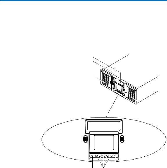
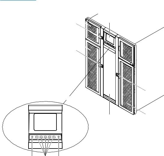
Front Panel |
Figure 1 illustrates the features of the ATL M1500 library front |
|
panel. Figure 2 illustrates the features of the ATL M2500 library |
|
front panel. |
|
These features are described in table 3. |
Figure 1 ATL M1500 |
Viewing window |
|
Front Panel |
||
GUI |
||
|
||
|
Left magazine access door |
|
Right |
|
magazine |
Operator control panel |
access door |
Left magazine |
|
Right magazine |
door button |
GUI |
door button |
|
|
Red |
GUI |
Green |
LED |
buttons |
LED |
ATL M-Series User’s Guide |
5 |
Chapter 1 Overview
Library Features
Figure 2 ATL M2500
Front Panel
Top left magazine access door (door 1) Magazine door button 
Bottom left magazine access door (door 2) Magazine door button 
Operator control panel
GUI
Red |
GUI |
Green |
LED |
buttons |
LED |
GUI
Magazine door button
Viewing window |
Right magazine |
access door |
6 |
ATL M-Series User’s Guide |

Chapter 1 Overview
Library Features
Table 3 Front Panel
Features
Feature |
Description |
|
|
|
|
Operator |
The operator control panel consists of the following elements: |
|
control panel |
• Graphical user |
The GUI displays library status information and allows |
|
||
|
interface (GUI) |
you to access the library menus. These menus allow you to |
|
|
view or change the library settings, run demonstration |
|
|
programs, or run diagnostic tests. |
|
|
The GUI is discussed in detail in this book. |
|
• Five GUI |
Use these buttons in combination with the GUI to scroll |
|
buttons |
through screens and select options or commands. The |
|
|
functionality of these buttons changes depending on the |
|
|
currently displayed GUI screen. |
|
• Magazine |
Pressing these buttons opens the magazine doors, if the |
|
door buttons |
magazines have already been released using the Mags |
|
|
option on the GUI (see Removing the Magazines on |
|
|
page 38). |
|
• Light emitting |
The operator control panel has two LED indicators: |
|
diode (LED) |
• The green LED lights when the library is fully |
|
indicators |
|
|
operational and ready to accept host commands. It |
|
|
|
|
|
|
flashes while the library is transitioning from a READY |
|
|
state to a NOT READY state. The library will not be |
|
|
READY during power-on self-tests, when magazines |
|
|
are being released, or during access to certain menu |
|
|
items. |
|
|
• The red LED lights when there is a library error. |
|
|
• Both LEDs flash when there is a library fault that |
|
|
requires operator attention. |
|
|
|
Magazine |
These doors protect the data cartridge magazines. |
|
access doors |
|
|
|
|
|
Viewing |
This window allows you to view the library robotics while the library is |
|
window |
operating. |
|
|
|
|
ATL M-Series User’s Guide |
7 |
Chapter 1 Overview
Library Features
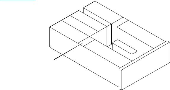
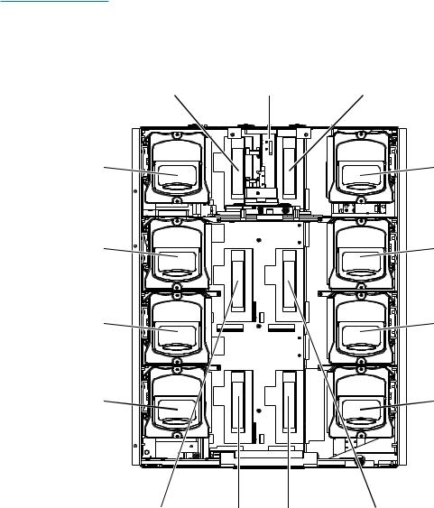
Internal Layout |
Figure 3 illustrates the internal layout of an ATL M1500 library. |
|
Figure 4 illustrates the internal layout of an ATL M2500 library. |
Figure 3 ATL M1500
Internal Layout
|
|
|
|
|
|
|
|
|
|
|
|
|
|
|
|
|
P |
|
|
|
|
|
|
|
|
|
|
|
|
|
|
|
|
|
|
|
|
|
|
|
|
|
|
|
|
|
|
|
o |
|
|
|
|
|
|
|
|
|
|
|
|
|
|
|
|
|
|
|
|
|
|
|
|
|
|
|
|
|
|
|
w |
|
|
|
|
|
|
|
|
|
|
|
|
|
|
|
|
|
|
|
|
|
|
|
|
|
|
|
|
|
|
|
e |
|
|
|
|
|
|
|
|
|
|
|
|
|
|
|
|
|
|
|
|
|
|
|
|
|
|
|
|
|
|
|
|
r |
|
|
|
|
|
|
|
|
|
|
|
|
|
|
|
|
|
|
|
|
|
|
|
|
|
|
|
|
|
|
|
s |
|
|
|
|
|
|
|
|
|
|
|
||
|
|
|
|
|
|
|
|
|
|
|
|
|
|
|
|
|
|
|
u |
|
|
|
|
|
|
|
|
|
|
|
|
|
|
|
|
|
|
|
|
|
|
|
|
|
|
|
|
|
|
|
|
p |
|
|
|
|
|
|
|
|
|
|
|
|
|
|
|
|
|
|
|
|
|
|
|
|
|
|
|
|
|
|
|
p |
|
|
|
|
|
|
|
|
|
|
|
|
|
|
|
|
|
|
|
|
|
|
T |
|
|
|
|
|
|
|
l |
|
|
|
|
|
|
|
|
|
|
|
|
|
|
|
|
|
|
|
|
|
|
|
|
|
|
|
|
|
|
y |
|
|
|
|
|
|
|
|
|
|
|||
|
|
|
|
|
|
|
|
|
|
|
|
a |
|
|
|
|
|
|
|
|
|
|
|
|
|
|
|
|
|
|
|
|
|
|
|
|
|
|
|
|
|
|
|
|
p |
|
|
|
|
|
|
|
|
|
|
|
|
|
|
|
|
|
|
|
|
|
|
|
|
T |
|
|
|
|
ed |
|
|
|
|
|
|
|
|
|
|
|
|
|
|
|
|
|
|||
|
|
|
|
|
|
|
|
|
|
|
ri |
|
|
|
|
|
|
|
|
|
|
|
|
|
|
|
|
||||
|
|
|
|
|
|
|
a |
|
|
|
|
v |
|
|
|
|
|
|
|
|
|
|
|
|
|
|
|
||||
|
|
|
|
|
|
|
|
|
p |
|
|
|
|
e |
2 |
|
|
|
|
|
|
|
|
|
|
|
|
|
|
||
|
|
|
|
|
|
|
|
|
|
|
ed |
|
|
|
|
|
|
|
|
|
|
|
|
|
|
|
|
|
|
|
|
E |
|
|
|
|
|
|
|
|
|
|
ri |
|
|
|
|
|
|
|
|
|
|
|
|
|
|
|
|
|
|
|
|
|
|
|
|
|
|
|
|
|
|
|
v |
|
|
|
|
|
|
|
|
|
|
|
|
|
|
|
|
|
|
||
l |
|
|
|
|
|
|
|
|
|
|
|
e |
|
|
|
|
|
|
|
|
|
|
|
|
|
|
|
|
|
|
|
|
e |
t |
|
|
|
|
|
|
|
|
|
1 |
|
|
|
|
|
|
|
|
|
Ri |
|
|
|
|
|
|
|
||
|
|
c |
r |
|
|
|
|
|
|
|
|
|
|
|
|
|
|
|
|
|
g |
|
|
|
|
|
|
||||
m |
|
|
o |
i |
|
|
|
|
|
|
|
|
|
|
|
|
|
|
|
h |
|
|
|
|
|
||||||
|
o |
|
|
|
n |
c |
|
|
|
|
|
|
|
|
|
|
|
|
|
|
|
t |
|
|
|
|
|||||
|
|
|
|
|
|
|
|
|
|
|
|
|
|
|
|
|
|
|
|
|
|
m |
|
|
|
||||||
|
|
d |
|
|
|
|
|
|
s |
|
|
|
|
|
|
|
|
|
|
|
|
|
|
|
|
|
|
||||
|
|
|
u |
|
|
|
|
|
|
|
|
|
|
|
|
|
|
|
|
|
|
|
|
|
|
a |
|
|
|||
|
|
|
|
|
l |
|
|
|
|
|
|
|
|
|
|
|
|
|
|
|
|
|
|
|
|
|
|
g |
|
||
|
|
|
|
|
e |
|
|
|
|
|
|
|
|
|
|
|
|
|
|
|
|
|
|
|
|
|
|
|
a |
||
|
|
|
|
|
|
|
|
|
|
|
|
|
|
|
|
|
|
|
|
|
|
|
|
|
|
|
|
|
|
|
z |
|
|
|
|
|
|
|
|
|
|
|
|
|
|
|
|
|
|
|
|
|
|
|
|
|
|
|
|
|
|
|
i |
|
|
|
|
|
|
|
|
|
|
|
|
|
|
|
|
|
|
|
|
|
|
|
|
|
|
|
|
|
|
|
n |
|
|
|
|
|
|
|
|
|
|
|
|
|
|
|
|
|
|
|
|
|
R |
|
|
|
|
|
|
|
|
e |
|
|
|
|
|
|
|
|
|
|
|
|
|
|
|
|
|
|
|
|
|
|
|
|
|
|
|
|
|
|
|
||
|
|
|
|
|
|
|
|
|
|
|
|
|
|
|
|
|
|
|
|
|
|
o |
|
|
|
|
|
|
|
|
|
|
|
|
|
|
|
|
|
|
|
|
|
|
|
|
|
|
|
|
|
|
|
b |
|
|
|
|
|
|
|
|
|
|
|
|
|
|
|
|
|
|
|
|
|
|
|
|
|
|
|
|
|
|
|
o |
|
|
|
|
|
|
|
|
|
|
|
|
|
|
|
|
|
|
|
|
|
|
|
|
|
|
|
|
|
|
|
t |
|
|
|
|
|
|
|
|
|
|
|
|
|
|
|
|
|
|
|
|
|
|
|
|
|
|
|
|
|
|
|
i |
|
|
|
|
|
|
|
|
|
|
|
|
|
|
|
|
|
|
|
|
|
|
|
|
|
|
L |
|
|
|
|
ch |
|
|
|
|
|
|
|
|
|
|
|
|
|
|
|
|
|
|
|
|
|
|
|
|
|
|
|
|
|
|
a |
|
|
|
|
|
|
|
|
||
|
|
|
|
|
|
|
|
|
|
|
|
|
|
|
|
|
e |
|
|
|
|
n |
|
|
|
|
|
|
|
||
|
|
|
|
|
|
|
|
|
|
|
|
|
|
|
|
|
|
f |
|
|
|
|
|
|
|
|
|
|
|
||
|
|
|
|
|
|
|
|
|
|
|
|
|
|
|
|
|
|
t |
|
|
|
|
d |
|
|
|
|
|
|
|
|
|
|
|
|
|
|
|
|
|
|
|
|
|
|
|
|
|
|
|
m |
|
|
|
|
|
|
|
|
|
|
|
|
|
|
|
|
|
|
|
|
|
|
|
|
|
|
|
|
|
|
|
|
a |
|
|
|
|
|
|
|
|
|
|
|
|
|
|
|
|
|
|
|
|
|
|
|
|
|
|
|
|
|
|
|
g |
|
|
|
|
|
|
|
|
|
|
|
|
|
|
|
|
|
|
|
|
|
|
|
|
|
|
|
|
|
|
|
a |
|
|
|
|
|
|
|
|
|
|
|
|
|
|
|
|
|
|
|
|
|
|
|
|
|
|
|
|
|
|
|
|
z |
|
|
|
|
|
|
|
|
|
|
|
|
|
|
|
|
|
|
|
|
|
|
|
|
|
|
|
|
|
|
|
i |
|
|
|
|
|
|
|
|
|
|
|
|
|
|
|
|
|
|
|
|
|
|
|
|
|
|
|
|
|
|
|
n |
|
|
|
|
|
|
|
|
|
|
|
|
|
|
|
|
|
|
|
|
|
|
|
|
|
|
|
|
|
|
|
e |
|
|
|
|
|
|
|
|
|
|
Fixed drive slot
8 |
ATL M-Series User’s Guide |
Chapter 1 Overview
Library Features
Figure 4 ATL M2500
Internal Layout
(Library shown with front bezel and doors removed)
Level 1 |
Robotic |
Level 1 |
tape drive 1 |
hand |
tape drive 2 |
Level 1 left |
Level 1 right |
magazine* |
magazine |
Level 2 left |
Level 2 right |
magazine* |
magazine |
Level 3 left |
Level 3 right |
magazine* |
magazine |
Level 4 left |
|
|
Level 4 right |
|
magazine* |
|
|
magazine |
|
*There is a fixed slot |
|
|
|
|
behind each left |
|
|
|
|
magazine. |
|
|
|
|
Level 2 |
Level 3 |
Level 3 |
Level 2 |
|
tape drive 1 |
tape drive 2 |
|||
tape drive 1 |
tape drive 2 |
|||
|
|
ATL M-Series User’s Guide |
9 |
Chapter 1 Overview
Library Features
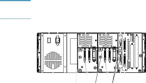
Back Panel
Figure 5 ATL M1500
Back Panel
Each cartridge magazine holds 10 DLT/SDLT cartridges or 12 LTO cartridges. The bins in the left magazines are numbered from 1 through 10 (or 12 in LTO libraries) from front to back. The bins in the right magazines are numbered from 1 through 10 (or 12 in LTO libraries) from back to front.
The ATL M1500 has one fixed cartridge slot behind the left magazine. The ATL M2500 has four fixed cartridge slots, one behind each left magazine. The fixed cartridge slots can be used as additional data cartridge bins, or can be used to hold cleaning tapes, which can be moved to a tape drive when cleaning is required.
A bar code reader is attached to the library’s robotic hand. This bar code reader automatically identifies the cartridges in the library, if the cartridges are fitted with acceptable bar code labels.
Figure 5 illustrates the back panel of the ATL M1500 library. Figure 6 illustrates the back panel of the ATL M2500 library.
|
|
|
Power inlet |
|
|
|
|
Diagnostics port |
|||||
Power switch |
|
Vent |
Vent |
|
SCSI |
||||||||
|
|
|
|
|
|
|
|
|
|
|
|
|
|
|
|
|
|
|
|
|
|
|
|
|
|
|
|
|
|
|
|
|
|
|
|
|
|
|
|
|
|
|
|
|
|
|
|
|
|
|
|
|
|
|
|
Power supply
|
|
|
|
|
|
|
|
|
|
|
|
Vent |
SCSI |
SCSI |
SCSI |
||
|
|
|
|
|
|
Electronics module
Tape drive 2 |
Tape drive 1 Interlibrary |
StackLink |
|
control |
motor drive |
10 |
ATL M-Series User’s Guide |

Figure 6 ATL M2500
Back Panel
Vents
Vent
SCSI
Vents
SCSI
Vent
Vents
SCSI
Interlibrary control
Tape |
Tape |
drive |
drive |
Tape |
Tape |
drive |
drive |
Tape |
Tape |
drive |
drive |
Chapter 1 Overview
Library Features
Diagnostics port
Electronics
module
SCSI
StackLink motor drive
Power |
inlet |
Power |
switch |
Vent
Power outlets
Power
 inlets
Power switch
Vent
ATL M-Series User’s Guide |
11 |
Chapter 1 Overview
Library Features
12 |
ATL M-Series User’s Guide |
 Loading...