


MS3580

METROLOGIC INSTRUMENTS, INC.
MS3580 QuantumT
™
Installation and User's Guide

Copyright
© 2005 by Metrologic Instruments, Inc. All rights reserved. No part of this
work may be reproduced, transmitted, or stored in any form or by any means
without prior written consent, except by reviewer, who may quote brief
passages in a review, or provided for in the Copyright Act of 1976.
Products and brand names mentioned in this document are trademarks of
their respective companies.

ii
TABLE OF CONTENTS
Introduction
Product Overview ............................................................................................. 1
Scanner and Accessories................................................................................. 2
Scanner Components....................................................................................... 4
Caution and Serial Number Labels................................................................... 5
Cable Removal.................................................................................................5
Maintenance..................................................................................................... 5
Mounting Specifications and Stand Assembly..................................................6
Installation
RS232, RS232 TTL, Light Pen or Laser Emulation .......................................... 8
IBM 46xx or OCIA ............................................................................................ 9
Keyboard Wedge............................................................................................ 10
Stand-Alone Keyboard Wedge....................................................................... 11
Full Speed or Low Speed USB (Integrated) ................................................... 12
Scanner Operation
Configurable Primary and Secondary Scan Pattern Modes ........................... 13
Configurable Button Functions ....................................................................... 13
Indicators
Audible ....................................................................................................... 19
Visual ......................................................................................................... 20
Failure ........................................................................................................ 21
Depth of Field Specifications
Normal Scan Zone ..................................................................................... 22
Reduced Scan Zone................................................................................... 23
Depth of Field by Bar Code Element Width
Normal Scan Zone ..................................................................................... 24
Reduced Scan Zone................................................................................... 25
IR Activation Range
Normal........................................................................................................ 26
Reduced..................................................................................................... 26

iii
TABLE OF CONTENTS
Troubleshooting Guide ....................................................................................... 27
Design Specifications ......................................................................................... 31
Applications and Protocols ................................................................................. 33
Default Settings - Communication Parameters................................................... 34
Upgrading the Flash ROM Firmware.................................................................. 39
Scanner and Cable Terminations ....................................................................... 40
Scanner Pinout Connections.......................................................................... 40
Cable Connector Configurations (Host End) .................................................. 42
Laser and Product Safety................................................................................... 44
Limited Warranty ................................................................................................ 46
Patents ............................................................................................................... 47
Index .................................................................................................................. 48
Contact Information and Office Locations........................................................... 50

1
INTRODUCTION
The QuantumT
™
is a hands-free, omnidirectional bar code scanner with optional
single-line scanning capabilities. It utilizes the powerful Metrologic QuantumE
™
scan engine to provide an outstanding scan performance on all standard 1D
barcode symbologies, including RSS. This fully enclosed scanner includes large
easily visible LEDs and a rugged protective boot with an adjustable stand. The
QuantumT can be mounted to a countertop, wall or be left free standing for
handheld scanning.
Key Product Features
• Fully Automatic Scanning Operation
• Single-Line Mode for Menu Reading
• Custom Configurable Scan Pattern
• User-Replaceable Single Cable Interface to Host (PowerLink Compatible)
• Decoding of All Standard 1D, RSS-14, RSS Limited and Expanded RSS
Bar Codes
• 7 Beeper Tones
• Configurable Depth of Field
• Flash - Upgradeable Firmware
• OPOS and JPOS System Compatible
• CodeGate
®
• Sunrise 2005 Compliant
QUANTUMT INTERFACE
MS3580-9 OCIA and RS232 Transmit/Receive
MS3580-11 IBM 46xx and Full RS232
MS3580-38
RS232 Low Speed USB,
Keyboard Emulation Mode or Serial Emulation Mode*
MS3580-40 Full Speed USB
MS3580-41 RS232/Light Pen Emulation
MS3580-47
Keyboard Wedge, Stand-Alone Keyboard and
RS232 Transmit/Receive
MS3580-104 RS232 TTL, Laser Emulation
* Configurable for Keyboard Emulation Mode or Serial Emulation Mode.
Default setting is Keyboard Emulation Mode.

2
INTRODUCTION
Scanner and Accessories
BASIC KIT COMPONENTS
Part No. Description
MS3580 QuantumT Omni \ Single-Line Scanner
00-02026
QuantumT Omni \ Single-Line Scanner
Installation and User’s Guide *
00-02407 MetroSelect
®
Configuration Guide *
* Guides also available for download at www.metrologic.com.
OPTIONAL ACCESSORIES
Part No. Description
AC to DC Power Transformer - Regulated 5.2VDC @ 650 mA output.
45-45593 120V United States and Canada
45-45591 220V-240V Continental European
45-45592 220V-240V United Kingdom
46-46803 220V-240V Australia
46-46983 220V-240V China
54-54000x -3
RS232 PowerLink Cable with Built in Power Jack
2.1 m (7 ft.) straight cord, short strain relief
MVC** Metrologic Voltage Converter Cable ±12VDC to +5.2VDC
** Contact a Metrologic customer service representative for additional
information on the MVC cable series and the host connections available.
Other items may be ordered for the specific protocol being used. To order additional items,
contact the dealer, distributor or call Metrologic’s customer service department at
1-800-436-3876
.
3
INTRODUCTION
Scanner and Accessories
OPTIONAL ACCESSORIES
Part No. Description
54-54002x-3
Keyboard Wedge PowerLink Cable
2.1 m (7 ft.) straight cord, short strain relief
54-54020x-3
Stand Alone Keyboard PowerLink Cable
2.1 m (7 ft.) straight cord, short strain relief
54-54213x-N-3
USB Full Speed Cable, Locking Plus-Power
™
Type A
3 m (10 ft.) straight cord, short strain relief
54-54214x-N-3
USB Full Speed Cable, Locking Plus-Power
™
Type A
5 m (17 ft.) straight cord, short strain relief
This cable is for use with full speed
USB (-40) interface only.
54-54235x-N-3
USB Low Speed Communication Cable, Type A
2.8 m (9.2 ft.) straight cord, short strain relief
54-54249x-N-3
Communication Cable, Host End Not Terminated
203 mm (8") straight cord, short strain relief
46-00288 Flex Stand (3")
46-00289 Flex Stand (6")
Other items may be ordered for the specific protocol being used. To order additional items,
contact the dealer, distributor or call Metrologic’s customer service department at
1-800-436-3876.
4
INTRODUCTION
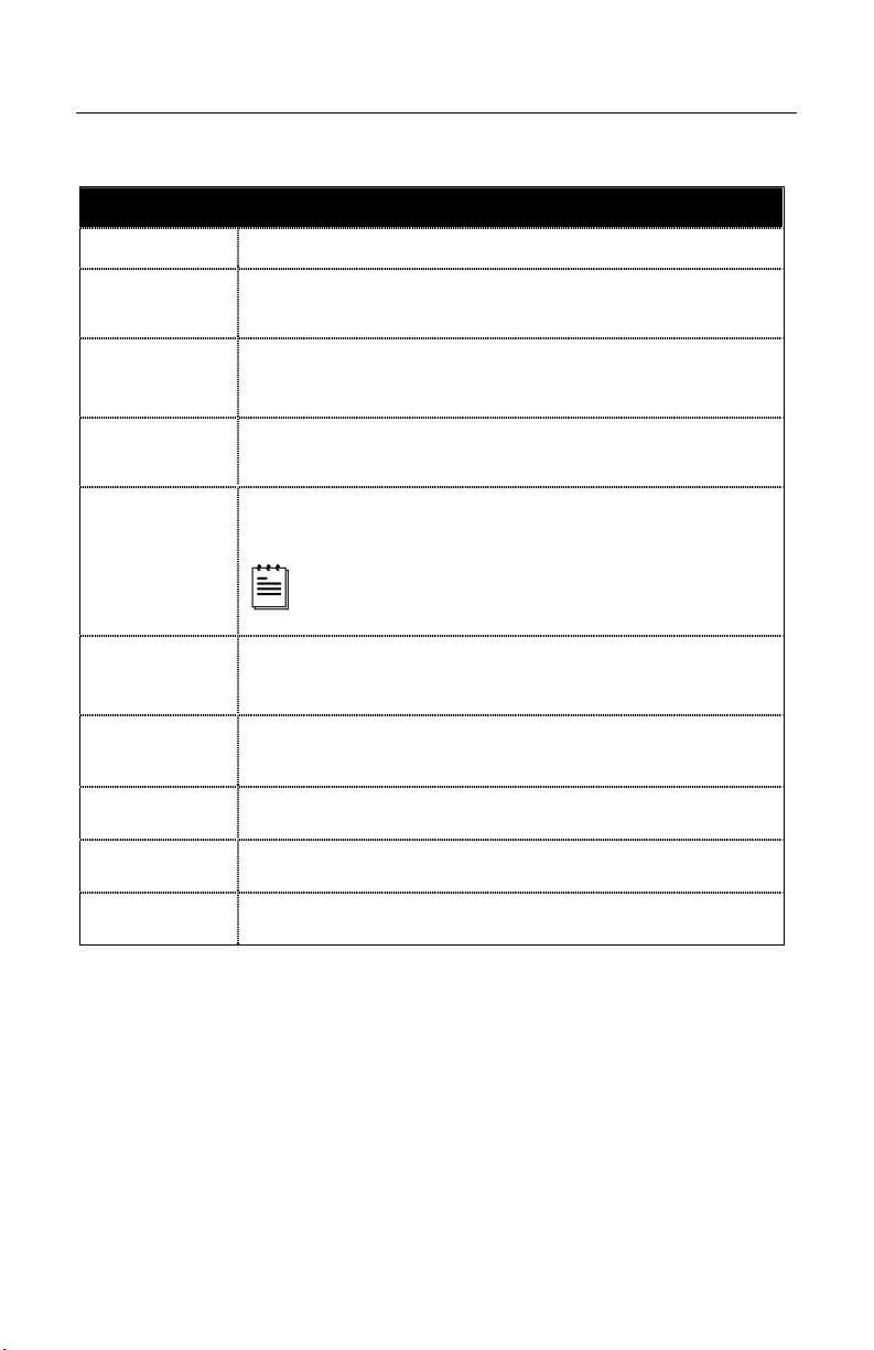
Scanner Components
Figure 1. Scanner Components
ITEM NO.
DESCRIPTION
1 Red Output Window (Laser Aperture)
2 Pin Hole for Cable Release
3 10-Pin RJ45, Female Socket
4 Speaker
5 Blue and White LED Indicators
6 Button
7
Protective Boot and Stand Connection
Never remove the protective boot from the MS3580.
Removing the protective boot will expose electrical
components of the scanner that are highly susceptible to
e
lectrostatic discharge (ESD).
8
Pedestal Stand
The type of stand provided is dependent on the specific
MS3540 kit purchased.
5
INTRODUCTION
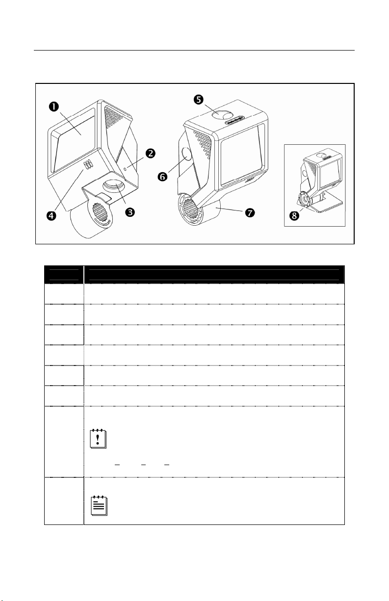
Caution and Serial Number Labels
Figure 2.
Cable Removal
1. Locate the small ‘pin-hole’ on the side of
the QuantumT near the cable.
2. Bend an ordinary paperclip into the shape
shown.
3. Insert the paperclip (or other small metallic
pin) into the small ‘pin-hole’.
4. You will hear a faint ‘click’ when the cable
lock is released. Pull gently on the strain-
relief of the PowerLink cable to remove it
from the scanner.
Figure 3.
Maintenance
Smudges and dirt can interfere with the proper scanning of a bar code.
Therefore, the output window will need occasional cleaning.
1. Spray glass cleaner onto a lint free, non-abrasive cleaning cloth.
2. Gently wipe the scanner window.
6
INTRODUCTION
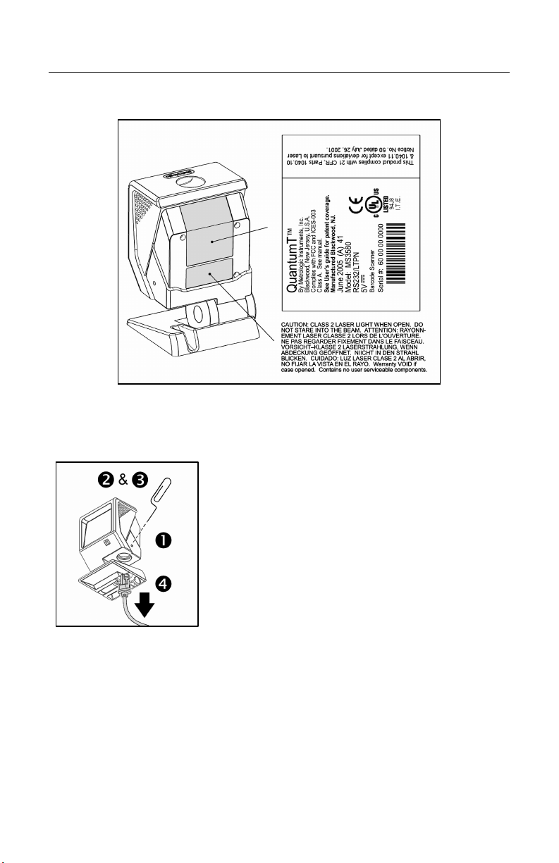
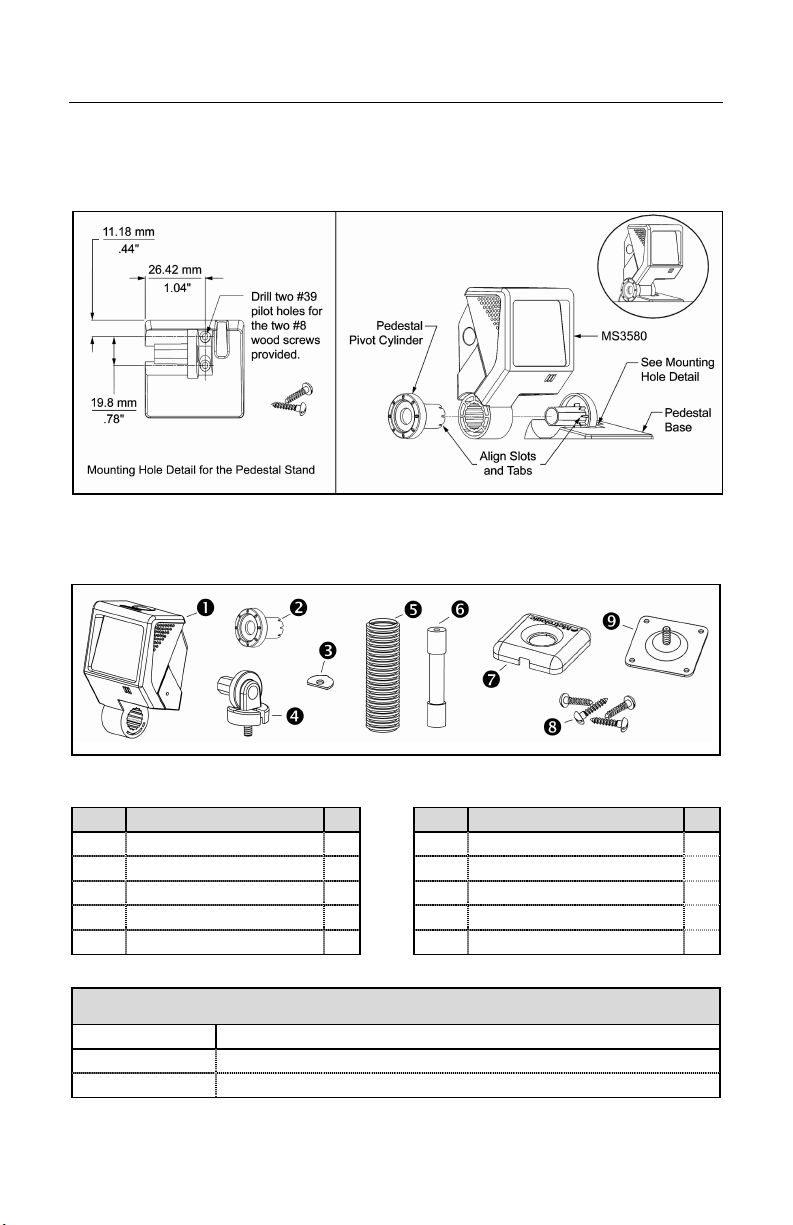
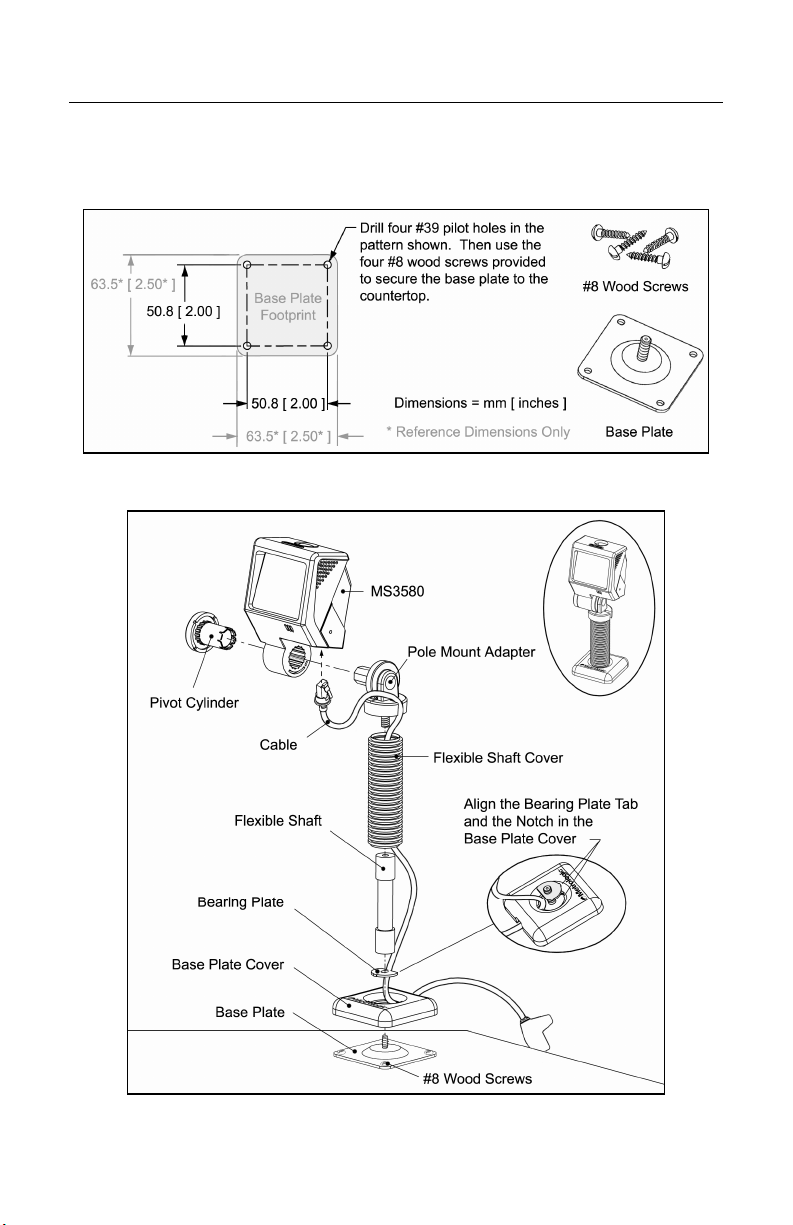
Mounting Specifications and Stand Assembly
Pedestal Stand
Figure 4. Pedestal Stand Assembly
Optional Flex Stand
Figure 5. Assembly Components for Optional Flex Stand
Item Description Qty. Item Description Qty
1 MS3580, QuantumT 1 6 Flexible Shaft* 1
2 Pivot Cylinder 1 7 Base Plate Cover 1
3 Bearing Plate 1 8 #8 x 1.00" Wood Screw 4
4 Pole Mount Adapter 1 9 Base Plate 1
5 Flexible Shaft Cover* 1
10 Cable (Not Shown) 1
* Length of the Flexible Shaft and Shaft Cover are Kit Dependent
Kit Number Length of Flexible Shaft and Flexible Shaft Cover
46-00288 3 inches
46-00289 6 inches
7
INTRODUCTION
Mounting Specifications and Stand Assembly
Optional Flex Stand
Figure 6. Mounting Hole Detail for the Flex Stand Base Plate (Optional)
Figure 7. Assembling the Optional Flex Stand
8
INSTALLATION
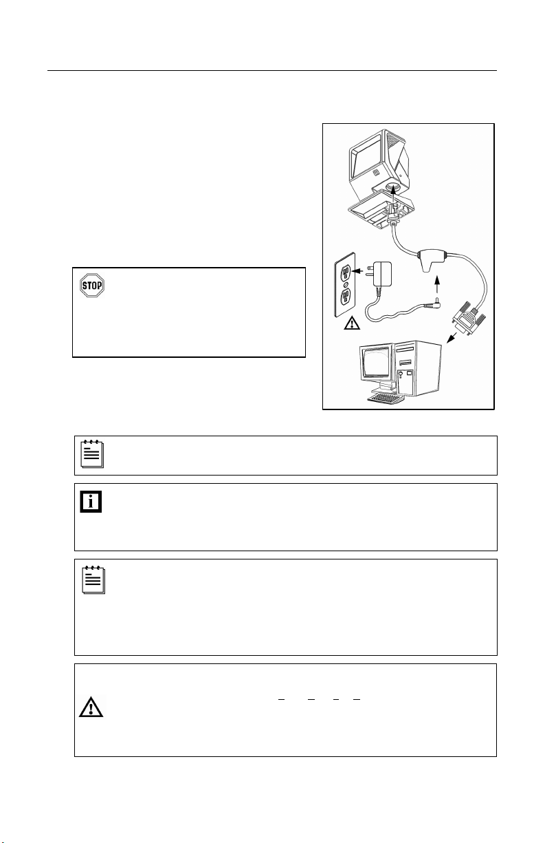
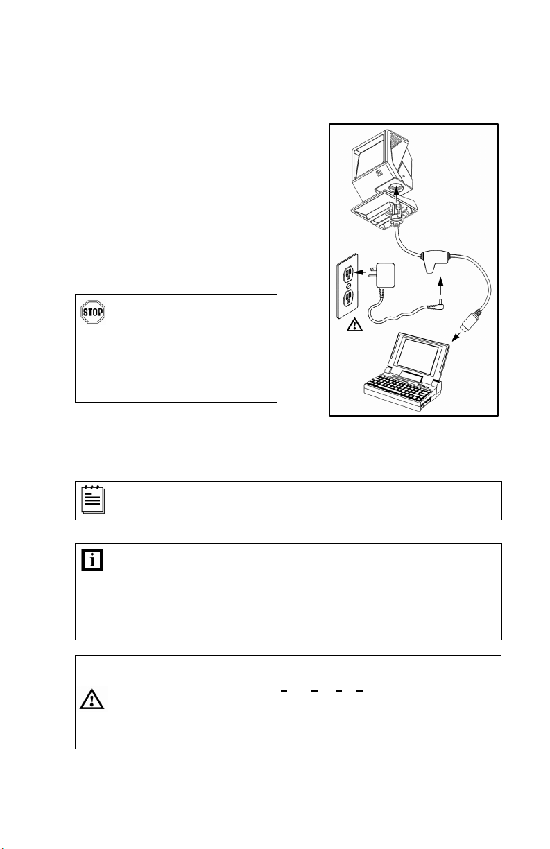
RS232, RS232 TTL, Light Pen or Laser Emulation
1. Turn off the host device.
2. Plug the male 10-pin RJ45 end
of the PowerLink cable into the
10-pin socket on the MS3580.
3. Connect the 9-pin female end of the
PowerLink cable to the host device.
4. Plug the external power supply into the
power jack on the PowerLink cable.
Check the AC input requirements
of the power supply to make sure
the voltage matches the AC outlet.
The outlet must be located near
the equipment and be easily
accessible.
5. Connect AC power to the transformer.
6. Turn on the host device.
When the scanner first receives power, the blue LED will turn on; the
scanner will simultaneously emit a beep and flash the white LED.
Plugging the scanner into the serial port of the PC does not guarantee
that scanned information will appear at the PC. A software driver and
correct configuration setting are also required for proper
communication to occur.
The MS3580-104 leaves the factory with the Laser Emulation
enabled. If the Recall Defaults bar code is scanned while
reconfiguring the scanner, laser emulation will no longer be enabled.
Scan the Laser Emulation barcode in Section J: Laser Emulation of
the MetroSelect Configuration Guide to re-enable the laser emulation
interface. This feature is only supported for MS3580-104 models.
Caution
To maintain compliance with applicable standards, all circuits connected to the scanner
must meet the requirements for SELV (Safety Extra Low Voltage) according to EN/IEC
60950.
To maintain compliance with standard CSA C22.2 No. 60950/UL 60950 and norm
EN/IEC 60950, the power source should meet applicable performance requirements for
a limited power source.
Figure 8.
9
INSTALLATION
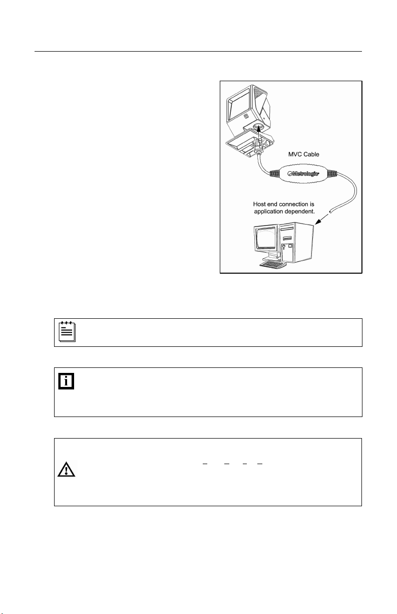
IBM 46xx or OCIA
1. Turn off the host device.
2. Plug the male 10-pin RJ45 end
of the MVC cable into the
10-pin socket on the MS3580.
3. Connect the other end of the MVC
cable to the host device.
4. Turn on the host device.
When the scanner first receives power, the blue LED will turn on; the
scanner will simultaneously emit a beep and flash the white LED.
Plugging the scanner into the serial port of the PC does not
guarantee that scanned information will appear at the PC. A software
driver and correct configuration setting are also required for proper
communication to occur.
Caution:
To maintain compliance with applicable standards, all circuits connected to the scanner
must meet the requirements for SELV (Safety Extra Low Voltage) according to EN/IEC
60950.
To maintain compliance with standard CSA C22.2 No. 60950/UL 60950 and norm
EN/IEC 60950, the power source should meet applicable performance requirements for
a limited power source.
Figure 9.
10
INSTALLATION
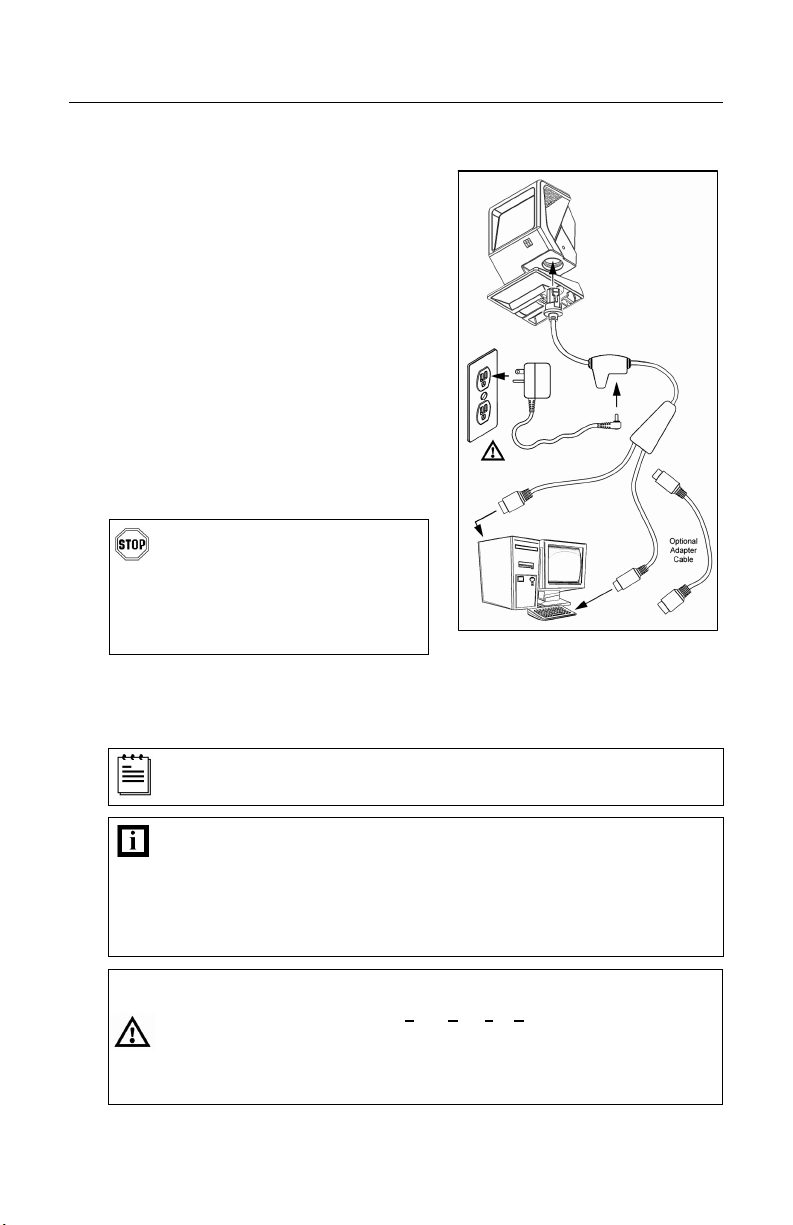
Keyboard Wedge
1. Turn off the host device.
2. Plug the male 10-pin RJ45 end of the
PowerLink cable into the 10-pin
socket on the MS3580.
3. Disconnect the keyboard from the
host device.
4. Connect the “Y” end of the PowerLink
cable to the keyboard and the
keyboard port on the host PC. If
necessary use the male/female
adapter cable supplied with the
scanner for proper connections.
5. Plug the external power supply into the
power jack on the PowerLink cable.
Check the AC input requirements
of the power supply to make sure
the voltage matches the AC
outlet. The outlet must be
located near the equipment and
be easily accessible.
6. Connect AC power to the transformer.
7. Turn on the host device.
When the scanner first receives power, the blue LED will turn on; the
scanner will simultaneously emit a beep and flash the white LED.
Powering the MS3580 directly from the host device can sometimes
cause interference with the operation of the scanner or the computer.
Not all computers supply the same current through the keyboard port.
For this reason, Metrologic recommends using an external power
supply. For additional information contact a Metrologic customer
service representative.
Caution:
To maintain compliance with applicable standards, all circuits connected to the scanner
must meet the requirements for SELV (Safety Extra Low Voltage) according to EN/IEC
60950.
To maintain compliance with standard CSA C22.2 No. 60950/UL 60950 and norm
EN/IEC 60950, the power source should meet applicable performance requirements for
a limited power source.
Figure 10.
11
INSTALLATION
Stand-Alone Keyboard
1. Turn off the host device.
2. Plug the male 10-pin RJ45 end
of the PowerLink cable into the
10-pin socket on the MS3580.
3. Connect the other end of the
PowerLink cable to the keyboard
port on the host device.
4. Plug the external power supply into
the power jack on the PowerLink
cable.
Check the AC input
requirements of the power
supply to make sure the
voltage matches the AC
outlet. The outlet must be
located near the equipment
and be easily accessible.
5. Connect AC power to the transformer.
6. Turn on the host device.
When the scanner first receives power, the blue LED will turn on; the
scanner will simultaneously emit a beep and flash the white LED.
Powering the MS3580 directly from the host device can sometimes
cause interference with the operation of the scanner or the computer.
Not all computers supply the same current through the keyboard port.
For this reason, Metrologic recommends using an external power
supply. For additional information contact a Metrologic customer
service representative.
Caution:
To maintain compliance with applicable standards, all circuits connected to the scanner
must meet the requirements for SELV (Safety Extra Low Voltage) according to EN/IEC
60950.
To maintain compliance with standard CSA C22.2 No. 60950/UL 60950 and norm
EN/IEC 60950, the power source should meet applicable performance requirements for
a limited power source.
Figure 11.
12
INSTALLATION
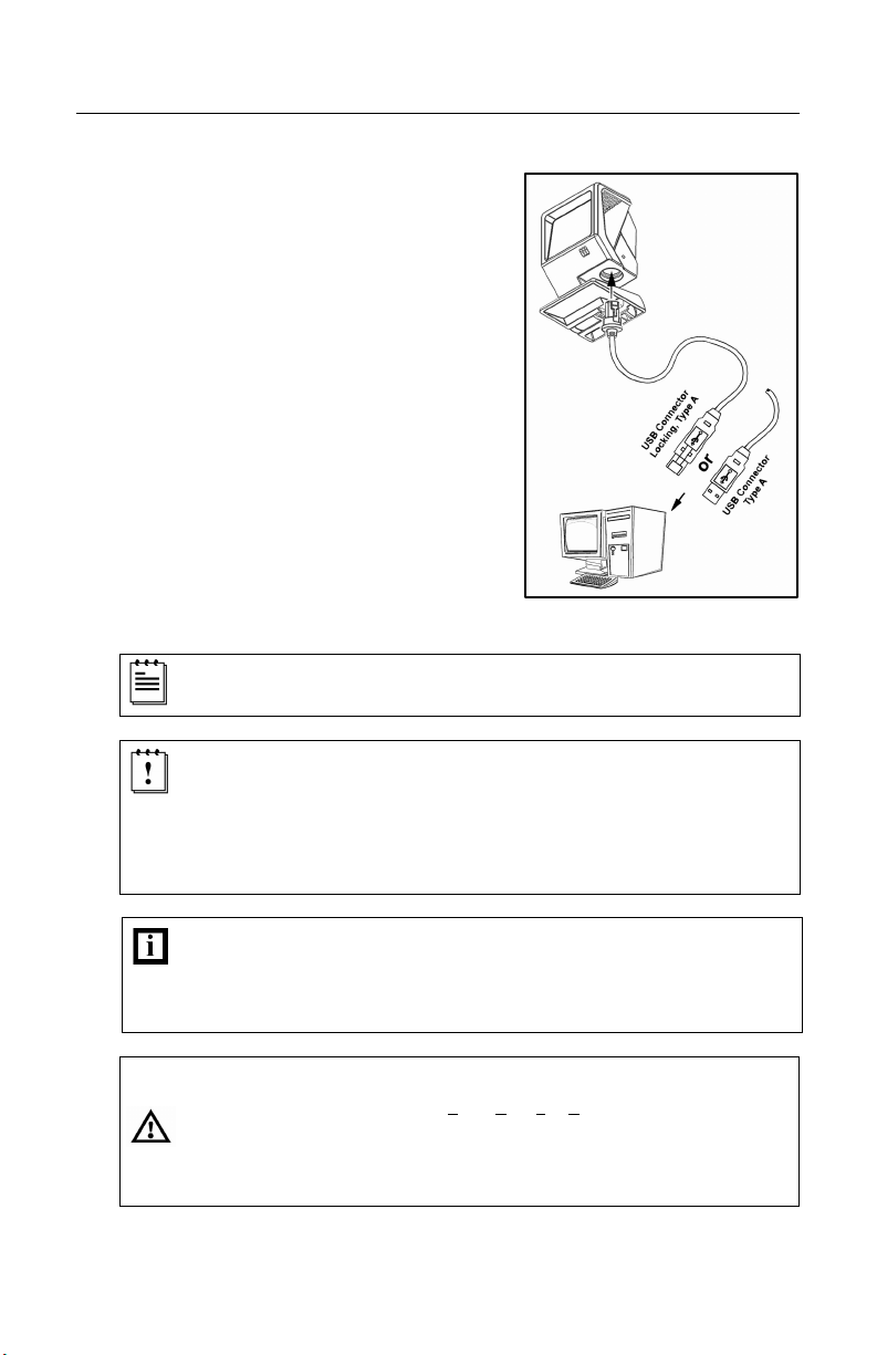
Full Speed or Low Speed USB
1. Turn off the host device.
2. Plug the male 10-pin RJ45 end of
the USB cable into the 10-pin
socket on the MS3580.
3. Plug the other end of the USB
interface cable into the host
device’s USB port.
4. Turn on the host device.
When the scanner first receives power, the blue LED will turn on; the
scanner will simultaneously emit a beep and flash the white LED.
As a default, the MS3580-38 leaves the factory with USB Keyboard
Emulation Mode enabled.
For information on configuring the MS3580-38 for USB Serial
Emulation Mode, please refer to Section P: Low Speed USB in the
MetroSelect Configuration Guide (MLPN 00-02407).
Plugging the scanner into the USB port of the PC does not guarantee
that scanned information will appear at the PC. A software driver and
correct configuration setting are also required for proper
communication to occur.
Caution:
To maintain compliance with applicable standards, all circuits connected to the scanner
must meet the requirements for SELV (Safety Extra Low Voltage) according to EN/IEC
60950.
To maintain compliance with standard CSA C22.2 No. 60950/UL 60950 and norm
EN/IEC 60950, the power source should meet applicable performance requirements for
a limited power source.
Figure 12.
13
SCANNER OPERATION
Configurable Primary and Secondary Scan Pattern Modes
There are two configurable scan pattern modes available with the MS3580.
• The primary scan pattern mode is the default scan pattern active when the
scanner starts.
• The secondary scan pattern mode is activated by pressing the button
located on the side of the scanner. This mode is also referred to as the
button mode. For additional information on Quantum’s button modes and an
example of each, please refer to Configurable Button Functions below.
The scanner returns to the primary scan pattern mode after a double
click of the button or if the unit has not scanned a bar code for the
duration of a pre-configured time limit.
Each pattern mode can be configured to use one of three scan patterns listed
below. Please refer to the MetroSelect Configuration Guide for information on
changing the default scan pattern settings.
• all scan lines on (omnidirectional reading)
• single-line (menu reading)
• horizontal raster
If CodeGate is enabled, it will apply to the secondary pattern mode
when scanning. For detailed information on CodeGate and the button
refer to the Configurable Button Functions.
Configurable Button Functions
The button on the side of the MS3580 can be configured to function in one of
four modes.
• Button Click Mode, with CodeGate Enabled (Default)
• Button Click Mode, with CodeGate Disabled
• Button Hold Mode, with CodeGate Enabled
• Button Hold Mode, with CodeGate Disabled
The following pages include examples of how the button will function when the
unit has been configured to operate in each of the four button modes.
 Loading...