


R
SAPPHIRE
DIRECT VENT ROOM HEATER
Owner’s Manual
Installation and Operation
Model:
|
839-1390 |
|
|
|
839-1440 |
|
|
|
839-1460 |
Solitaire Front |
|
Quartet Front |
SAPPH-D-CSB |
||
|
|||
SAPPH-D-CWL |
|
||
|
Tested and |
Beaverton |
|
|
Listed by |
Oregon USA |
|
|
C |
US |
OMNITest Laboratories, Inc.
CAUTION
DO NOT DISCARD THIS MANUAL
• Important operating and • |
Read, understand and |
• Leave this manual with |
maintenance instructions |
follow these instructions |
party responsible for use |
included. |
for safe installation and |
and operation. |
|
operation. |
|
DO DISCARDNOT
WARNING: If the information in these instructions is not followed exactly, a fire or explosion may result causing property damage, personal injury, or death.
•Do not store or use gasoline or other flammable vapors and liquids in the vicinity of this or any other appliance.
•What to do if you smell gas
-Do not try to light any appliance. Do not touch any electrical switch. Do not use any phone in your building.
-Immediately call your gas supplier from a neighbor’s phone. Follow the gas supplier’s instructions.
-If you cannot reach your gas supplier, call the fire department.
•Installation and service must be performed by a qualified installer, service agency, or the gas supplier.
Installation and service of this appliance should be performed by qualified personnel. Hearth & Home Technologies suggests NFI certified or factory-trained professionals, or technicians super-
vised by an NFI certified professional.
 WARNING
HOT! DO NOT TOUCH. SEVERE BURNS MAY RESULT.
CLOTHING IGNITION MAY RESULT.
Glass and other surfaces are hot during operation and cool down.
•Keep children away.
•CAREFULLY SUPERVISE children in same room as appliance.
•Alert children and adults to hazards of high temperatures.
•Do NOT operate with protective barriers open or removed.
•Keep clothing, furniture, draperies and other combustibles away.
In the Commonwealth of Massachusetts:
•installation must be performed by a licensed plumber or gas fitter.
See Table of Contents for additional Commonwealth of Massachusetts requirements.
This appliance may be installed as an OEM installation in manufactured home (USA only) or mobile home and must be installed in accordance with the manufacturer's instructions and the manufactured home construction and safety standard, Title 24 CFR, Part 3280 or Standard for Installation in Mobile Homes, CAN/CSA Z240MH.
This appliance is only for use with the type(s) of gas indicated on the rating plate.
www.quadrafire.com |
250-7233F |
January 28, 2008 |
Hearth & Home Technologies welcomes you to our tradition of excellence! In choosing a Quadra-Fire appliance, you have our assurance of commitment to quality, durability, and performance.
This commitment begins with our research of the market, including ‘Voice of the Customer’ contacts, ensuring we make products that will satisfy your needs. Our Research and Development facility then employs the world’s most advanced technology to achieve the optimum operation of our stoves, inserts and fireplaces. And yet we are old-fash- ioned when it comes to craftsmanship. Each appliance is
meticulously fabricated and gold and nickel surfaces are hand-finished for lasting beauty and enjoyment. Our pledge to quality is completed as each model undergoes a quality control inspection. From design, to fabrication, to shipping: Our guarantee of quality is more than a word, it’s QuadraFire tradition, and we proudly back this tradition with a Limited Lifetime Warranty.
We wish you and your family many years of enjoyment in the warmth and comfort of your hearth appliance. Thank you for choosing Quadra-Fire.
With warm regards,
___________________________ |
___________________________ |
_________________________ |
___________________________ |
|
Alan Trusler |
Dan Henry |
|||
Jason Olmstead |
Steve Tate |
|||
Vice President |
Vice President |
Vice President & |
||
Quadra-Fire |
||||
Dealer Channel |
Advanced Technolgies |
General Manager |
||
Brand Manager |
||||
|
|
|
SAMPLE OF SERIAL NUMBER / SAFETY LABEL
LOCATION: ON BACK OF APPLIANCE
|
|
|
|
|
|
|
|
|
|
SERIAL NO. |
|
|
|
|
|
|
|
MODEL / MODÈLE: SAPPHIRE |
|
|
|
|
|
|
|
||
|
|
|
|
|
|
007 |
|
|
|
|
|||
|
|
|
|
VENTED GAS FIREPLACE HEATER |
|
|
|
|
|
|
|||
|
|
|
|
|
|
|
|
|
1445 North HIghway |
|
|||
|
|
|
|
FOURNAISE AU GAZ AVEC VENTILATION |
|
|
|
|
|||||
|
Report No. / Rapport Numéro |
NOT FOR USE WITH SOLID FUEL/ |
|
|
|
|
|
Colville, WA 99114 |
|
||||
|
|
061-S-19b-5 |
|
NE PAS UTILISER AVEC LE COMBUSTIBLE |
|
|
|
www.quadrafire.com |
|
||||
|
|
|
|
|
SOLIDE |
|
|
|
|
|
|
|
|
|
APPROVED FOR CANADA AND USA TO: |
|
|
|
|
APPROUVÉ POUR LE CANADA ET LES ÉTATS-UNIS: |
|
||||||
|
ANSI Z21.88A-2000 / CSA 2.33a-M00 Vented Gas Fireplace Heaters, and |
|
|
ANSI Z21.88a-2000/ CSA 2.33a-M00 Fournaisesau Gaz avec Ventilation, |
|
||||||||
|
applicable sections of UL307b Gas Burning Heating Appliances for Manufactured |
|
|
et les sectionsapplicablede UL 307b Appareils de Chauffage Au Gaz pour |
|
||||||||
|
Homes and RecreationalVehicles,CAN/CGA 2.17-M91 “Gas Fired Appliances |
|
|
les Maisons Mobiles et les Véhicules Motorisés, CAN/CGA 2.17-M91 “Gas |
|
||||||||
|
for use at High Altitudes.” This appliance is manufactured for operation with |
|
|
Fired Appliances for use at High Altitudes”. Cet appareil est manufacturé |
|
||||||||
|
Natural Gas. |
|
|
|
|
|
|
pour l’opération avec le Gaz Naturel. Pour une conversionau gaz propane |
|
||||
|
For conversion to propane Manufacturer’s Part #844-9730 and instructions must |
|
|
les pièces du Manufacturier #844-9730 et ses instructions doivent être |
|
||||||||
|
be used. This appliance may be installed in a bedroom or bedsitting room; in |
|
|
utilisées. Cet appareilpeut être utilisé dans une chambreà coucherou salle |
|
||||||||
|
Canada remote thermostat installation is required. |
|
|
|
de séjour; au Canada, l’installation d’un thermostat à distance est exigée. |
|
|||||||
|
FAN TYPE VENTED CIRCULATOR / VENTILATEUR |
Thermal E fficiency / E fficacité Thermique * |
|
|
|
||||||||
|
|
|
CIRCULATOIRE |
|
|
|
|
|
|
84% NG (blower on / avec ventilateur allumé) |
|
||
|
Blower Electrical Rating / Évaluation du Ventilateur |
|
|
|
|
|
82% LP (blower on / avec ventilateur allumé) |
|
|||||
|
|
|
|
|
|
|
|
|
|||||
|
|
|
Électrique: |
|
|
|
|
* With Maximum horizontal length. / Avec longueur horizontale maximum. |
|
||||
|
|
115 V., 1.5 Amps, 60 Hz, 150 Watts |
P.4.1-02 Canada Minimum pipe (P.4.1-02 Le canada tuyau minimum) 64.08% NG / 65.42% LP |
|
|||||||||
|
|
|
|
|
|
|
|
|
|
|
|
||
|
|
|
|
For use with Natural Gas |
For use with Propane |
|
|
|
|
||||
|
|
|
|
Usage au Gaz Naturel |
Usage au Gaz Propane |
|
|
|
|
||||
Top Vent: Input Rate on “HI” (BTU/Hr) |
|
0-2000’ |
0-2000’ |
Bouche Supérieure: |
Puissance Évaluée à “HI” (BTU/Hr) |
|
|||||||
|
30,000 |
30,000 |
|
||||||||||
|
|
Input Rate on “LO” (BTU/Hr) |
|
21,000 |
24,500 |
|
Puissance Évaluée à “LO” (BTU/Hr) |
|
|||||
|
|
Maximum Output (BTU/Hr) |
|
25,000 |
24,600 |
|
Puissance Maximum (BTU/Hr)** |
|
|||||
|
|
Main Burner Orifice |
|
.1065 (36DMS) |
.0635 (52DMS) |
|
Orifice du Brûleur Principal |
|
|||||
Rear Vent: (No vertical) Input Rate on “HI” (BTU/Hr) |
26,000 |
26,000 |
Conduit postérieur: |
Puissance Évaluée (non vertical) à “HI” (BTU/Hr) |
|
||||||||
|
|
Input Rate on “LO” (BTU/Hr) |
|
18,000 |
20,000 |
|
Puissance Évaluée à “LO” (BTU/Hr) |
|
|||||
|
|
Main Burner Orifice |
|
.0960 (41DMS) |
.0595 (53DMS) |
|
Orifice du Brûleur Principal |
|
|||||
Minimum Inlet Pressure (Inches W.C.) |
|
4.5” |
|
11” |
Pression Minimum de la Valve (pouces W.C.) |
|
|||||||
Maximum Inlet Pressure (Inches W.C.) |
|
7.0” |
|
14” |
Pression Maximum de la Valve (pouces W.C.) |
|
|||||||
Manifold Pressure on “HI” (Inches W.C.) |
|
3.5” |
|
10” |
Pression du Collecteur d’ Échappement à “HI” (pouces W.C.) |
|
|||||||
**Max. Venting, Blower On |
|
|
|
|
|
|
|
** Ventilation Maximum, Ventilateur Allumé |
|
||||
|
|
|
|
|
|
|
|
|
|
||||
CAUTION: DO NO T OPERATE |
THIS APPLIANCE WITH GLASS REMOVED, CRACKED |
OR BROKEN. REPLACEMEN T OF THE PANEL(S) |
SHOULD BE DONE BY A LICENSED OR QUALIFIED |
|
|||||||||
SE RVICE PERSON . |
|
|
|
|
|
|
|
|
|
|
|
||
ATTENTION: |
CE T APPAREIL |
NE DOI T PAS ÊTRE OPÉRÉ |
SI LA VITRE ES T BRISÉE, |
CRAQUÉE |
OU ENLEVÉE. LE REMPLACEMEN T DU PANNEAU DOI T ÊTRE FAI T PAR UNE PERSONNE |
|
|||||||
LICENSÉE E |
T QUALIFIÉE . |
|
|
|
|
|
|
|
|
|
|
|
|
CAUTION: HOT WHILE IN OPERATION. DO NOT TOUCH. SEVERE BURNS MAY RESULT. KEEP CHILDREN, CLOTHING, FURNITURE, GASOLINE AND OTHER LIQUIDS HAVING FLAMMABLE VAPORS AWAY.
ATTENTION: CHAUD LORQU’IL EST EN OPÉRATION. NE TOUCHEZ PAS. DES BRÛLURES SÉVÈRES PEUVENT EN RÉSULTER. GARDEZ LES ENFANTS, LES VÊTEMENTS, LES MEUBLES, LA GAZOLINE ET LES AUTRES LIQUIDES DE VAPEUR INFLAMMABLE ÊLOIGNÉ S
WARNING : IMPROPE R INSTALLATION , ADJUSTMEN T, ALTERATION , SERVIC E OR MAINTENANC E CA N CAUS E INJUR Y OR PROPE RTY DAMAGE . REFE R TO THE OWNER’ S INFORMATIO N
MANUAL PROVIDED WITH THIS APPLIANCE. FOR ASSISTANCE OR ADDITIONAL INFORMATION CONSUL |
T A QUALIFIED INSTALLER, SERVICE AGENCY OR THE GAS SUPPLIER |
. |
|||
AVE RTISSEMEN T: UNE INSTALLATION, UN AJUSTEMEN |
T, UNE ALTÉRATION, |
UN SERVICE OU UN ENTRETIEN INCORRECTS PEUVEN T CAUSER |
DES DOMMAGES MATÉRIELS. |
||
RÉFÉREZ-VOUS AU MANUEL D’INFORMATION FOURNI |
AVEC CE T APPAREIL. |
POUR ASSISTANCE |
OU DES INFORMATIONS SUPPLÉMENTAIRES |
CONSULTEZ UN INSTALLATEUR |
|
QUALIFIÉ, UNE AGENCE DE SERVICE OU UN FOURNISSEUR DE GAZ.
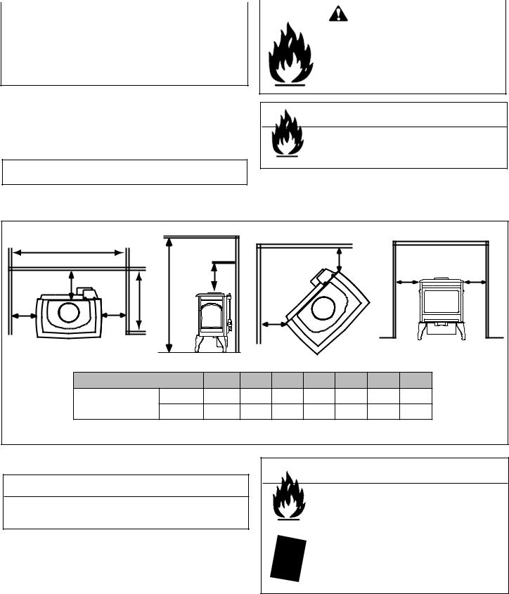
MINIMUM CLEARANCES TO COMBUSTIBLES / ESPACE MINIMUM AUX COMBUSTIBLES
Minimum clearances required from combustible construction for all appliance surfaces. / Espaces minimum exigés de la construction combustible aux surfaces de l’appareil. 

|
F |
C |
|
|
|
|
G |
|
|
|
|
D |
A |
A |
|
|
|
|
|
|
B |
|
|
|
|
E |
C |
|
|
A |
A |
|
|
|
|
|
|
||
A. |
Side of stove top to side wall |
6 in. (152 mm) |
|
Du coté du poêle au coté du mur |
B. |
Rear of stove top to back wall |
3 in. (76 mm) |
Le contrôle arrière au mur arrière |
|
C. |
Corner of stove top to side wall |
1 in. (25 mm) |
Du Coin du Poêle au coté du mur |
|
D. |
Minimum Alcove Height |
54 in. (1372 mm) |
Hauteur minimum de l'alcôve |
|
E. |
Maximum Alcove Depth |
36 in. (914 mm) |
Profondeur maximum de l'alcôve |
F. |
Minimum Alcove Width |
36 in. (914 mm) |
Largeur minimum de l'alcôve |
G. |
Mantle Clearance from stove top |
23 in. (584 mm) |
Espace libre du poéle au manteau |
HEA RTH: A non-combustible hearth pad is not required. However, the floor beneath the stove must be stable, level, and strong enough to support the stove without a tipping hazard |
. |
|
||||||||
CHEMINÉE: Un coussinet non-combustible |
de cheminée n’est pas exigé. Cependant, |
le plancher en dessous du poêle doit être droit, à niveau et assez fort pour supporter le poêle |
|
|||||||
sans le hasard de basculer. |
|
|
|
|
|
|
|
|
|
|
|
|
Date of Manufacture / Date du Manufacturier |
|
|
|
|
||||
|
2005 2006 2007 |
Jan Feb Mar |
Apr |
May Jun |
Jul |
Aug Sep Oct Nov |
Dec |
|
|
|
|
DO NOT REMOVE THIS LABEL / NE PAS ENLEVER L’ÉTIQUETT |
Made in U.S.A. / Fait Aux États-Unis |
250-7241 |
|
||||||
|
|
|||||||||
Serial Number
Barcode
Model Name
Test Lab & Report No.
Manufactured Date
Page 2 |
Quadra-Fire · Sapphire · 250-7233F |
January 28, 2008 |

- TABLE OF CONTENTS -
Section 1: Listing and Code Approvals |
|
|
A. |
Appliance Certifications ...................... |
4 |
B. |
Glass Specifications............................ |
4 |
C. |
BTU Specifications.............................. |
4 |
D. |
High Altitude Installations.................... |
4 |
E. |
Non-Combustible Materials................. |
4 |
F. |
Combustible Materials ........................ |
4 |
G. |
Requirements for the |
|
|
Commonwealth of Massachusetts ...... |
5 |
Section 2: Getting Started |
|
|
A. |
Design & Installation |
|
|
Considerations.................................... |
6 |
B. |
Tools and Supplies Needed................ |
6 |
C. |
Inspect Appliance & Components....... |
6 |
Section 3: Appliance Location & Clearances |
|
|
A. |
Selecting Appliance Location.............. |
7 |
B. |
Clearances to Combustibles............... |
7 |
Section 4: Termination Locations |
|
|
A. |
Vent Termination Minimum |
|
|
Clearances.......................................... |
8 |
Section 5: Vent Information |
|
|
A. |
Venting Components .......................... |
10 |
B. |
Use of Elbows..................................... |
10 |
C. |
Measuring Standards.......................... |
10 |
D. |
How to Use the Vent Graph ................ |
11 |
E. |
Venting Guidelines.............................. |
11 |
F. |
Horizontal Termination........................ |
12 |
G. |
Vertical Termination ............................ |
15 |
Section 6: Gas Information |
|
|
A. |
Fuel Conversions................................ |
23 |
B. |
Gas Pressures.................................... |
25 |
C. |
Gas Connection.. ................................25 |
|
Section 7: Electrical Information |
|
|
A. |
Recommendation for Wire .................. |
27 |
B. |
Connecting to the Appliance ............... |
27 |
C. |
Standing Pilot Ignition |
|
|
System Wiring ..................................... |
27 |
Section 8: Appliance Setup |
|
|
A. |
Remove Shipping Materials ................ |
29 |
B. |
Top to Rear Vent Conversion ............. |
29 |
C. |
Grille Cover Installation....................... |
31 |
D. |
Accessories......................................... |
31 |
E. |
Front Installation ................................. |
32 |
F. |
Hearth Legs Installation ...................... |
33 |
G. |
Positioning the Logs............................ |
33 |
H. |
Mineral Wool ....................................... |
34 |
I. |
Glass Door Assembly ......................... |
34 |
J. |
Blower Installation............................... |
34 |
K. |
Damper Adjustment ............................ |
37 |
L. |
Shutter Adjustment ............................. |
37 |
Section 9: Operating Instructions |
|
|
A. |
Before Lighting Appliance ................... |
38 |
B. |
Controls............................................... |
38 |
C. |
Lighting Appliance............................... |
39 |
D. |
After Appliance is Lit ........................... |
40 |
E. |
Frequently Asked Questions............... |
40 |
Section 10: Troubleshooting............................... |
41 |
|
Section 11: Maintaining & Servicing Appliance |
|
|
A. Maintenance Tasks ............................. |
44 |
|
B. Service and Maintenance Log............. |
45 |
|
Section 12: Reference Materials |
|
|
A. |
Appliance Dimension Diagram ........... |
46 |
B. |
Vent Components Diagram ................ |
47 |
C. |
Vent Components List ........................ |
48 |
D. |
Service Parts List................................ |
49 |
E. |
Accessories ........................................ |
52 |
F. |
Warranty Policy................................... |
53 |
G. |
Contact Information ............................ |
56 |
|
January 28, 2008 |
Quadra-Fire · Sapphire · 250-7233F |
Page 3 |
1Listing and Code Approvals
A. Appliance Certification
MODEL: |
Sapphire |
LABORATORY: |
OMNI Test Laboratories, Inc. |
|
061-S-19b-5 |
TYPE: |
Direct Vent Gas Heater |
STANDARD: |
ANSI Z21.88a-2000ּCSA 2.33a-M00ּ |
|
UL307bּCAN/CBA 2.17-M91 |
The product is listed to ANSI standards for “Vented Gas Appliance Heaters” and applicable sections of “Gas Burning Heating Appliances for Manufactured Homes and Recreational Vehicles” and "Gas Fired Appliances for use at High Altitudes".
Manufactured Home or Mobile Home installation may occur only after the home is site located and must conform with the Manufactured Home Construction and Safety Standard, Title 24 CFR, Part 3280, or, when such a standard is not applicable, the Standard for Manufactured Home Installations, ANSI/NCSBCS A225.1, or Standard for Gas Equipped Recreational Vehicles and Mobile Housing, CSA Z240.4.
When installed, the appliance must be electrically grounded in accordance with local codes or, in the absence of local codes, with the National Electrical Code, ANSI/NFPA 70, or the Canadian Electrical Code, CSA C22.1.
C. BTU Specifications
Model |
Maximum |
Minimum |
Orifice |
*Steady |
**P.4 |
|
Input |
Input |
Size |
State |
|||
(US or Canada) |
% |
|||||
|
BTU |
BTU |
(DMS) |
Efficiency % |
|
|
TOP VENT: |
|
|
|
|
|
|
Sapphire (NG) |
30,000 |
21,000 |
36 |
84 |
64 |
|
Sapphire (LP) |
30,000 |
24,500 |
52 |
82 |
65 |
|
|
||||||
REAR VENT: |
|
|
|
|
|
|
Sapphire (NG) |
26,000 |
18,000 |
41 |
84 |
64 |
|
Sapphire (LP) |
26,000 |
20,000 |
53 |
82 |
65 |
|
|
*Thermal efficiency maximum pipe with blower on.
**Canada minimum pipe.
D. High Altitude Installations
Omni-Test Laboratories listed gas appliances are tested and approved without requiring changes for elevations from 0 to 2000 feet in the U.S.A. and 0 to 4500 feet in Canada.
When installing this appliance at an elevation above 2000 feet, it may be necessary to decrease the input rating by changing the existing burner orifice to a smaller size. Input rate should be reduced by 4% for each 1000 feet above a 2000 foot elevation in the U.S.A. If the heating value of the gas has been reduced, these rules do not apply. To identify the proper orifice size, check with the local gas utility.
If installing this appliance at an elevation above 4500 feet (in Canada), check with local authorities.
B. Glass Specifications
This appliance is equipped with 5mm ceramic glass. Replace glass only with 5mm ceramic glass. Please contact your dealer for replacement glass.
NOTE: This installation must conform with local codes. In the absence of local codes you must comply with the National Fuel Gas Code, ANSI Z223.1-latest edition in the U.S.A. and the CAN/CGA B149 Installation Codes in Canada.
 WARNING
Do NOT use this appliance if any part has been under water. Immediately call a qualified service technician to inspect the unit and to replace any part of the control system and any gas control which has been under water.
E. Non-Combustible Materials
Materials that are reported as passing ASTM E 136, Standard Test Method for Behavior of Materials in a Vertical Tube Furnace at 750°C, shall be considered non-combustible materials.
F. Combustible Materials
Materials made of or surfaced with wood, compressed paper, plant fibers, plastics, or other materials that can ignite and burn, whether flame proofed or not, or whether plastered or unplastered shall be considered combustible materials.
Page 4 |
Quadra-Fire · Sapphire · 250-7233F |
January 28, 2008 |

NOTE: The following requirements reference various Massachusetts and national codes not contained in this document.
G.Requirements for the Commonwealth of Massachusetts
For all side wall horizontally vented gas fueled equipment installed in every dwelling, building or structure used in whole or in part for residential purposes, including those owned or operated by the Commonwealth and where the side wall exhaust vent termination is less than seven (7) feet above finished grade in the area of the venting, including but not limited to decks and porches, the following requirements shall be satisfied:
Installation of Carbon Monoxide Detectors
At the time of installation of the side wall horizontal vented gas fueled equipment, the installing plumber or gas fitter shall observe that a hard wired carbon monoxide detector with an alarm and battery back-up is installed on the floor level where the gas equipment is to be installed. In addition, the installing plumber or gas fitter shall observe that a battery operated or hard wired carbon monoxide detector with an alarm is installed on each additional level of the dwelling, building or structure served by the side wall horizontal vented gas fueled equipment. It shall be the responsibility of the property owner to secure the services of qualified licensed professionals for the installation of hard wired carbon monoxide detectors.
In the event that the side wall horizontally vented gas fueled equipment is installed in a crawl space or an attic, the hard wired carbon monoxide detector with alarm and battery backup may be installed on the next adjacent floor level.
In the event that the requirements of this subdivision can not be met at the time of completion of installation, the owner shall have a period of thirty (30) days to comply with the above requirements; provided, however, that during said thirty (30) day period, a battery operated carbon monoxide detector with an alarm shall be installed.
Approved Carbon Monoxide Detectors
Each carbon monoxide detector as required in accordance with the above provisions shall comply with NFPA 720 and be ANSI/UL 2034 listed and IAS certified.
Signage
A metal or plastic identification plate shall be permanently mounted to the exterior of the building at a minimum height of eight (8) feet above grade directly in line with the exhaust vent terminal for the horizontally vented gas fueled heating appliance or equipment. The sign shall read, in print size no less than one-half (1/2) inch in size, “GAS VENT DIRECTLY
BELOW. KEEP CLEAR OF ALL OBSTRUCTIONS.”
Inspection
The state or local gas inspector of the side wall horizontally vented gas fueled equipment shall not approve the installation unless, upon inspection, the inspector observes carbon monoxide detectors and signage installed in accordance with the provisions of 248 CMR 5.08(2)(a) 1 through 4.
Exemptions
The following equipment is exempt from 248 CMR 5.08(2)(a) 1 through 4:
•The equipment listed in Chapter 10 entitled “Equipment Not Required To Be Vented” in the most current edition of NFPA 54 as adopted by the Board; and
•Product Approved side wall horizontally vented gas fueled equipment installed in a room or structure separated from the dwelling, building or structure used in whole or in part for residential purposes.
MANUFACTURER REQUIREMENTS
Gas Equipment Venting System Provided
When the manufacturer of Product Approved side wall horizontally vented gas fueled equipment provides a venting system design or venting system components with the equipment, the instructions provided by the manufacturer for installation of the equipment and the venting system shall include:
•Detailed instructions for the installation of the venting system design or the venting system components; and
•A complete parts list for the venting system design or venting system.
Gas Equipment Venting System NOT Provided
When the manufacturer of a Product Approved side wall horizontally vented gas fueled equipment does not provide the parts for venting the flue gases, but identifies “special venting systems”, the following requirements shall be satisfied by the manufacturer:
•The referenced “special venting system” instructions shall be included with the appliance or equipment installation instructions; and
•The “special venting system” shall be Product Approved by the Board, and the instructions for that system shall include a parts list and detailed installation instructions.
A copy of all installation instructions for all Product Approved side wall horizontally vented gas fueled equipment, all venting instructions, all parts lists for venting instructions, and/or all venting design instructions shall remain with the appliance or equipment at the completion of the installation.
See Gas Connection section for additional Commonwealth of Massachusetts requirements.
January 28, 2008 |
Quadra-Fire · Sapphire · 250-7233E |
Page 5 |
2 Getting Started
A. Design & Installation Considerations |
|
C. Inspect Appliance & Components |
Quadra-Fire direct vent gas appliances are designed to |
|
|
|
WARNING |
|
operate with all combustion air siphoned from outside of the |
|
|
building and all exhaust gases expelled to the outside. No |
|
|
|
Inspect appliance and components for |
|
additional air source is required. |
|
|
|
damage. Damaged parts may impair safe |
|
|
|
|
|
|
operation. |
CAUTION |
|
• Do NOT install damaged components. |
|
• Do NOT install incomplete components. |
|
Check building codes prior to installation. |
|
• Do NOT install substitute components. |
|
|
|
• Installation MUST comply with local, regional, state |
|
Report damaged parts to dealer. |
and national codes and regulations. |
|
|
|
|
•Consult local building, fire officials or authorities having
jurisdiction about restrictions, installation inspection, • Carefully remove the appliance and components from
|
and permits. |
|
the packaging. |
|
|
|
• Remove cast door and glass door, and set aside on pro- |
||
When planning an installation, it is necessary to determine |
||||
|
tective surface. |
|||
the following information before installing: |
• |
Remove log set and component pack from firebox. |
||
• |
Where the appliance is to be installed. |
|||
• |
Report to your dealer any parts damaged in shipment, |
|||
• The vent system configuration to be used. |
|
particularly the condition of the glass. |
||
• |
Gas supply piping. |
• |
Read all of the instructions before starting the instal- |
|
• |
Electrical wiring. |
|
lation. Follow these instructions carefully during the |
|
|
installation to ensure maximum safety and benefit. |
|||
|
|
|
||
•Whether optional accessories - devices such as a blower, thermostat or remote control - are desired.
|
|
|
|
|
WARNING |
|
|
|
WARNING |
|
|
Hearth & Home Technologies disclaims any |
|||
|
|
|
|
|
responsibility for, and the warranty will be |
||
|
|
|
|
|
|||
|
Keep appliance dry. |
|
|
voided by, the following actions: |
|||
|
• Mold or rust may cause odors. |
|
• Installation and use of any damaged appliance or vent |
||||
|
• Water may damage controls. |
|
|
||||
|
|
|
system component. |
|
|
||
|
|
|
|
|
|
|
|
|
|
|
|
|
• Modification of the appliance or vent system. |
||
|
|
|
|
|
|||
|
|
|
|
|
• Installation other than as instructed by Hearth & Home |
||
B. Tools and Supplies Needed |
|
|
Technologies. |
|
|
||
|
|
• Improper positioning of the gas logs or the glass door. |
|||||
Before beginning the installation be sure that the following |
• Installation and/or use of any component part not approved |
||||||
tools and building supplies are available. |
Note: Not all |
by Hearth & Home Technologies. |
|
|
|||
tools will apply to every installation. |
|
|
Any such action may cause a fire hazard. |
||||
|
Reciprocating saw |
Variable Speed Drill/Driver |
|
|
|
||
|
|
|
|
||||
|
Pliers |
|
|
|
|||
|
Wrench Set |
|
|
|
|
|
|
|
Hammer |
|
|
|
|
|
|
|
Framing Square |
|
|
|
|
|
|
|
Phillips Screwdriver |
|
|
|
|
|
|
|
Framing Material |
|
|
|
|
|
|
|
Flat Blade Screwdriver |
|
|
|
|
|
|
|
Hi temp caulking material |
|
|
|
|||
|
Plumb Line |
Voltmeter |
|
|
|
|
|
|
Level |
|
|
|
|
|
|
|
Gloves |
|
|
|
|
|
|
|
Manometer |
|
|
|
|
|
|
|
Safety Glasses |
|
|
|
|
|
|
|
Tape Measure |
|
|
|
|
|
|
|
Non-corrosive Leak Check Solution |
|
|
|
|||
|
|
|
|
|
|||
|
|
or combustible gas detector |
|
|
|
||
|
|
|
|
|
|
|
|
Page 6 |
|
Quadra-Fire · Sapphire · 250-7233F |
January 28, 2008 |
||||
3 |
Appliance Location and Clearances |
|
|
|
|
||
|
|
|
|
|
|
|
|
|
|
|
|
|
|
||
|
|
|
|
|
|
|
|
NOTE: |
|
WARNING |
|
||||
· Illustrations reflect typical installations and are FOR |
|
|
|||||
|
Fire Risk |
||||||
DESIGN PURPOSES ONLY. |
|||||||
· Illustrations/diagrams are not drawn to scale. |
Provide adequate clearance: |
||||||
• |
Around air openings |
||||||
· Actual installation may vary due to individual design |
• |
To combustibles |
|||||
preference. |
• |
For service access |
|||||
Locate appliance away from traffic areas.
A. Selecting Appliance Location
When selecting a location for your appliance it is important to consider the required clearances to walls (see Figure 3.1).
NOTE: For actual appliance dimensions refer to Section 12.
 WARNING
Fire Risk.
•Locate and install appliance to all clearance specifications in manual.
B. Clearances
|
F |
|
|
|
|
|
|
|
|
|
|
|
|
|
|
|
|
C |
|
|
|
|
B |
|
G |
|
|
|
|
|
A |
A |
|
D |
|
|
|
|
|
|
|
|
|
|
E |
|
|
|
|
|
|
|
|
|
A |
A |
|
|
|
C |
|
|
|
|
|
|
|
|
|
|
|
|
|
|
|
|
|
Model |
|
A |
B |
C |
D |
E |
F |
G |
|
|
Sapphire |
Inches |
6 |
3 |
1 |
54 |
36 |
36 |
23 |
|
|
|
Millimeters |
152 |
76 |
25 |
1372 |
914 |
914 |
584 |
|
Figure 3.1 |
|
|
|
|
|
|
|
|
|
|
It is permissable to place the appliance on carpet.
CAUTION
Some carpet materials may be sensitive to radiant heat from the appliance causing discoloration or odor.
NOTE: Flooring beneath appliance may reach 90 degrees plus room ambient temperature. Check with flooring manufacturer for maximum temperature allowed on flooring surfaces.
 WARNING
Fire Risk.
Odor Risk.
Tipping Risk
•Install appliance on a stable, level platform/ floor strong enough to support appliance without tipping.
•USE wood flooring, ceramic tile, brick hearth or high pressure laminate flooring applied directly over the sub-flooring material.
|
|
|
|
|
|
|
|
|
|
|
|
|
|
|
January 28, 2008 |
Quadra-Fire · Sapphire · 250-7233E |
Page 7 |
||
4Termination Locations
A. Vent Termination Minimum Clearances
 WARNING
Fire Risk. Explosion Risk.
Maintain vent clearance to combustibles as specified.
•Do not pack air space with insulation or other materials.
Failure to keep insulation or other materials away from vent pipe may cause fire.
Measure vertical clearances from this surface.
Measure horizontal clearances from this surface. (See Figure 4.4 for specific clearances.)
Figure 4.1 Termination Clearances
|
|
|
|
Gas or Wood |
|
|
|
|
|
|
|
|
|
|
|
|
||||||
|
|
|
|
Termination |
|
|
|
|
|
24 in. (610mm) |
|
|||||||||||
|
|
|
|
|
|
|
|
|
|
|||||||||||||
|
|
|
|
|
|
|
|
|
|
|
|
|
|
|
|
|
||||||
|
|
|
|
|
|
|
|
|
|
|
|
|
|
|
|
|
||||||
|
|
|
|
|
|
|
|
|
|
|
|
|
|
|
|
|
|
|
|
|
||
|
|
|
|
Gas |
|
|
|
|
|
|
|
(minimum) to |
|
|
||||||||
|
|
|
|
|
|
|
|
|
|
|
Perpendicular |
|
||||||||||
|
|
|
|
|
|
|
|
|
|
|
||||||||||||
|
|
|
Termination |
|
|
|
|
|
|
|
Wall (Gas Only) |
|
||||||||||
18 in. |
|
|
|
|
|
|
|
|
||||||||||||||
(457mm) |
|
|
|
|
|
|
|
|
|
|
|
|
|
|||||||||
|
|
|
|
|
|
|
|
|
|
|
|
|
|
|
|
|
|
|
|
|
|
|
|
|
|
|
|
|
|
|
|
|
|
|
|
|
|
|
|
|
|
|
|
|
|
|
|
|
|
|
|
|
|
|
|
|
|
|
|
|
|
|
|
|
|
|
|
|
|
|
|
|
|
|
|
A |
|
|
|
|
|
|
|
|
|
|
|
|
|
|
|
|
|
|
|
|
|
|
|
|
|
|
|
|
|
|
|
|
|
|
|
|
|
|
|
|
|
|
|
|
|
|
|
|
|
|
|
|
|
|
|
|
|
|
|
|
|
|
|
|
|
|
|
|
|
|
|
|
|
|
|
|
|
|
|
|
|
|
|
|
|
|
|
|
|
|
|
|
|
|
|
|
|
|
|
|
|
|
|
|
|
|
|
|
|
|
|
|
|
|
|
|
|
|
|
|
|
|
|
|
|
|
|
|
|
|
|
|
|
|
|
|
|
|
|
|
|
|
|
|
|
|
|
|
|
|
|
|
|
|
|
|
|
|
|
|
|
|
|
|
|
|
|
|
|
|
|
|
|
|
|
|
|
|
|
|
|
|
|
|
|
|
|
|
|
|
|
|
|
|
|
|
|
|
|
|
|
|
|
|
|
|
|
|
|
|
|
|
|
|
|
|
|
|
|
|
|
|
|
|
|
|
|
|
|
|
|
|
|
|
|
|
|
|
|
|
|
|
|
|
|
|
|
|
|
|
|
|
|
|
|
|
|
|
|
|
|
|
|
|
|
|
|
|
|
|
|
|
|
|
|
|
|
|
|
|
|
|
|
|
|
|
|
|
|
|
|
|
|
|
|
|
|
|
|
|
|
|
|
|
|
|
|
|
|
|
|
|
|
|
|
|
|
|
|
|
|
|
|
|
|
|
|
|
|
|
|
|
|
|
|
|
|
|
|
|
|
|
|
|
|
|
|
|
|
|
|
|
|
|
|
|
|
|
|
|
|
|
|
|
|
|
|
|
|
|
|
|
|
|
|
|
|
|
|
|
|
|
|
|
|
HORIZONTAL |
|
|
|
OVERHANG |
|
2 FT. |
2 FT. |
|
|
MIN. |
VERTICAL |
||
|
|||
|
LOWEST |
WALL |
|
|
|
||
|
DISCHARGE |
|
|
|
OPENING |
|
|
TERMINATION |
|
|
|
CAP |
|
|
|
|
|
X |
|
|
|
12 |
|
|
|
ROOF PITCH |
|
|
|
IS X/12 |
|
|
H (MIN.) - MINIMUM HEIGHT FROM ROOF |
||
|
TO LOWEST DISCHARGE OPENING |
||
Roof Pitch |
H (Min.) Ft. |
Flat to 6/12 ........................................................ |
1.0* |
Over 6/12 to .......................................................7/12 |
1.25* |
Over 7/12 to 8/12 .............................................. |
1.5* |
Over 8/12 to 9/12 .............................................. |
2.0* |
Over 9/12 to 10/12 ............................................ |
2.5* |
Over 10/12 to 11/12 .......................................... |
3.25 |
Over 11/12 to 12/12 .......................................... |
4.0 |
Over 12/12 to 14/12 .......................................... |
5.0 |
Over 14/12 to 16/12 .......................................... |
6.0 |
Over 16/12 to 18/12 .......................................... |
7.0 |
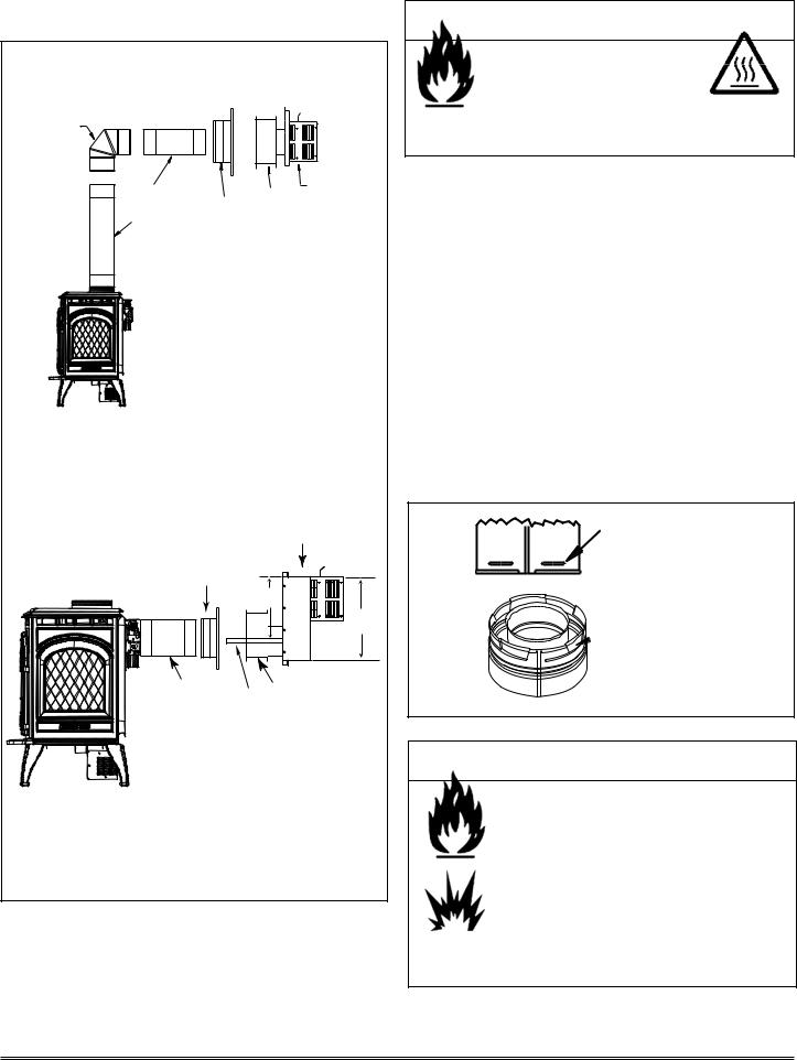
Over 18/12 to 20/12 .......................................... |
7.5 |
Over 20/12 to 21/12 .......................................... |
8.0 |
* 3 foot minimum in snow regions
Figure 4.3 Minimum Height from Roof to Lowest Discharge Opening
Figure 4.3 specifies minimum vent heights for various pitched roofs.
|
Gas Termination |
Wood & Fuel Oil Termination |
A |
6 in. (152mm) |
20 in. (508mm) |
Figure 4.2 Multiple Vertical Termination
Page 8 |
Quadra-Fire · Sapphire · 250-7233F |
January 28, 2008 |
|
|
|
|
|
|
|
|
|
|
|
|
|
|
|
|
|
|
|
|
|
|
|
|
|
|
|
|
|
|
|
|
|
|
|
|
|
|
|
|
|
|
|
|
|
|
|
|
|
|
|
|
|
|
|
|
|
|
|
|
|
|
|
|
|
|
|
|
|
|
|
|
|
|
|
|
|
|
|
|
|
|
|
|
|
|
|
|
|
|
|
|
|
|
|
|
|
|
|
|
|
|
|
|
|
|
|
|
|
|
|
|
|
|
|
|
|
|
|
|
|
|
|
|
|
|
|
|
|
|
|
|
|
|
|
|
|
|
|
|
|
|
|
|
|
|
|
|
|
|
|
|
|
|
|
|
|
|
|
|
|
|
|
|
|
|
|
|
|
|
|
|
|
|
|
|
|
|
|
|
|
|
|
|
|
|
|
|
|
|
|
|
|
|
|
|
|
|
|
|
|
|
|
|
|
|
|
|
|
|
|
|
|
|
|
|
|
|
|
|
|
|
|
|
|
|
|
|
|
|
|
|
|
|
|
|
|
|
|
|
|
|
|
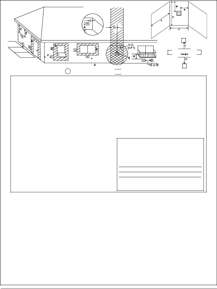
= VENT TERMINAL |
X = AIR SUPPLY INLET |
|||||||||||||||
|
V |
|
|||||||||||||||||
A |
= |
12 inches ............. |
clearances above grade, veran- |
||||||||||||||||
|
|
|
|
|
(See Note 1) |
da, porch, deck or balcony |
|||||||||||||
B |
= |
12 inches ............ |
clearances to window or door |
||||||||||||||||
|
|
|
|
|
|
|
|
|
that may be opened, or to per- |
||||||||||
|
|
|
|
|
|
|
|
|
manently closed window. (Glass) |
||||||||||
D* |
= |
18 inches ............. |
vertical clearance to unventilat- |
||||||||||||||||
|
|
|
|
|
|
|
|
|
ed soffit or to ventilated soffit lo- |
||||||||||
|
|
|
|
|
|
|
|
|
cated above the terminal |
||||||||||
|
|
|
|
|
*30 inches ............ |
for vinyl clad soffits and below |
|||||||||||||
|
|
|
|
|
|
|
|
|
electrical service |
||||||||||
F= 9 inches .............. clearance to outside corner
G= 6 inches ............... clearance to inside corner
H= 3 ft. (Canada) ...... not to be installed above a gas
meter/regulatorassemblywithin 3 feet (90cm) horizontally from the center-line of the regulator
I = 3 ft. ....................... clearance to gas service regula- tor vent outlet
J = 9 inches (U.S.A.)
12 inches (Canada)clearance to non-mechanical air supply inlet to building or the combustion air inlet to any other appliance
**a vent shall not terminate directly above a sidewalk or paved driveway which is located between two single family dwellings and serves both dwellings.
***only permitted if veranda, porch, deck or balcony is fully open on a minimum of 2 sides beneath the floor, or meets Note 2.
NOTE 1: On private property where termination is less than 7 feet above a sidewalk, driveway, deck, porch, veranda or balcony, use of a listed cap is suggested. (See vents components pages.)
NOTE 2: Termination in an alcove space (spaces only open on one side and without an overhang) are permitted with the dimensions specified for vinyl or non-vinyl siding and soffits. 1. There must be at least 3 feet minimum between termination caps. 2. All mechanical air intakes within 10 feet of a termination cap must be a minimum of 3 feet below the termination cap. 3. All gravity air intakes within 3 feet of a termination cap must be a minimum of 1 foot below the termination cap.
NOTE 3: Location of the vent termination must not interfere with access to the electrical service.
Figure 4.4
(See Note 2)
v
v 


 v
v
v
 = AREA WHERE TERMINAL IS NOT PERMITTED
K |
= |
3 ft. (U.S.A.) |
|
|
|
6 ft. (Canada) ......... |
clearance to a mechanical |
|
|
|
(powered) air supply inlet |
L** |
= |
7 ft. ......................... |
clearance above paved |
|
|
(See Note 1) |
sidewalkor a paved driveway |
|
|
|
located on public property |
M*** = |
18 inches .............. |
clearance under veranda , |
|
|
|
|
porch, deck, balcony or over- |
|
|
|
hang |
|
|
42 inches .............. |
vinyl |
S |
= |
6 inches ................. |
clearance from sides of |
|
|
(See Note 3) |
electrical service |
T |
= |
12 inches ................ |
clearance above electrical |
|
|
(See Note 3) |
service |
Alcove Applications
N= 6 inches ................. non-vinyl sidewalls 12 inches ............... vinyl sidewalls
P = 8 ft.
|
QMIN |
RMAX |
1 cap |
3 feet |
2 x Q ACTUA L |
2 caps |
6 feet |
1 x Q ACTUA L |
3 caps |
9 feet |
2/3 x Q ACTUA L _ |
4 caps |
12 feet |
1/2 x Q ACTUA L |
QMIN = # termination caps x 3 RMAX = (2 / # termination caps) x QACTUAL |
||
NOTE: Local codes or regulations may require different clearances.
NOTE: Termination caps may be hot. Consider their proximity to doors or other traffic areas.
WARNING: In the U.S.: Vent system termination is NOT permitted in screened porches. You must follow side wall, overhang and ground clearances as slated in the instructions.
In Canada: Vent system termination is NOT permitted in screened porches. Vent system termination is permitted in porch areas with two or more sides open. You must follow side wall, overhang and ground clearances as stated in the instructions.
Quadra-Fire assumes no responsibility for the improper performance of the appliance when the venting system does not meet these requirements.
CAUTION: IF EXTERIOR WALLS ARE FINISHED WITH VINYL SIDING, IT IS SUGGESTED THAT A VINYL PROTECTOR KIT BE INSTALLED (part #VPKDV).
January 28, 2008 |
Quadra-Fire · Sapphire · 250-7233E |
Page 9 |
5 Vent Information
A. Venting Components
In order to comply with applicable codes and product warranties, use only following venting components:
•Hearth & Home Technologies (HHT)
•Security Chimney's Secure Vent Chimney System
•Selkirk Metalbestos
•AmeriVent
•Simpson Dura-Vent (SDV)
DO NOT USE FIELD-FABRICATED VENTING COMPONENTS. Refer to the venting manufacturer’s instructions.
This product is approved to be vented either horizontally, through the side wall or vertically through the roof. You may vent through a Class A or masonry chimney if an approved adapter is used.
This appliance is a direct vent heater. All combustion air must come directly from the outside of the building. The vent pipe for this unit consists of an inner and an outer pipe. The inner pipe carries the appliance exhaust out of the system, and the outer pipe brings fresh combustion air into the appliance.
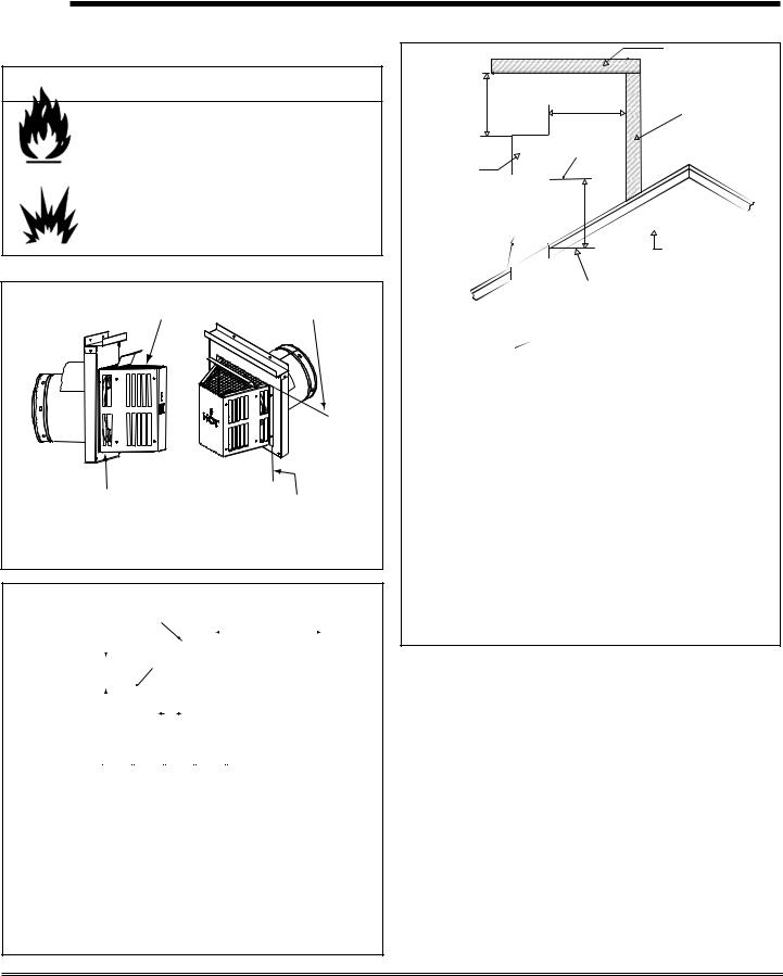
•A round support box/wall thimble or heat shield is required when the venting passes through a combustible wall.
•A support box or ceiling firestop is required when the venting passes through a ceiling.
•Roof flashing and a storm collar are required when venting passes through the roof.
•Follow instructions provided with the venting for installation of these items.
B. Use of Elbows
CAUTION
ALL vent configuration specifications MUST be followed.
•This product is tested and listed to these specifications.
•Appliance performance will suffer if specifications are not followed.
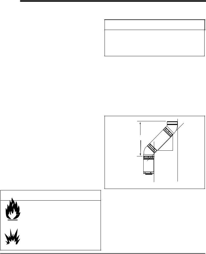
Diagonal runs have both vertical and horizontal vent aspects when calculating the effects. Use the rise for the vertical aspect and the run for the horizontal aspect. (See Figure 5.1.)
Two 45° elbows may be used in place of one 90° elbow. On 45° runs, one foot of diagonal is equal to 8-1/2 in. (216mm) horizontal run and 8-1/2 in. (216mm) vertical run. A length of straight pipe is allowed between two elbows. (See Figure 5.1.)
Vertical
|
|
. |
|
. |
in |
|
1/2 |
|
12 |
in |
|
|
8 |
|
|
|
- |
8-1/2 in.
 Horizontal
Figure 5.1
 WARNING
Fire Hazard. Explosion Risk. Asphyxiation Risk.
Do NOT connect this gas appliance to a chimney flue serving a separate solid-fuel or gas burning appliance.
•Vent this appliance directly outside.
•Use separate vent system for this appliance.
May impair safe operation of this appliance or other appliances connected to the flue.
C. Measuring Standards
Vertical and horizontal measurements were made using the following standards.
•Pipe measurements are from center line to center line.
•Horizontal terminations are measured to the outside of the mounting surface (flange of termination cap). See
Figure 4.1 on page 8.
•Vertical terminations are measured to the top of the last pipe before termination cap.
•Horizontal pipe installed level with 1/4 in. rise.
Page 10 |
Quadra-Fire · Sapphire · 250-7233F |
January 28, 2008 |
D. How to Use the Vent Graph |
E. Venting Guidelines |
1.Measure the distance from the top of appliance to the center of the 90° elbow. On the graph below, draw a horizontal line from that measurement on the vertical axis across until it intersects with the slanted line.
2.From the point of this intersection, draw a vertical line to the bottom of the graph.
3.The point at which this line meets the bottom line of the graph is the maximum length of the horizontal run.
Example 1: If the vertical dimension from the top of the appliance to the center of the 90° elbow is 7 ft. (2m), the horizontal run to the base of the temination cap must not exceed 13 ft.- 2 in. (4m).
Example 2: If the vertical dimension from the top of the appliance is 21 ft. (6m), the horizontal run to the base of the termination cap must not exceed 7 ft.- 3in. (2m).
4.Each 90° elbow is equivalent to 3 ft. (914mm) of vent pipe and each 45° elbow is equivalent to 1 ft. (305mm) of vent pipe, and must be subtracted from vent pipe run. A single vertical to horizontal 90° elbow is already calculated into the allowable 15 ft. (5m) run. Each additional 90° elbow reduces the maximum horizontal distance by 3 ft. (914mm).
Example: The use of 3 elbows would reduce the allowable horizontal run to 9 ft. (3 - 1 = 2 elbows x 3 ft. = 6 ft.; 15 ft. max. - 6 ft.= 9 ft. max.)
Notes: The maximum horizontal vent run is 15 ft. (5m) when the vertical vent rise is 10 ft. (3m).
The minimum horizontal vent run is 11 in. (279mm).
Minimum wall thickness is 4 in. (102mm). Maximum wall thickness is 20 in. (508mm).
Horizontal sections require a 1/4 in. (6mm) rise for every 12 in. (305mm) of horizontal travel.
Exterior Vent Diameter = 6-5/8 in. (168mm); Inner Vent Diameter = 4 in. (101mm).
Horizontal sections require noncombustible support every 3 ft. (914mm), e.g. plumbing tape.
EXCEPTION FOR REAR VENT KIT (Snorkel Kit
#844-8921), HORIZONTAL INSTALLATION:
When installing the Sapphire in a rear vent configuration with no vertical rise: a snorkel kit must be used, and a derating orifice must be installed. The appropriate orifice is supplied with the rear vent kit.
For any vertical rise when rear venting, a minimum of 2 ft. (610mm) vertical must be used prior to any horizontal run.
The maximum horizontal vent run is 2 ft. (610mm).
The maximum horizontal vent run with a 45° elbow is 14 in. (356mm).
No external minimum rise is required. The minimum horizontal vent run is 11 in. (279mm).
NOTE: IF YOUR INSTALLATION FALLS WITHIN A SHADED AREA ON THE GRAPH, THE DAMPER MUST BE USED.
NOTE: In the Commonwealth of Massachusetts, the word damper shall be replaced with the words flue restrictor.
TOP VENT GRAPH |
REAR VENTING WITH VERTICAL RISE |
|
30' |
|
|
|
|
|
|
|
|
|
30' |
|
|
|
|
|
|
28' |
|
|
|
|
|
|
|
|
|
|
|
|
|
|
|
|
|
|
|
|
|
|
|
|
|
28' |
|
|
|
|
|
|
|
26' |
|
|
|
|
|
|
|
|
|
|
|
|
|
|
|
|
|
|
|
|
|
|
|
|
|
26' |
|
|
|
|
|
|
|
24' |
|
|
|
|
|
|
|
|
|
|
|
|
|
|
|
EX. 2 |
|
|
|
|
|
|
|
|
|
24' |
|
|
|
|
|
|
22' |
|
|
|
|
|
|
|
|
|
|
|
|
|
|
||
|
|
|
|
|
|
|
|
|
22' |
|
|
|
|
|
||
|
|
|
|
|
|
|
|
|
|
|
|
|
|
|
||
|
20' |
|
|
|
|
|
|
|
|
|
|
|
|
|
|
|
|
|
|
|
|
|
|
|
|
|
20' |
|
|
|
|
|
|
|
18' |
|
|
|
|
|
|
|
|
|
|
|
|
|
|
|
VERTICAL DISTANCE |
|
|
|
|
|
|
|
|
|
18' |
|
|
|
|
|
|
16' |
|
|
|
|
|
|
|
|
|
|
|
|
|
|
||
FROM APPLIANCE |
14' |
|
|
|
|
|
|
|
|
|
16' |
|
|
|
|
|
TOP TO 90° ELBOW |
|
|
|
|
|
|
|
|
|
14' |
|
|
|
|
|
|
|
12' |
|
|
|
|
|
|
|
|
|
|
|
|
|
|
|
EX. 1 |
10' |
|
|
|
|
|
|
|
|
|
12' |
|
|
|
|
|
8' |
|
|
|
|
|
|
|
|
|
10' |
|
|
|
|
|
|
|
6' |
|
|
|
|
|
|
|
|
|
8' |
|
|
|
|
|
|
4' |
|
|
|
|
|
|
|
|
|
6' |
|
|
|
|
|
|
2' |
|
|
|
|
|
|
|
|
|
4' |
|
|
|
|
|
|
0' |
11" |
2' |
4' |
6' |
8' |
10' |
12' |
14' |
15' |
2' |
|
|
|
|
|
|
(MIN) |
|
|
|
|
|
|
(MAX) |
0' |
|
|
|
|
|
||
|
|
|
TOTAL HORIZONTAL RUN TO BASE OF THE |
|
2' |
4' |
6' |
8' |
10' |
|||||||
|
|
|
|
|
||||||||||||
|
|
|
TERMINATION CAP (EXCLUDING ELBOWS) |
|
(MIN) |
|
|
|
|
(MAX) |
||||||
Figure 5.2
January 28, 2008 |
Quadra-Fire · Sapphire · 250-7233E |
Page 11 |
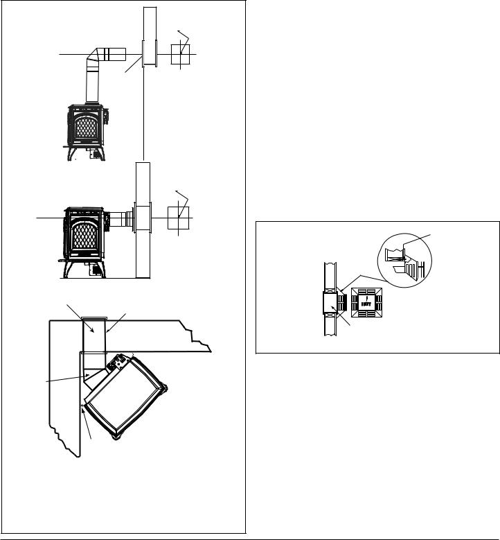
F. Horizontal Termination
Type A - Up & Out Installations for |
Top Vent |
||
Configurations |
|
|
|
90 DEGREE |
|
|
|
ELBOW |
|
|
|
|
|
Temination Cap |
|
PIPE LENGTH |
|
(Recommended |
|
WALL |
for optimum |
||
|
|||
|
WALL THIMBLE |
performance) |
|
PIPE LENGTH |
THIMBLE |
|
|
|
COVER |
|
|
OnhorizontalterminationsuseHearth&HomeTechnologies Part #HHW2, or like components.
Type B - Rear Installations for Use with Rear Vent Kit
SNORKLE KIT
WALL THIMBLE COVER
15-5/8 in. (397mm)
C 21 in. (533mm)
PIPE LENGTH |
WALL THIMBLE |
|
WALL STRAP |
||
|
||
|
14 in. (356mm) Wide |
This is the only venting configuration that requires the use of the rear vent derating orifice that comes with the rear vent kit. NOTE: A Snorkel Kit is required.
Figure 5.3
Step 1.
Determine the desired location of the appliance. Check to ensure that wall studs or roof rafters are not in the way when the venting system is attached. If this is the case, you may want to adjust the location of the appliance.
 WARNING
Fire Hazard.
Exhaust Fume Risk.
Impaired Performance of Appliance.
•Ensure vent components are locked together correctly.
•Pipe may separate if not properly joined.
Step 2.
Direct vent pipe is designed with a locking connection. To connect the venting system to the appliance flue outlet, a twist-lock adapter is built into the appliance at the factory. Wall thickness may vary. Remember to include wall thickness in minimum clearances when figuring venting lengths for your installation needs.
Note: Female ends of direct vent pipe/elbows are designed to slide straight onto the male ends of adjacent pipes by orienting the pipe indentations so they match and slide into the entry slots on the male ends, see Figure 5.4. Push the pipe sections completely together, then twist-lock one section clockwise approximately one-quarter turn, until the two sections are fully locked. The female locking lugs may not be visible from the outside. They may be located by examining the inside of the female ends.
Female Locking Lugs
 Male Locking Lugs
Figure 5.4
 WARNING
Fire Risk. Explosion Risk.
Combustion Fume Risk.
Use vent run supports per installation instructions. Connect vent sections per installation instructions.
•Maintain all clearances to combustibles.
•Do NOT allow vent to sag below connection point to appliance.
•Maintain specified slope (if required).
Improper support may allow vent to sag or separate.
Page 12 |
Quadra-Fire · Sapphire · 250-7233F |
January 28, 2008 |
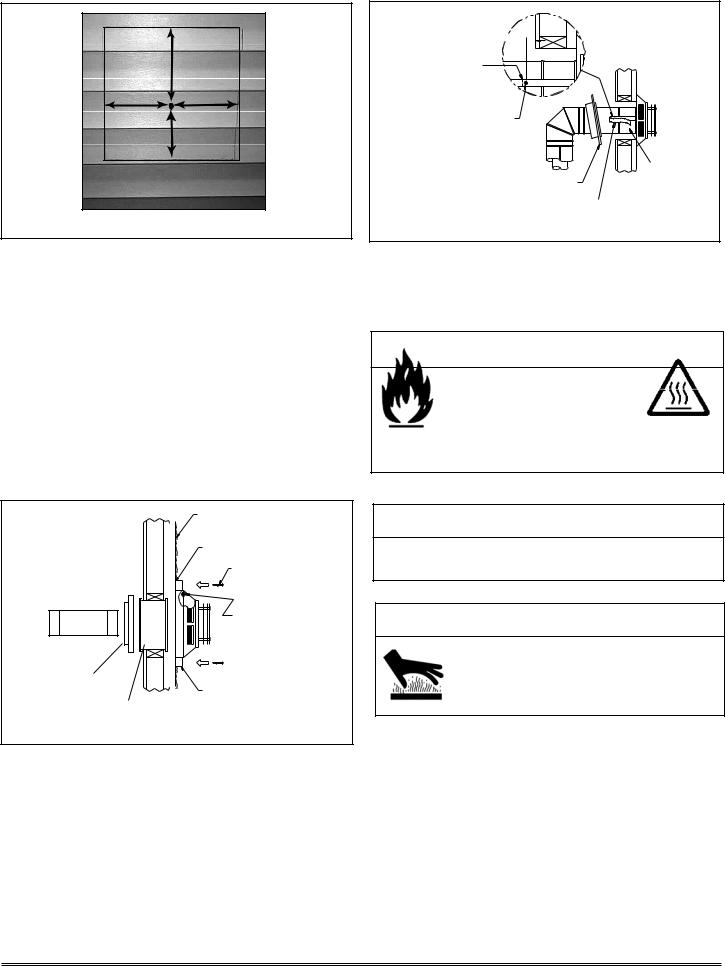
Step 3.
For installations using a round support box/wall thimble (check pipe manufacturer's instructions), mark the wall for a 10 in. x 10 in. (254mm x 254mm) square hole. The center of the square hole should line up with the center line of the horizontal pipe, as shown in Figure 5.5. Cut and frame the hole in the exterior wall where the vent will be terminated. If the wall being penetrated is constructed of noncombustible material, i.e. masonry block or concrete, a 7 in. (178mm) diameter hole is acceptable.
CENTER OF
HOLE
CENTER
LINE
WALL |
CENTER |
|
LINE |
||
THIMBLE |
||
|
||
|
|
CENTER OF
HOLE
CENTER
LINE
CENTER LINE
WALL
THIMBLE
Wall Thimble
14 in. (356mm) Pipe Length
Max. Wall Depth = 10 in. (254mm)
 1 in. (25mm) Clearance from stove corner to combustible wall.
45° Elbow
1 in. (25mm) Clearance from stove corner to combustible wall.
45° Elbow in Corner Installation
When installing the Sapphire in a rear vent configuration with no vertical rise: a Snorkel Kit must be used, and a derating orifice must be installed. The appropriate orifice is supplied with the Rear Vent Kit.
Figure 5.5
NOTE:
(1)Installation requires a minimum of 11 in. (279mm) horizontal run. Each 1 ft. (305mm) of horizontal vent run must include a 1/4 in. (6mm) of vertical rise towards the termination. Never allow the vent to run downward. This could cause high temperatures and may present the possibility of a house or structure fire.
(2)The location of the horizontal vent termination on an exterior wall must meet all local and national building codes, and must not be easily blocked or obstructed, see Figure 4.4 on page 9.
(3)For installations requiring a vertical rise on the exterior of the building, the HHT RHVK snorkel kit (Part #8448921) is available with a 14 in. (356mm) and a 36 in. (914mm) tall snorkel termination cap. Follow the same installation procedures as used for standard horizontal terminations. If the snorkel termination must be installed below grade (i.e. basement application), proper drainage must be provided to prevent water from entering the snorkel termination. Do not backfill around snorkel termination.
Step 4.
Position the horizontal termination cap in the center of the 10 in. x 10 in. (254mm x 254mm) square hole and run a bead of non-hardening mastic around its outside edges, so as to make a seal between it and the wall, attach termination cap to the exterior wall with the four wood screws provided. The arrow on the vent cap should be pointing up (Figure 5.6).
WOOD
SCREW
PART HHW2 PART 841-0670 (Preferred)
WALL THIMBLE
Figure 5.6
NOTES:
(1)The four wood screws provided should be replaced with appropriate fasteners for stucco, brick, concrete, or other types of sidings.
(2)Termination cap HHW2 (Part #841-0670) is highly recommended on a building with vinyl siding, as the vinyl siding standoff is built in. The pilot hole will be 2 in. (51mm) closer to the bottom of the square than the top. Using a framing square, draw a 14 in. x 14 in. (356mm x 356mm) square around the pilot hole in the siding. See Figure 5.7 on the next page.
January 28, 2008 |
Quadra-Fire · Sapphire · 250-7233E |
Page 13 |
8 in.
(203mm)
7 in.
(178mm)
7 in.
(178mm) |
6 in. |
(152mm)
Figure 5.7
1/4 in. (6mm) 
FOLD STRAP
HERE
SHEET METAL SCREW
WALL WALL THIMBLE COVER/CEILING THIMBLE FIRESTOP AS REQUIRED BY
LOCAL JURISDICTION
STRAP
Figure 5.9
(NOTE: If you are installing termination cap HHW2, the pipe will be off center on flashing). Ensure that proper clearances to combustible materials are maintained. If you are using an approved termination cap other than HHW2 (part #841-0670) on a building with vinyl siding, a vinyl siding standoff should be installed between the termination cap and the exterior wall (Figure 5.8). Follow manufacturer’s instructions for attaching the vinyl siding standoff to the horizontal termination cap. The vinyl siding standoff prevents excessive heat from possibly melting the vinyl siding material. The vent terminal cap shall not be recessed into a wall or siding. Remove siding from the area where the standoff will be located.
|
|
VINYL SIDING |
|
|
APPLY SEALANT TO ALL |
|
|
FOUR SIDES |
|
|
SCREWS |
|
|
BOLT HORIZONTAL TOP |
|
|
TO VINYL STANDOFF |
WALL THIMBLE |
|
SCREWS |
|
|
|
COVER |
|
VINYL SIDING STANDOFF |
|
|
|
|
WALL THIMBLE |
WITH SIDING BENEATH |
|
REMOVED |
|
|
|
Figure 5.8
Note: The attachment from the vent pipe to the vent termination cap must be sealed with silicone. Termination caps shall not be recessed into a wall or siding.
 WARNING
Fire Hazard.
Exhaust Fume Risk.
Impaired Performance of Appliance.
•Ensure vent components are locked together correctly.
•Pipe may separate if not properly joined.
 WARNING
Do NOT connect a pipe section to a termination cap without using the telescoping flue section found on the termination cap.
 WARNING
Burn Risk.
•Local codes may require installation of a cap shield to prevent anything or anyone from touching the hot cap.
Step 5.
Place the wall thimble cover over the pipe assembly and slide the appliance and vent assembly towards the wall, carefully inserting the vent pipe into the vent termination cap assembly. It is important that the vent pipe extend into the vent termination cap a sufficient distance so as to result in a minimum pipe overlap of 1-1/4 in. (32mm). Secure the connection between the vent pipe and the vent termination cap by attaching the two sheet metal strips extending from the vent termination cap assembly into the outer wall of the vent pipe. Use the two sheet metal screws provided to connect the strips to the pipe section (Figure 5.9).
Page 14 |
Quadra-Fire · Sapphire · 250-7233F |
January 28, 2008 |
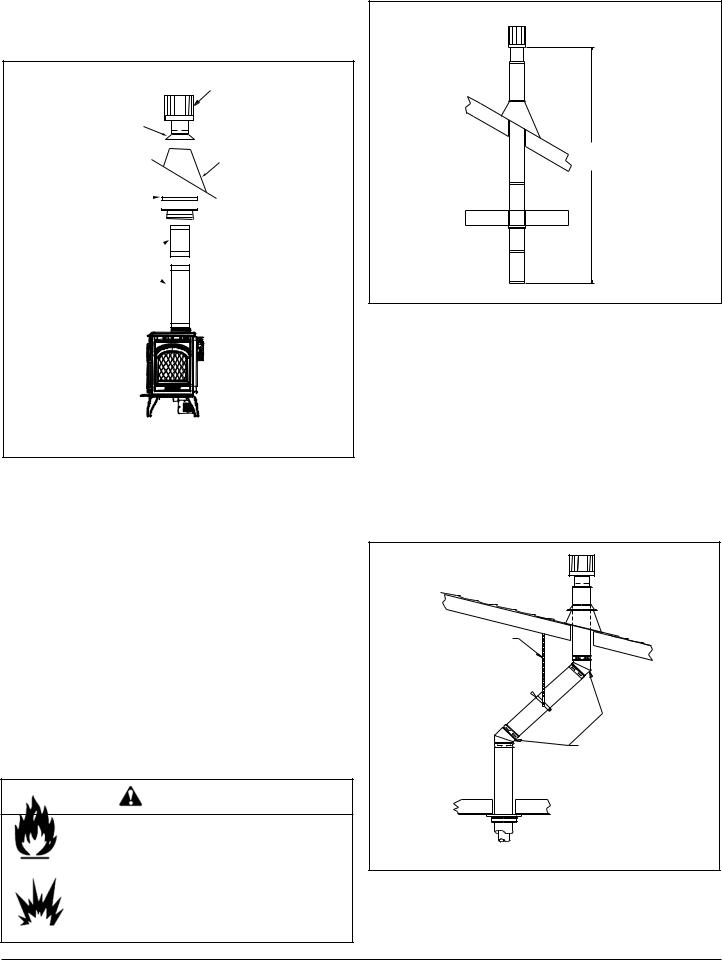
G. Vertical Termination
1. Direct Vent Pipe
VERTICAL
TERMINATION
CAP
STORM
COLLAR
FLASHING
FIRESTOP
 SUPPORT
BOX
PIPE
LENGTH
Figure 5.10
Step 1.
Check the installation instructions for required 1 in. (25mm) clearances (air space) to combustibles when passing through ceilings, walls, roofs, enclosures, attic rafters, or other nearby combustible surfaces. See page 16, Figure 5.15. Check the instructions for maximum vertical rise of the venting system, and any maximum horizontal offset limitations. All offsets must fall within the set parameters of the vent graph (Figure 5.2) located on page 11.
NOTE: Maximum vertical rise allowable is 35 ft. (11m)
Figure 5.11).
NOTE: Maximum number of 45° elbows permitted for a vertical installation is eight, provided their installation does not decrease maximum allowable horizontal run (as specified by vent graph, on page 11).
WARNING
Fire Risk. Explosion Risk.
Maintain vent clearance to combustibles as specified.
•Do not pack air space with insulation or other materials.
Failure to keep insulation or other materials away from vent pipe may cause fire.
35 ft. (11m) MAXIMUM
Figure 5.11
Step 2.
Set the gas appliance in its desired location. Drop a plumb bob down from the ceiling to the position of the appliance flue exit, and mark the location where the vent will penetrate the ceiling. Drill a small hole at this point. Next, drop a plumb bob from the roof to the hole previously drilled in the ceiling, and mark the spot where the vent will penetrate the roof. Determine if ceiling joists, roof rafters, or other framing will obstruct the venting system. You may wish to relocate the appliance, or to offset, as shown in Figure 5.12 to avoid cutting loadbearing members. When location is determined, drill small hole.
PLUMBER'S TAPE
CONNECTED TO
WALL STRAP
WALL 
STRAP
TWO 45 DEGREE
ELBOWS
Figure 5.12
January 28, 2008 |
Quadra-Fire · Sapphire · 250-7233E |
Page 15 |
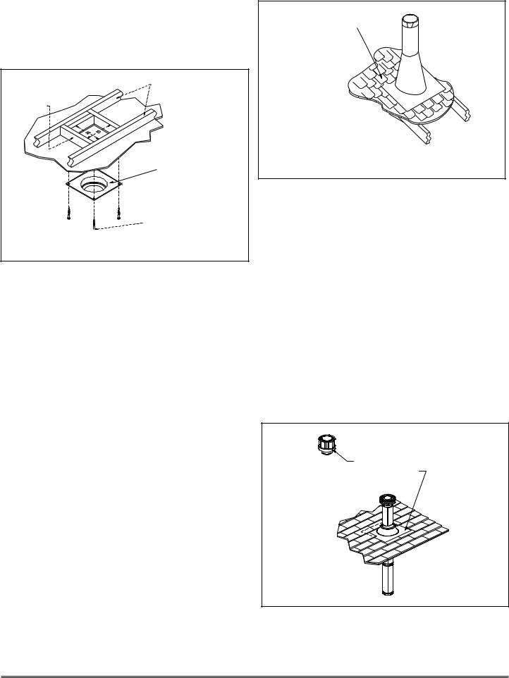
Step 3.
To install the round support box/wall thimble cover in a flat ceiling, cut a 10 in. (254mm) square hole in the ceiling, centered on the hole drilled in Step 2. Frame the hole as shown in Figure 5.13.
CEILING JOISTS
FRAMING
ROUND CEILING
SUPPORT BOX/WALL
THIMBLE COVER
 1-1/2 in. (38mm) LONG
WOOD SCREWS
Figure 5.13
Step 4.
Assemble the desired lengths of pipe and elbows necessary to reach from the appliance up through the round support box. Ensure that all pipe and elbow connections are in their fully twist-locked position. Assemble as instructed.
Step 5.
Cut a hole in the roof centered on the small drill hole placed in the roof in Step 2. The hole should be of sufficient size to meet the minimum requirements for clearance to combustibles, as specified. Continue to assemble lengths of pipe and elbows necessary to reach from the ceiling support box/wall thimble up through the roof line. Galvanized pipe and elbows may be utilized in the attic, as well as above the roofline. The galvanized finish is desirable above the roofline, due to its higher corrosion resistance.
NOTE:
(1) If an offset is necessary in the attic to avoid obstructions, it is important to support the vent pipe every 3 ft. (914mm) to avoid excessive stress on the elbows, and possible separation. Wall straps are available for this purpose, Figure 5.12, page 15.
(2)Whenever possible, use 45° elbows, instead of 90° elbows. The 45° elbow offers less restriction to the flow of flue gases and intake air.
Step 6.
Slip the flashing over the pipe section(s) protruding through the roof. Secure the base of the flashing to the roof with roofing nails. Ensure the roofing material overlaps the top edge of the flashing as shown in Figure 5.14. Verify that the chimney is the required height above the roof. See roof pitch table, Figure 4.3, on page 8.
SHINGLES OVERLAP ON
TOP EDGE OF FLASHING
CAP AND STORM COLLAR NOT SHOWN FOR CLARITY
Figure 5.14
Step 7.
Continue to assemble pipe sections until the height of the vent (before adding the termination cap) meets the minimum code requirements as outlined in the current CAN/CGA-B149 Installation Codes (in Canada), the National Fuel Gas Code NFPA 54/ANSI Z223.1 (in USA), or local codes. Note that for steep roof pitches, the vent height must be increased. See Roof Pitch Table (Figure 4.3, on page 8). In high wind conditions, nearby trees adjoining rooflines, steep pitched roofs, and other similar factors can result in poor draft, or down drafting. In these cases increasing the vent height or switching to the high wind termination cap may solve this problem.
Step 8.
Slip the storm collar over the pipe, and push it down to the top of the flashing (Figure 5.15). Use non-hardening sealant above and below the joint between the storm collar and the pipe.
OPTIONAL HIGH WIND
TERMINATION CAP
SECURE FLASHING WITH
NON-HARDENING SEALANT
AND ROOFING NAILS
Figure 5.15
Page 16 |
Quadra-Fire · Sapphire · 250-7233F |
January 28, 2008 |
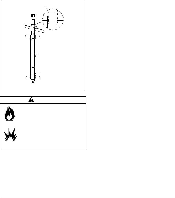
Step 9.
Twist-lock the vent cap and seal.
Note: For multi-story vertical installations, a ceiling firestop is required at the second floor, and any subsequent floors (Figure 5.16). The opening should be framed to 10 in. x 10 in. (254mm x 254mm) inside dimensions, in the same manner as shown in Figure 5.13, page 16.
NAILS
CEILING FIRES TOP
MIN. 1 in. (25mm) 
CLEARANCE
MIN. 1 in. (25mm) 
CLEARANCE
MIN. 1 in. (25mm)
CLEARANCE
MIN. 1 in. (25mm)
CLEARANCE
Figure 5.16
WARNING
Fire Risk.
Explosion Risk.
•Any occupied areas above the first floor, including closets and storage spaces, which the vertical vent passed through must be enclosed. The enclosure may be framed and sheetrocked with standard construction materials; however, refer to these installation instructions for the minimum allowable clearance between the outside of the vent pipe and the combustible surfaces of the enclosure. Do not fill any of the required air space with insulation.
January 28, 2008 |
Quadra-Fire · Sapphire · 250-7233E |
Page 17 |
 Loading...