


CONTOUR PELLET STOVE
INSTALLATION, OPERATION, AND MAINTENANCE INSTRUCTIONS
IMPORTANT! Record serial number of your stove on the warranty card and mail immediately.
The serial number is located on the safety label affixed behind the left side curtain on the outside of hopper wall.
Please read this entire manual before installation and use of this pellet fuel room heater.
Failure to follow these instructions could result in property damage, bodily injury or even death.
IMPORTANT SAFETY NOTES
1.When installing your stove, particular attention should be paid to fire protection. If this unit is not properly installed, a house fire may result. For your safety, follow the installation instructions, and contact local building or fire officials about restrictions and installation inspection required in your area.
2.Read power supply section of component information (page 15) before you plug in the stove.
3.Always unplug the stove before cleaning or servicing.
4.During operation, if any part of the stove starts to glow, the stove is in an overfired condition. Reduce the feed rate and increase the amount of air going into the stove. OVERFIRING VOIDS WARRANTY.
5.Do not install a flue damper in the exhaust venting system of this unit.
6.Do not connect the stove to a chimney flue already serving another appliance.
7.Never use gasoline, gasoline-type lantern fuel, kerosene, charcoal lighter fluid, or similar liquids to start or freshen up a fire in this heater. Keep all such liquids well away from the heater while it is in use.
8.The stove operates with a negative pressure firebox and a positive pressure exhaust. It is imperative that the chimney system be airtight and installed correctly.
9.Dispose of all ashes in a metal container.
10.Comply with all minimum clearances to combustibles as shown on page 5.
11.The Quadra-Fire Contour is tested and approved for pelleted biomass fuel or shelled field corn only. Burning of any other type of fuel voids your warranty!
12.Aladdin Hearth Products, manufacturer of the Contour pellet stove, reserves the right to alter its products, their specifications and/or price without notice.
13.ALADDIN HEARTH PRODUCTS, GRANTS NO WARRANTY, IMPLIED OR STATED, FOR THE INSTALLATION OR MAINTENANCE OF THIS UNIT AND ASSUMES NO RESPONSIBILITY FOR ANY CONSEQUENTIAL DAMAGE(S).
PRIOR TO FIRST FIRE: Remove all labels from glass. Clean gold surfaces with a glass cleanser and soft cloth to prevent staining from fingerprint oils.
Tested and |
O-T L |
Beaverton |
Listed by |
Oregon USA |
|
|
C |
|
OMNI-Test Laboratories, Inc. |
||
1445 N. Highway |
SAVE THESE INSTRUCTIONS |
|
||
250-5583 |
October 10, 2001 |
www.aladdinhearth.com |
||
Colville, WA 99114 |
||||
|
|
|
||

Contour Pellet Stove
Aladdin Hearth Products welcomes you to our tradition of excellence! In choosing a Quadra-Fire appliance, you have our assurance of commitment to quality, durability, and performance.
This commitment begins with our research of the market, including ‘Voice of the Customer’ contacts, ensuring we make products that will satisfy your needs. Our Research and Development facility then employs the world’s most advanced technology to achieve the optimum operation of our stoves, inserts and fireplaces. And yet we are old-fashioned when it comes to craftsmanship. During manufacturing each unit is meticulously fabricated and gold surfaces are hand-finished for lasting beauty and enjoyment. Our pledge to quality is completed as each model undergoes a quality control inspection. Additionally, we feel it is important to offer you several finishing options and accessories to compliment your home’s décor, individualize the use of your appliance, and provide financial options in acquiring a quality hearth appliance. Ask your Quadra-Fire Dealer for information on these options. From design, to fabrication, to shipping: Our guarantee of quality is more than a word, it’s Quadra-Fire tradition, and we proudly back this tradition with a Lifetime Warranty.
Prior to installation, we ask you to take a few moments to read this manual. It has been our experience that your overall enjoyment of your new appliance will be greatly enhanced by becoming familiar with its’ installation, operation and maintenance requirements. We wish you and your family many years of enjoyment in the warmth and comfort of your hearth appliance.
Thank you for choosing Quadra-Fire.
With warm regards,
Marketing & Product Planning
_______________________
Order Fulfillment Manager
October 10, 2001 |
2 |
250-5583 |
Contour Pellet Stove
MODEL NAME CONTOUR Pellet Stove
Serial Number
Date Purchased
Dealership Where Purchased
Dealer Phone
Additional Information:
AFTER COMPLETINGYOUR WARRANTY CARD, ATTACH YOUR SALES RECEIPT AND WARRANTY STUB HERE FOR FUTURE REFERENCE.
TABLE OF CONTENTS |
|
|
Page |
Safety Label......................................................... |
4 |
Safety Label Location............................................. |
4 |
Clearances to Combustibles................................ |
5 |
Floor Protection Requirements............................ |
5 |
Listings and Specifications .................................. |
5 |
Dimensions.......................................................... |
5 |
Chimney and Exhaust Connections .................... |
6 |
Venting Termination Requirements...................... |
6 |
Venting Graph and Pipe Table ............................. |
6 |
Venting Systems |
|
A. Alcove...................................................... |
7 |
B. Through the Wall...................................... |
7 |
C. Vertical..................................................... |
8 |
D. Through the Wall and Vertical .................. |
8 |
E. Masonry................................................... |
8 |
F. Alternate masonry.................................... |
8 |
Top Vent Adapter ................................................. |
9 |
Feed Adjustment Instructions .............................. |
9 |
Log Placement Instructions ................................. |
10 |
Mobile Home Installation ..................................... |
11 |
Thermostat Installation ........................................ |
11 |
Operating Instructions ......................................... |
11-12 |
Cleaning and Maintenance.................................. |
13-14 |
Component Information ....................................... |
15-17 |
Troubleshooting ................................................... |
18-20 |
Wiring Harness.................................................... |
20 |
Outside Air Kit Installation Instructions................ |
21 |
Trim Ring Installation Instructions........................ |
22-23 |
Gold Grille Installation Instructions...................... |
23 |
Exhaust Blower Replacement Instructions .......... |
24 |
Feed Motor Replacement Instructions................. |
24 |
Rear Screen Replacement Instructions............... |
25 |
Top Baffle Removal Instructions .......................... |
25 |
Accessories and Service Parts............................ |
26 |
Warranty .............................................................. |
27 |
Warranty card ...................................................... |
Insert |
October 10, 2001 |
3 |
250-5583 |
Contour Pellet Stove
SAFETY LABEL
LABEL LOCATION: BEHIND LEFT SIDE CURTAIN ON OUTSIDE OF HOPPER
OMNI-Test Labs, Inc.
Beaverton, OR
Report No. 061-S-20-2
Tested and |
O-T L |
Beaverton |
Listed by |
Oregon USA |
C
OMNI-Test Laboratories, Inc.
'PREVENT HOUSE FIRES"
Model: |
Serial No. |
QUADRA-FIRE CONTOUR |
|
Room Heater Pellet Fuel BurningType
Also for use in Mobile Homes. This pellet burning appliance has been tested and listed for use in Manufactured Homes in accordance with
OAR 814-23-900 through 814-23-909
1445 North Highway
Colville, WA 99114
Install and use only in accordance with manufacturer's installation and operating instructions. Contact Local Building or Fire Officials About Restrictions and Inspection in Your Area.
WARNING - FOR MANUFACTURED HOMES: Do not install appliance in a sleeping room. An outside combustion air inlet must be provided. The structural integrity of the manufactured home floor, ceiling and walls must be maintained.
Refer to manufacturer's instructions and local codes for precautions required for passing chimney through a combustible wall or ceiling. Inspect and clean exhaust venting system frequently in accordance with manufacturer's instructions.
Use a 3" or 4" diameter type "L" or "PL" venting system.
Do not connect this unit to a chimney flue servicing another appliance.
Tested to:
ASTM E 1509, and ULC-C1482-M1990 Room Heater Pellet Fuel Burning type (UM) 84-HUD
Input Rating Max 4 lb. fuel/hr.
Electrical Rating: 115 VAC, 60 Hz, Start 4.1 Amps, Run 1.1 AMPS. Route power cord away from unit
DANGER: Risk of electrical shock. Disconnect power supply before servicing.
Replace glass only with 5mm ceramic available from your dealer
To start, set thermostat above room temperature, the stove will light automatically. To shutdown, set thermostat to below room temperature. For further instruction refer to owner's manual.
Keep viewing and ash removal doors tightly closed during operation.
FOR USE WITH PELLETIZED WOOD FUELOR SHELLED FIELD CORN ONLY.
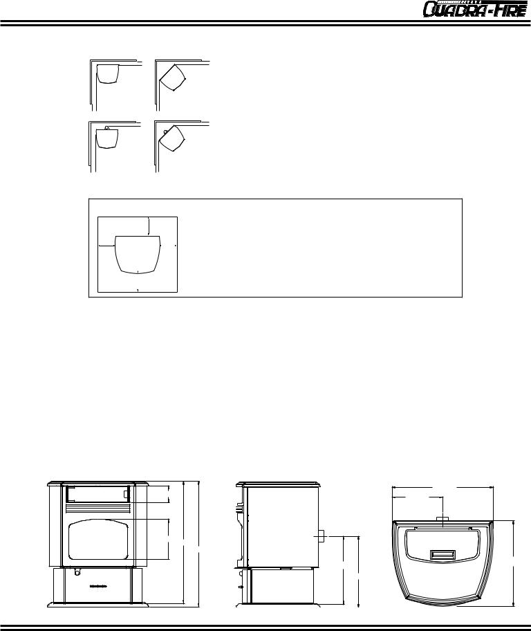
Minimum Clearances to Combustible Materials
AC
BC
DF
|
E |
F |
|
|
A |
Back Wall to Appliance |
2"/5cm |
||
B |
Side Wall to Appliance |
|
6"/15cm |
|
Corner Installation: |
|
|
|
|
C |
Walls to Appliance |
|
2"/5cm |
|
Vertical 3" - 6" Adapter Kit (Part #812-3570) Installation: |
||||
D |
Back Wall to Appliance Flue |
3"/8cm |
||
E |
Side Wall to Appliance |
|
6"/15cm |
|
Corner Installation with Vertical Adapter Kit: |
||||
F |
Walls to Appliance |
|
2"/5cm |
|
Alcove Installation: |
|
|
|
|
Min. Alcove Height: |
|
43"/1092cm |
||
Min. Alcove Side Wall |
|
6"/15cm |
||
Max. Alcove Depth |
|
36"/91cm |
||
FLOOR PROTECTION
*H
GG
I
G = 2"/5cm
H = 2"/5cm *See Exceptions Below
I = 6"/15cm
Use a non-combustible floor protector extending under unit and to the sides, front and back of unit as shown in Floor Protection Diagram. Measure front distance
(I) from the surface of the glass door.
*Exceptions: Non-combustible floor protection must extend beneath the fluepipe when installed with horizontal venting or under the top vent adapter with vertical installation.
Note 1: In residential installations, when using parts #811-0860, (3" - 3" Top Vent Adapter) and #812-3570 (3" - 6" Offset Adapter), 24 gauge 6" single wall flue connector may be used.
Note 2: In manufactured home installation, when using part #811-0860, (3" - 3" Top Vent Adapter) and #812-3570 (3' - 6" Offset Adapter), use listed double wall flue connector. An Outside Air Kit (#811-0871), must be used with manufactured home installation.
U.S. ENVIRONMENTAL PROTECTION AGENCY
This model is exempt from EPA certification under 40 CFR 60.531 by definition [Wood Heater (A) "Air-to-Fuel Ratio"]. Date of Manufacture
2000 2001 2002 JAN FEB MAR APR MAY JUNE JULY AUG SEPT OCT NOV DEC
DO NOT REMOVE THIS LABEL |
MADE IN U.S.A. |
October 10, 2001 |
4 |
250-5583 |
Contour Pellet Stove
CLEARANCES TO COMBUSTIBLES
AC
BC
D F
EF
A |
Back Wall to Appliance 2"/5cm |
|
|
B |
Side Wall to Appliance 6"/15cm |
|
|
Corner Installation: |
|
|
|
C |
Walls to Appliance |
2"/5cm |
|
Vertical 3" - 6" Adapter Kit (Part #812-3570) Installation: |
|||
D |
Back Wall to Appliance Flue |
3"/8cm |
|
ESide Wall to Appliance 6"/15cm
Corner Installation with Vertical Adapter Kit:
F Walls to Appliance |
2"/5cm |
Alcove Installation: |
|
Min. Alcove Height: |
43"/1092cm |
Min. Alcove Side Wall |
6"/15cm |
Max. Alcove Depth |
36"/91cm |
FLOOR PROTECTION
*H
|
|
|
|
|
G = |
2"/5cm |
Measure front distance (I) from the surface of the glass |
G |
|
|
|
G |
H = 2"/5cm |
door. |
|
|
|
|
|
||||
|
|
|
|
|
|
*See Exceptions*Exceptions: Non-combustible floor protection must |
|
|
|
|
|
|
I = |
6"/15cm |
extend beneath the flue pipe when installed with |
|
|
|
|
|
|||
|
|
|
|
|
|||
|
I |
|
|
|
|
|
horizontal venting or under the Top Vent Adapter with |
|
|
|
|
|
|
|
vertical installation. |
|
|
|
|
|
|
|
|
LISTINGS AND SPECIFICATIONS
The QUADRA-FIRE CONTOUR pellet stove is safety listed with OMNI-Test Labs, Inc., Beaverton, OR, to ASTM E 1509 and ULC-C1482-M1990 Room Heater Pellet Fuel Burning type (UM) 84-HUD. Also suitable for use in mobile homes. See pages 5 and 9 for mobile home installation details.
HEAT OUTPUT*: 8,000 to 30,000 BTUs per hour
*BTU output will vary, depending on the brand of fuel you use in your stove. Consult your Quadra-Fire dealer for best results.
DIMENSIONS |
|
|
|
|
25-7/16 |
4-1/8 |
|
12-23/32 |
|
|
|
10 |
30-5/8 |
|
|
31-1/2 |
|
|
17-1/16 |
21-7/16 |
|
|
|
|
17-15/16 |
|
October 10, 2001 |
5 |
250-5583 |
Contour Pellet Stove
CHIMNEY AND EXHAUST CONNECTION
1.Chimney & Connector: Use 3" (76mm) or 4" (102mm) diameter type "L" or "PL" venting system.
2.Mobile Home: Approved for all listed pellet vent. If using the 3" (76mm) vertical Top Vent Adapter Kit (part #811-0860), or the 3" (76mm) to 6" (152mm) Offset Collar (part #812-3570), use listed double wall flue connector. An Outside Air Kit (part #811-0871), must be used with manufactured home installation.
3.Residential: The 3" (76mm) vertical Top Vent Adapter Kit (#811-0860), and 3" (76mm) to 6" (152mm) Offset Collar (part #812-3570), are tested to use 24 gauge single wall flue connector or listed double wall flue connector to Class A listed metal chimneys, or masonry chimneys meeting ICBO standards for solid fuel appliances.
4.The stove is approved for all 3" (76mm) or 4" (102mm) diameter listed pellet vent. It can be either vertically or horizontally vented.
5.Install vent at clearances specified by the vent manufacturer.
6.Be sure to secure exhaust venting system to the stove with at least three set screws. Also secure all connector pipe joints with at least three screws through each joint.
NOTE: All pipe must be sealed using welded seam pipe whenever possible. Seal pipe joints with high temperature silicone (500°F [260°C] minimum rated only).
VENT TERMINATION REQUIREMENTS
1.Do not terminate vent in any enclosed or semi-enclosed area such as a carport, garage, attic, crawl space, under a sun deck or porch, narrow walkway or closely fenced area, or any location that can build up a concentration of fumes such as a stairwell, covered breezeway, etc.
2.Vent surfaces can get hot enough to cause burns if touched. Noncombustible shielding or guards may be required.
3.Termination must exhaust above air inlet elevation. It is recommended that at least 5' (1.5m) of vertical pipe be installed when appliance is vented directly through a wall. This will create a natural draft, which will help prevent the possibility of smoke or odor venting into the home during appliance shutdown. It will also keep exhaust from causing a nuisance or hazard by exposing people or shrubs to high temperatures. The safest and preferred venting method is to extend the vent vertically through the roof.
4.Venting should terminate not less than 4' (1.2m) below, not less than 4' (1.2m) horizontally from, and not less than 1' (305mm) above doors and windows, or gravity or ventilation air inlets into the building.
5.Distance between bottom of termination and grade should be 1' (305mm) minimum. This is conditional upon plants in the area, and nature of grade surface. The grade surface must be a noncombustible material (i.e., rock, dirt). Distance between bottom of termination and public walkway should be 7' (2.1m) minimum.
6.Distance to combustible materials should be 2' (51mm) minimum. This includes adjacent buildings, fences,
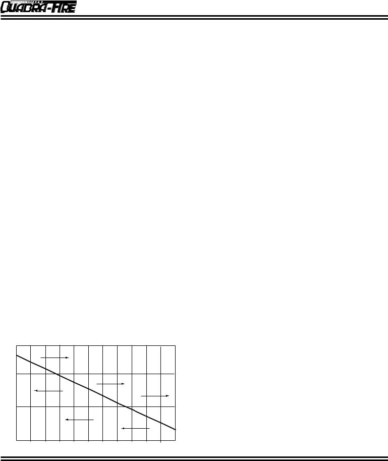
VENTING GRAPH
When running vertically with pellet venting, the following chart can be used to determine whether to use 3" or 4"
(7.6cm or 10.2cm) diameter pipe
IN FEET |
30 |
|
|
|
|
|
|
|
|
|
|
|
|
|
|
4" (102mm) Diameter Pipe Only |
|||||
|
|
|
|
|
|
|
|
|
|
|
PIPE LENGTH |
20 |
|
|
|
|
|
|
|
|
|
|
|
|
|
|
|
|
|
|
|
|
EQUIVALENT |
10 |
|
|
|
|
|
|
|
|
|
|
3" or 4" (76mm or 102mm) Diameter Pipe |
|
|
|
||||||
|
|
|
|
|
||||||
|
0 |
|
|
|
|
|
|
|
|
|
|
1 |
2 |
3 |
4 |
5 |
6 |
7 |
8 |
9 |
10 |
ALTITUDE IN THOUSANDS OF FEET
VENTING PIPE TABLE
The table below can help you determine the equivalent feet of pipe used for venting when installing a pellet appliance.
Pellet Venting |
# of Elbows or |
Multiplied |
Equivalent |
Component |
Component |
Feet of Pipe |
By: |
Feet |
Equivalent Feet |
|
|
|
|
|
90° Elbow or Tee |
|
x |
5 |
|
45° Elbow |
|
x |
3 |
|
Horizontal Pipe |
|
x |
1 |
|
Vertical Pipe |
|
x |
.5 |
|
|
Total Equivalent Feet: |
|
||
October 10, 2001 |
6 |
250-5583 |

Contour Pellet Stove
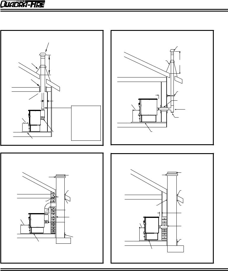
VENTING SYSTEMS
A. ALCOVE
The Quadra-Fire Contour is approved for minimum alcove height of 43” (109.2cm), and a maximum alcove depth of 36” (91cm).
All minimums listed are to a combustible surface.
43" (109.2cm)
Minimum
6" (15.2cm) Minimum
Maximum Alcove Depth: 36"/91cm
B. THROUGH THE WALL
We recommend going a minimum 5' (15.25cm) vertical, but above the eave is preferred. Horizontal termination must be 1' (30.5cm) from the wall.
Straight Out |
45 Degree |
|
2" (52mm) |
Wall |
|
Minimum |
|
|
Wall Thimble |
Thimble |
|
|
|
6" (152mm) |
Horizontal Cap |
2" (51mm) |
Minimum |
|
Minimum |
From Glass |
|
|
|
|
Optional |
|
|
Direction |
|
12" (305mm) |
|
|
Minimum |
2" (51mm) |
|
Insulating Hearth Pad |
|
|
Minimum |
|
October 10, 2001 |
7 |
250-5583 |
Contour Pellet Stove
VENTING SYSTEMS, CONT'D.
C. VERTICAL
Rain Cap
Flashing
24" (61cm) minimum
Firestop


 Class A Chimney
Ceiling Support
Connector Adapter
3" (7.6cm) Min.
 Top Vent Kit
6" (15.2cm) Min.
Cleanout
Cover
Non-combustible Hearth Pad
6" Flue Connector (Single Wall for residential installation. Double Wall for mobile home installation.) OR
3" or 4" L Vent (For residential or mobile home installation.)
D. THROUGH THE WALL & VERTICAL
|
Rain Cap |
|
Flashing |
|
24" (610mm) minimum |
|
Support Bracket |
2" (50mm) minimum |
(every 60" [152.4cm]) |
Wall Thimble
6" (152mm) minimum
Tee
Cleanout Cover
Non-combustible Hearth Pad
E. MASONRY
Concrete Cap |
Fireclay flue |
|
liner with airspace |
||
|
||
|
Flashing |
1" (25mm) clearance
with firestop
1" (25mm) clearance
3" (76mm) minimum
6" (152mm) |
Sheathing |
minimum
Cleanout cover
Airtight
Cleanout Door
Non-combustible Hearth Pad
F. ALTERNATE MASONRY
Concrete Cap |
Fireclay Flue Liner |
|
with airspace |
||
|
Flashing
1" (25mm) clearance |
1" (25mm) clearance |
|
with firestop |
||
|
||
|
2" (50mm) minimum |
6" (152mm) minimum
Sheathing
Airtight cleanout door
Non-combustible
Hearth Pad
October 10, 2001 |
8 |
250-5583 |
Contour Pellet Stove
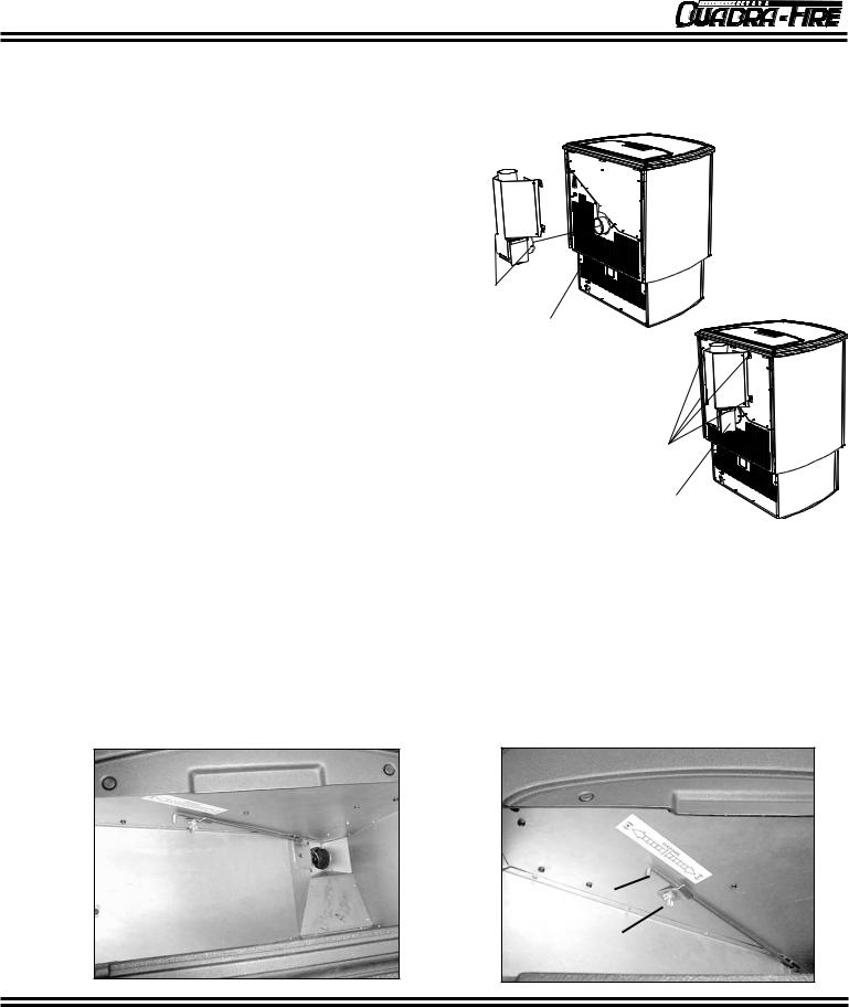
TOP VENT FLUE ADAPTER INSTALLATION
Part #811-0860, 3"-3" Top Vent Adapter or Part #812-3570, 3"-6" Offset Collar
1)Put a layer of silicone on the 3" (76mm) exhaust outlet.
2)Slide the flue adapter onto the rear exhaust outlet.
3)Adjust the assembly to a vertical position.
4)Drill four holes with #26 drill bit (provided) into the back of the stove using the outer shield as a pattern (make sure the assembly is vertical).
5)Install the four mounting screws.
6)Drill two holes with #26 drill bit through the Rear Exhaust Outlet using the two holes already in the short horizontal pipe in the Top Vent Adapter as a guide. Install the two screws
7)Install the stove pipe into the adapter (be sure to silicone all joints).
8)To clean adapter, remove cleanout cover.
Use hole on each side as drilling guide
Rear Exhaust
Outlet
Mount with four screws
FEED ADJUSTMENT
NOTES:
The feed adjustment rod is factory set, and should be adequate for most fuels. However, if the flame height is too high or too low, follow the instructions below.
Loosen the set screw (Fig. 1) 1/4 to 1/2 turn during set-up of stove. This will allow movement of the Fuel Adjustment Rod. Do not re-tighten set screw.
Adjust fuel adjustment rod after the stove has been burning for 10-15 minutes. The flames should be approximately 4"(102mm) above the firepot at high heat output setting.
Cleanout Cover
1)Loosen the wing nut.
2)Adjust the fuel adjustment rod upward towards the "+" symbol, to increase the feed rate and flame height, or down towards the "-" symbol, to decrease the feed rate and flame height.
3)Re-tighten the wing nut.
FIGURE 1 |
FIGURE 2 |
Fuel Adjustment Rod
Wing Nut
October 10, 2001 |
9 |
250-5583 |
 Loading...