


R
CLASSIC BAY 1200 PELLET STOVE
Owner’s Manual
Installation and Operation
Model:
CB1200M-MBK
Tested and |
O-T L |
Portland |
Listed by |
Oregon USA |
C US
OMNI-Test Laboratories, Inc.
NOTICE
DO NOT DISCARD THIS MANUAL
• Important operating and |
• Read, understand and |
• Leave this manual with |
maintenance instruc- |
follow these instruc- |
party responsible for use |
tions included. |
tions for safe installa- |
and operation. |
|
tion and operation. |
|
DO DISCARDNOT
 WARNING
Please read this entire manual before installation and use of this pellet fuel-burning room heater. Failure to follow these instructions could result in property damage, bodily injury or even death.
•Do not store or use gasoline or other flammable vapors and liquids in the vicinity of this or any other appliance.
•Do not overfire - If any external part starts to glow, you are overfiring. Reduce feed rate. Overfiring will void your warranty.
•Comply with all minimum clearances to combustibles as specified. Failure to comply may cause house fire.
 WARNING
HOT SURFACES!
Glass and other surfaces are hot during operation AND cool down.
Hot glass will cause burns.
•Do not touch glass until it is cooled
•NEVER allow children to touch glass
•Keep children away
•CAREFULLY SUPERVISE children in same room as fireplace.
•Alert children and adults to hazards of high temperatures.
High temperatures may ignite clothing or other flammable materials.
•Keep clothing, furniture, draperies and other flammable materials away.
CAUTION
Tested and approved for wood pellets and shelled field corn fuel only. Burning of any other type of fuel voids your warranty.
CAUTION
Check building codes prior to installation.
•Installation MUSTcomply with local, regional, state and national codes and regulations.
•Consult local building, fire officials or authorities having jurisdiction about restrictions, installation inspection, and permits.
NOTE
To obtain a French translation of this manual, please contact your dealer or visit www.quadrafire.com
Pour obtenir une traduction française de ce manuel, s’il vous plaît contacter votre revendeur ou visitez www.quadrafire.com
www.quadrafire.com |
7014-179D |
December 16, 2011 |
CB 1200 Pellet Stove
R
and Welcome to the Quadra-Fire Family!
Hearth & Home Technologies welcomes you to our tradition of excellence! In choosing a Quadra-Fire appliance, you have our assurance of commitment to quality, durability, and performance.
This commitment begins with our research of the market, including ‘Voice of the Customer’ contacts, ensuring we make products that will satisfy your needs. Our Research and Development facility then employs the world’s most advanced technology to achieve the optimum operation of our stoves, inserts
and fireplaces. And yet we are old-fashioned when it comes to craftsmanship. Each unit is meticulously fabricated and surfaces are hand-finished for lasting beauty and enjoyment. Our pledge to quality is completed as each model undergoes a quality control inspection from design, to fabrication, to shipping.
We wish you and your family many years of enjoyment in the warmth and comfort of your hearth appliance. Thank you for choosing Quadra-Fire.
NOTE: Consult insurance carrier, local building inspector, fire officials or authorities having jurisdiction over restrictions, installation inspection and permits.
SAMPLE SERIAL NUMBER / SAFETY LABEL LOCATION:
Behind left side curtain on outside of hopper wall.
CAUTION: HOT WHILE IN OPERATION DO NOT TOUCH. KEEP CHILDREN, CLOTHING AND FURNITURE AWAY. CONTACT MAY CAUSE SKIN BURNS. SEE NAMEPLATE AND INSTRUCTIONS. Operate this unit with fuel hopper lid closed. Failure to do so may result in emissions products' combustion from the hopper under certain conditions. Maintain hopper seal in good condition. Do no over fill the hopper.
ATTENTION: CHAUD LORS DE L'OPÉRATION. NE PAS TOUCHER. GARDEZ LES ENFANTS ET LES VÊTEMENTS LOIN DE L'ESPACE DÉSIGNÉ DE L'INSTALLATION. LE CONTACT PEUT CAUSER DES BRÛLURES À LA PEAU. VOIR L'ÉTIQUETTE ET LES INSTRUCTIONS. Opérez cet appareil avec le couvercle de la trémie fermé. Le défaut de ne pas suivre les instructions peut résulter, sous certaines conditions, en une combustion des émissions des produits venant de la trémie. Ne pas remplir la trémie trop pleine.
|
|
|
|
|
|
|
|
|
|
|
|
|
|
|
|
|
|
|
|
|
|
|
|
|
|
|
|
|
|
|
|
|
|
|
|
|
|
|
|
|
|
|
|
|
|
|
|
|
|
|
|
|
|
|
|
|
|
|
|
|
|
Tested and |
O-T L |
|
|
Portland |
|
Report / Rapport |
|
|
|
|
|
|
|
|
|
|
|
|
|
|
|
|
|
|
|
|
|
|
SERIAL NO. / NUMÉRO DU |
|
|
||||||||||||||||
|
|
|
|
|
|
|
Listed by |
|
Oregon USA |
|
|
|
|
|
|
|
|
|
|
|
|
|
|
|
|
|
|
|
|
|
CB 1200 Pellet Stove |
007C |
|
|
|
|||||||||||||||||||
|
|
|
|
|
|
|
|
|
|
C |
US |
|
|
|
|
061-S-21-4 |
|
|
|
|
|
|
|
|
|
|
|
|
|
|
|
|
|
|
|
|
|
|
|
|||||||||||||||
|
|
|
|
|
|
|
|
OMNI-Test Laboratories, Inc. |
|
|
|
|
|
|
|
|
|
|
|
|
|
|
|
|
|
|
|
|
|
|
|
|
|
|
|
|
|
|||||||||||||||||
|
|
|
|
Appareil de chauffage inséré de combustible solide/de type de boulettes. Accepté dans l'installation dans les maisons mobiles. Cet |
||||||||||||||||||||||||||||||||||||||||||||||||||
|
Listed Solid Fuel Room Heater/Pellet Type Insert. Also suitable for Mobile Home Installation. This appliance has |
|||||||||||||||||||||||||||||||||||||||||||||||||||||
|
been tested and listed for use in Manufactured Homes in accordance with OAR 814-23-9000 through 814-23-909. |
appareil a été testé et enregistré pour l'usage dans les Maisons Mobiles en accord avec OAR 814-23-9000 jusqu'à 814-23-909. |
||||||||||||||||||||||||||||||||||||||||||||||||||||
|
Tested to: ASTM E1509-95, ULC/ORD-C-1482-M1990, ULC S627-M93 Room Heating Pellet Burning Type, |
|
Testé à: ASTM E1509-95, ULC/ORD-C 1482-M1990, ULC S627-M93 Room Heating. Pellet Burning Type, APFI, (UM) |
|||||||||||||||||||||||||||||||||||||||||||||||||||
|
APFI, (UM) 84-HUD FOR USE ONLY WITH PELLETIZED WOOD OR SHELLED FIELD CORN FUEL. |
|
|
|
|
|
84-HUD POUR USAGE AVEC LES BOULETTES DE BOIS OU DE COMBUSTIBLE DE MAIS ÉCOSSÉ DES CHAMPS. |
|||||||||||||||||||||||||||||||||||||||||||||||
|
Input Rating: 40,000 Btu's/hr |
|
|
|
|
|
|
|
|
|
|
|
|
|
|
|
|
|
|
|
|
|
|
|
|
|
|
|
|
Puissance de Rendement: 40,000 Btu's/hr |
|
|
|
|
|
|||||||||||||||||||
|
Electrical Rating: 115 VAC, 60 Hz, Start 4.6 Amps, Run 1.6 AMPS. |
|
|
|
|
|
|
|
|
|
|
|
|
|
Puissance Électrique: 115 VAC, 60 Hz, Début 4.6 Amps, Courir 1.6 Amps, |
|
|
|
|
|
||||||||||||||||||||||||||||||||||
|
Route power cord away from unit. Do not route cord under or in front of appliance. |
|
|
|
|
|
Éloignez le fil électrique de l'appareil. Ne pas faire passer le fil électrique au dessus ou en dessous de l'appareil. |
|
|
|
||||||||||||||||||||||||||||||||||||||||||||
|
|
|
|
|
|
|
|
|
||||||||||||||||||||||||||||||||||||||||||||||
|
DANGER: Risk of electrical shock. Disconnect power supply before servicing. Replace glass only with 5mm |
|
DANGER: Il y a risque de décharge électrique. Déconnectez le fil électrique de la prise de contact avant le service. |
|||||||||||||||||||||||||||||||||||||||||||||||||||
|
|
Remplacez la vitre seulement avec une vitre céramique de 5 mm disponible chez votre fournisseur. |
|
|
|
|||||||||||||||||||||||||||||||||||||||||||||||||
|
ceramic available from your |
dealer. |
To start, |
set thermostat above room |
temperature, the stove |
will light |
|
|
|
|
||||||||||||||||||||||||||||||||||||||||||||
|
|
Pour allumer, |
monter |
la température du thermostat au dessus de |
la température de la pièce, le |
poêle s'allumera |
||||||||||||||||||||||||||||||||||||||||||||||||
|
automatically. To shutdown, set thermostat to below room temperature. For further instruction refer to owner's |
|
automatiquement. Pour éteindre, descendre la température du thermostat en dessous de la température de la pièce. Pour des |
|||||||||||||||||||||||||||||||||||||||||||||||||||
|
manual.Keep viewing and ash removal doors tightly closed during operation. |
|
|
|
|
|
|
|
|
|
|
|
|
|
|
|
|
|||||||||||||||||||||||||||||||||||||
|
|
|
|
|
|
|
|
|
|
|
|
|
|
instructions supplémentaires, référez vous au manuel du propriétaire. |
Gardez la porte d'ouverture et la porte des cendres |
|||||||||||||||||||||||||||||||||||||||
|
|
|
|
|
|
|
|
|
|
|
|
|
|
|
|
|
|
|
|
|
|
|
|
|
|
|
|
|
|
|
|
|
|
|
|
|
|
|
|
|
fermées hermétiquement durant l'opération. |
|
|
|
|
|
||||||||
|
|
|
|
|
|
|
|
|
|
|
|
|
|
|
|
|
|
|
|
|
|
|
|
|
|
|
|
|
|
|
|
|
|
|
|
|
|
|
|
|
|
|
|
|
|
|
E |
|
|
|
|
|
||
|
|
|
|
|
|
|
|
|
|
|
|
|
|
|
|
|
|
|
|
|
|
|
|
|
|
|
|
|
|
|
|
|
|
|
|
|
L |
|
|
|
||||||||||||||
|
|
|
|
|
|
|
|
|
MINIMUM CLEARANCES TO COMBUSTIBLE MATERIALS / ESPACES LIBRES MINIMUM DES MATÉRIAUX COMBUSTIBLES: |
|
|
|
||||||||||||||||||||||||||||||||||||||||||
|
|
|
|
|
|
|
|
|
|
|
|
|
|
|
|
|
|
|
|
|
|
|
|
|
|
|
|
|
|
|
|
|
|
|
|
|
|
|
|
|
|
|
|
|
|
|
A |
Back Wall to stove / Mur Arrière du poêle |
|
|
2"/51mm |
|||
|
|
|
|
|
A |
|
|
|
|
|
C |
|
|
|
|
D |
|
|
|
|
|
|
|
E |
|
|
C |
|
|
A |
C |
|
|
|||||||||||||||||||||
|
|
|
|
|
|
|
|
|
|
|
|
|
|
|
|
|
|
|
|
|
|
|
|
|
|
|
|
|
|
|
|
|
B |
Side Wall to Cast Top / Mur De Côté du haut |
6"/152mm |
|||||||||||||||||||
|
|
|
|
|
|
|
|
|
|
|
|
|
|
|
|
|
|
|
|
|
|
|
|
|
|
|
|
|
|
|
||||||||||||||||||||||||
|
|
|
|
|
|
|
|
|
|
|
|
|
|
|
|
|
|
|
|
|
|
|
|
|
|
|
|
|
|
|
|
|
|
|
|
|
|
|
|
|
|
|
|
|
|
|
CORNER INSTALLATION / NSTALLATION DU COIN : |
|
|
|
||||
|
|
|
|
|
|
|
|
|
|
|
|
|
|
|
|
|
|
|
|
|
|
|
|
|
|
|
|
|
|
|
|
|
|
|
|
P |
|
B |
|
C |
Side Wall / Mur De Côté |
|
|
2"/51mm |
||||||||||
|
|
|
|
|
|
|
|
B |
|
|
|
|
|
|
|
|
|
|
|
|
|
|
|
B |
|
|
|
|
|
|
|
|
|
|
|
|
|
|
|
|
|
|
|
|
||||||||||
|
|
|
|
|
|
|
|
|
|
|
|
|
|
|
|
|
|
C |
|
|
|
|
|
|
|
|
|
|
|
|
|
|
E |
|
|
|
|
|
|
|
|
|
|
|
|
VERTICAL ADAPTER KIT INSTALLATION: |
|
|
|
|
|
|||
|
|
|
|
|
|
|
|
|
|
|
|
|
|
|
|
|
|
|
|
|
|
|
|
|
|
|
|
|
|
|
|
|
|
|
|
|
|
|
|
|
|
|
|
|
|
|
UN ASSEMBLAGE POUR ADAPTEUR POUR INSTALLATION VERTICALE: |
|
|
|
||||
Note 1: In residential installations, |
when using Parts 811-0580, (3" - |
3" Top Vent Adapter) |
and |
|
|
|
|
|
|
|
D |
Back Wall to Flue Pipe / Mur Arrière tuyau rigide |
3"/76mm |
|||||||||||||||||||||||||||||||||||||||||
|
|
|
|
|
|
|
B |
Side Wall to Cast Top / Mur De Côté du haut |
6"/152mm |
|||||||||||||||||||||||||||||||||||||||||||||
812-2690 (3" - 6" Top Vent Adapter Collar) 24 gauge 6" single wall flue connector may be used. |
|
|
|
|
|
|
F |
|
|
|||||||||||||||||||||||||||||||||||||||||||||
Note 1: Dans les installations résidentielles, lorsque les pièces 811-0580, (dessus de l'adapteurMde |
|
|
|
|
D |
CORNER INSTALLATION WITH VERTICAL ADAPTER KIT: |
|
|
|
|||||||||||||||||||||||||||||||||||||||||||||
|
|
|
|
|
|
|
INSTALLATION DU COIN AVEC UN ASSEMBLAGE D'ADAPTEUR VERTICAL: |
|||||||||||||||||||||||||||||||||||||||||||||||
|
|
|
|
|
||||||||||||||||||||||||||||||||||||||||||||||||||
ventilation 3" - 3") et 812-2690 (collier de l'adapteur de ventilation 3" - 6"), un tuyau connecteur de 6" |
|
|
|
|
|
|
|
|
E |
Side Wall / Mur De Côté |
|
|
2"/51mm |
|||||||||||||||||||||||||||||||||||||||||
pour mur simple de calibre 24 peut être utilisé. |
|
|
|
|
|
|
|
|
|
|
|
|
|
|
|
|
|
|
|
|
|
|
|
|
|
|
|
|
ALCOVE INSTALLATION / INSTALLATION DE L' ALCÔVE: |
|
|
|
||||||||||||||||||||||
Note 2: In manufactured home installation, when using Part 811-0580, (3" - 3" Top Vent Adapter) and |
|
|
|
|
|
|
|
|
A |
Max. Alcove Depth: / La profondeur maximum de l'alcôve |
36"/914mm |
|||||||||||||||||||||||||||||||||||||||||||
|
|
|
|
|
|
|
|
|||||||||||||||||||||||||||||||||||||||||||||||
|
|
|
|
|
|
|
A |
Back Wall to stove / Mur Arrière du poêle |
|
|
2"/51mm |
|||||||||||||||||||||||||||||||||||||||||||
812-2690 (3' - 6" Top Vent Adapter Collar), use listed double wall flue connector.AnOutside Air Kit |
|
|
|
|
|
|
|
B |
Side Wall to Cast Top / Mur De Côté du haut |
6"/152mm |
||||||||||||||||||||||||||||||||||||||||||||
|
|
|
|
|
|
|
||||||||||||||||||||||||||||||||||||||||||||||||
(Part 811-0560 rear or 811-0570 floor), must be used with manufactured home installation. |
|
|
|
|
|
|
|
|
|
|
|
C |
Unit corner to diagonal wall / |
|
|
2" (51mm) |
||||||||||||||||||||||||||||||||||||||
Note 2: Pour l'installation dans les maisons préfabriquées, lorsque les pièces 811-0580 (dessus de |
|
|
|
|
|
|
|
F |
Top of Unit to Combustibles / Du poêle du haut combustibles |
12.5"/318mm |
||||||||||||||||||||||||||||||||||||||||||||
|
|
|
|
|
|
|
|
Alcove vertical installation / Installation verticale de l'alcôve |
|
|
|
|||||||||||||||||||||||||||||||||||||||||||
l'adapteur de ventilation 3" - 3") et 812-2690 (collier de l'adapteur de ventilation 3" - 6"), utilisez un |
|
|
|
|
|
|
|
|
|
|
|
|||||||||||||||||||||||||||||||||||||||||||
|
|
|
|
|
|
|
D |
Back Wall to Flue Pipe / Mur Arrière tuyau rigide |
3"/76mm |
|||||||||||||||||||||||||||||||||||||||||||||
|
|
|
|
|
|
|
|
|
|
|
|
|
|
|
|
|
|
|
|
|
|
S |
|
|
|
|
|
|
|
|
|
|
|
|||||||||||||||||||||
tuyau connecteur enregistré pour mur double. Un assemblage d'air extérieur (pièce 811-0560 arrière |
|
|
|
|
|
|
|
|
|
|
|
|
|
|
|
|||||||||||||||||||||||||||||||||||||||
au 811-0570 la plancer), doit être utilisé pour l'installation dans les maisons préfabriquées. |
|
|
|
|
|
|
|
|
|
|
|
|
|
|
|
|
|
|
|
|||||||||||||||||||||||||||||||||||
|
H* |
FLOOR PROTECTION / PROTECTION DU SOL |
|
|
*Non-combustible floor protection must extend beneath the flue pipe when installed with |
*Un protecteur incombustible de plancher doit s'étendre sous le conduit de cheminée pour une |
|
|
|
||
G |
G |
horizontal venting or under the Top Vent Adapter with vertical installation. |
installation de ventilation horizontale ou sous un adapteur de ventilation de dessus pour une |
|
|
RECOMMENDED IN USA; REQUIRED IN CANADA |
installation verticale. ÉTATS-UNIS - RECOMMANDÉ; CANADA - REQUIRENT |
|
I |
Floor protector must be noncombustible material, extending beneath heater and to the |
Le poêle doit être placé sur une assise non combustible s’étendant tout autour de lui, comme les |
G = 2"/51mm |
front/sides/rear as indicated. Measure front distance (I) from the surface of the glass door. |
schémas l’indiquent. Mesurez la distance du devant (I) de la surface de la porte vitrée. |
|
H* = 2"/51mm |
U.S. ENVIRONMENTAL PROTECTION AGENCY This model is exempt from EPA certification under 40 CFR 60.531 by definition [Wood Heater (A) "Air-to-Fuel Ratio"]. |
||
I = 6"/152mm |
|
|
|
|
|
1445 Highway North |
|
|
|
Colville, WA 99114 |
|
|
|
www.quadrafire.com |
|
|
|
DO |
7014-079 |
|
|
|
|
Testing Lab &
Report Number
Serial Number
Model
Mfg Date
Page 2 |
7014-179D |
December 16, 2011 |

R
CB 1200 Pellet Stove
Safety Alert Key:
•DANGER! Indicates a hazardous situation which, if not avoided will result in death or serious injury.
•WARNING! Indicates a hazardous situation which, if not avoided could result in death or serious injury.
•CAUTION! Indicates a hazardous situation which, if not avoided, could result in minor or moderate injury.
•NOTICE: Indicates practices which may cause damage to the fireplace or to property.
TABLE OF CONTENTS
Section 1: Listing and Code Approvals
A. |
Appliance Certifications....................... |
4 |
B. |
Mobile Home Approved....................... |
4 |
C. |
Glass Specifications............................ |
4 |
D. |
Electrical Rating................................... |
4 |
E. BTU & Efficiency Specifications........... |
4 |
|
Section 2: Getting Started |
|
|
A. |
Design, Installation & Location |
|
|
Considerations.................................... |
5 |
B. |
Locating Your Appliance & Chinmey... |
6 |
C. |
Thermostat Location............................ |
6 |
D. |
Draft..................................................... |
6 |
E. |
Negative Pressure............................... |
6 |
F. |
Fire Safety........................................... |
7 |
G. Tools & Supplies Needed.................... |
7 |
|
H. Inspect Appliance & Components....... |
7 |
|
Section 3: Dimensions & Clearances |
|
|
A. |
Appliance Dimensions......................... |
8 |
B. |
Clearances to Combustibles................ |
9 |
C. |
Hearth Requirements.......................... |
10 |
Section 4: Vent Information |
|
|
A. Chimney & Exhaust Connection.......... |
11 |
|
B. |
Venting Termination Requirements..... |
11 |
C. |
Equivalent Feet of Pipe........................ |
12 |
D. Pipe Selection Chart............................ |
12 |
|
Section 5: Venting Systems |
|
|
A. |
Alcove.................................................. |
13 |
B. |
Through the Wall................................. |
14 |
C. |
Vertical................................................. |
15 |
D. |
Through the Wall & Vertical - Exterior.15 |
|
E. |
Vertial - Internal................................... |
16 |
E. |
Masonry............................................... |
16 |
F. |
Alternate Masonry................................ |
16 |
Section 6: Mobile Home.................................. |
17 |
|
Section 7: Appliance Set-Up |
|
|
A. |
Outside Air Kit, Rear & Floor............... |
18 |
B. |
Top Vent Adapter ................................ |
19 |
C. |
Rear Vent & Rear to Top Vent Adapter..19 |
|
D. |
Brick Set ............................................. |
20 |
E. |
Brick Clip ............................................. |
20 |
F. |
Log Set Placement.............................. |
21 |
G. |
Grille Assembly.................................... |
21 |
H. |
Logo Installation................................... |
21 |
I. |
Door Installation................................... |
22 |
J. |
Thermostat Installation........................ |
22 |
Section 8: |
Operating Instructions |
|
A. |
Fuel Size & Material............................. |
23 |
B. |
General Operation Information............ |
23 |
C. |
Before Your First Fire.......................... |
24 |
D. |
Starting Your First Fire........................ |
24 |
E. |
Fire Characteristics............................. |
24 |
F. |
Feed Rate Adjustment ........................ |
24 |
G. |
Ignition Cycles..................................... |
25 |
H. |
Frequently Asked Questions............... |
25 |
Section 9: Troubleshooting............................. |
26-28 |
|
Section 10: Maintaining & Servicing Appliance |
||
A. |
Proper Shutdown Procedures.............. |
29 |
B. |
Quick Reference Maintenance Chart... |
29 |
C. |
General Maintenance & Cleaning........ |
29-32 |
D. |
High Ash Fuel Content Maintenance... |
33 |
E. |
Blower Replacement............................ |
33-34 |
F. |
Baffle Removal.................................... |
34 |
G. |
Igniter Replacement............................. |
34 |
H. |
Glass Replacement............................. |
35 |
Section 11: Reference Material |
|
|
A. |
Component Functions & Locations..... |
36-37 |
B. |
Component Locations (Drawings)....... |
38 |
C. |
Exploded Drawings............................. |
39-40 |
D. |
Service Parts & Accessories............... |
41-45 |
E. |
Warranty Policy................................... |
46-47 |
F. |
Contact Information............................. |
48 |
December 16, 2011 |
7014-179D |
Page 3 |
CB1200 Pellet Stove
Listing and Code Approvals
R
A. Appliance Certification |
E. BTU & Efficiency Specifications |
Model |
CB1200 Pellet Stove |
Laboratory |
OMNI Test Laboratories, Inc. |
Report No. |
061-S-21-4 |
Type |
Solid Fuel Room Heater/Pellet Fuel |
|
BurningType |
Standard |
ASTM E1509-95, ULC S627-M93 and |
|
ULC/ORD-C1482-M1990 Room Heater |
|
Pellet Fuel Burning type and (UM) 84- |
|
HUD, Mobile Home Approved. |
State Listing |
Colorado, Listed 09-13-05 |
NOTE: This installation must conform with local codes. In the absence of local codes you must comply with the
ASTM E1509-95, ULC S627-M93, ULC/ORD-C-1482- M1990, (UM) 84-HUD
B. Mobile Home Approved
This appliance is approved for mobile home installations when not installed in a sleeping room and when an outside combustion air inlet is used.
The structural integrity of the mobile home floor, ceiling, and walls must be maintained.
The appliance must be properly grounded to the frame of the mobile home and use only Listed pellet vent Class “L” or “PL” connector pipe.
A Quadra-Fire Outside Air Kit must be installed in a mobile home installation. You must order the Outside Air Kit separately.
Note: The appliance is also approved for installation into a shop.
C. Glass Specifications
This appliance is equipped with 5mm ceramic glass. Replace glass only with 5mm ceramic glass. Please contact your dealer for replacement glass.
Emissions Rating |
0..9 grams/hr |
|
*BTU Output |
||
14,000 - 40,000 / hr |
||
Heating Capacity |
up to 2,500 sq. ft. depending |
|
|
on climate zone |
|
Hopper Capacity |
80 lbs |
|
Fuel |
Wood Pellets or Shelled Corn |
|
Shipping Weight |
349 lbs |
*BTU output will vary, depending on the brand of fuel you use in your stove. Consult your Quadra-Fire dealer for best results.
WARNING! Risk of Fire! Hearth & Home Technologies disclaimsanyresponsibilityfor,andthewarrantyandagency listing will be voided by the above actions.
DO NOT:
•Install or operate damaged appliance
•Modify appliance
•Install other than as instructed by Hearth & Home Technologies
•Operate the appliance without fully assembling all components
•Overfire
•Install any component not approved by Hearth & Home Technologies
•Install parts or components not Listed or approved. Improper installation, adjustment, alteration, service or maintenance can cause injury or property damage.
For assistance or additional information, consult a qualified installer, service agency or your dealer.
NOTE: Hearth & Home Technologies, manufacturer of this appliance, reserves the right to alter its products, their specifications and/or price without notice.
D. Electrical Rating
115 VAC, 60 Hz, Start 4.1 Amps, Run 1.1 Amps
NOTE: Some generator or battery back-up systems may not be compatable with the micro-processor electronics on this appliance. Please consult the power supply manufacturer for compatable systems.
Quadra-Fire is a registered trademark of Hearth & Home Technologies.
Page 4 |
7014-179D |
December 16, 2011 |
2 |
R |
CB 1200 Pellet Stove |
|
|
|
|
|
|
|
Getting Started |
|
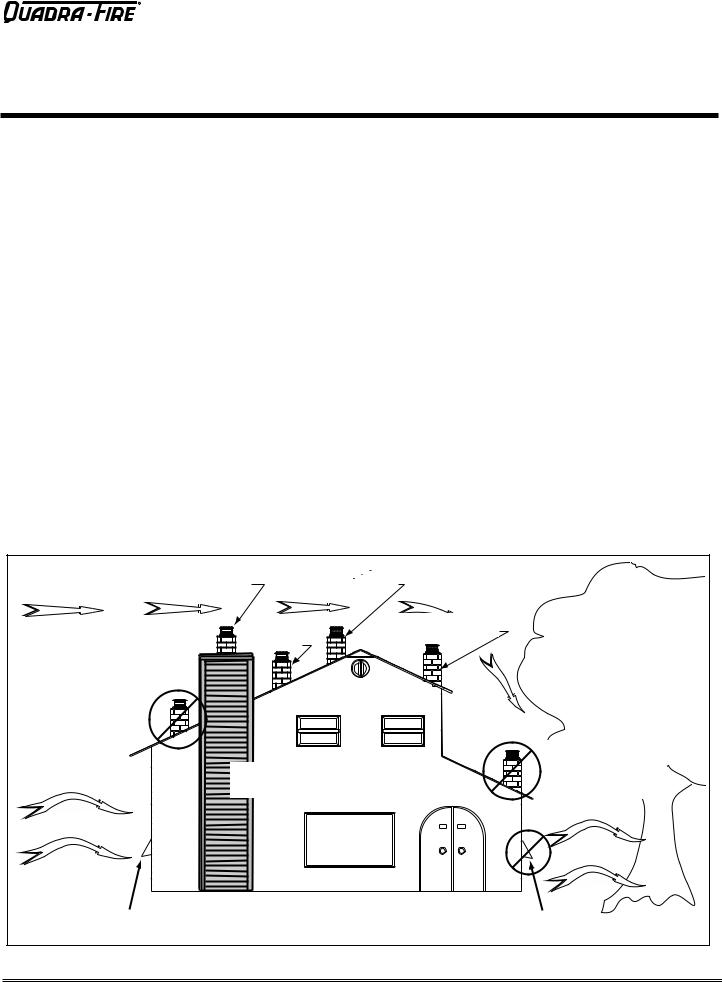
A.Design, Installation & Location Considerations
1. Appliance Location
NOTICE: Check building codes prior to installation.
•Installation MUST comply with local, regional, state and national codes and regulations.
•Consult insurance carrier, local building inspector, fire officials or authorities having jurisdiction over restrictions, installation inspection and permits.
It is a good idea to plan your installation on paper, using exact measurements for clearances and floor protection, before actually beginning the installation
Consideration must be given to:
•Safety, convenience, traffic flow
•Placement of the chimney and chimney connector.
•If you are not using an existing chimney, place the appliance where there will be a clear passage for a factorybuilt listed chimney through the ceiling and roof.
•Installing an optional outside air kit would affect the location of the vent termination.
Since pellet exhaust can contain ash, soot or sparks, you must consider the location of:
•Windows
•Air Intakes
•Air Conditioner
•Overhang, soffits, porch roofs, adjacent walls
•Landscaping, vegetation
When locating vent and venting termination, vent above roof line when possible.
Warning! Risk of Fire Damaged parts could impair safe operation.DoNOTinstalldamaged,incompleteorsubstitute components.
CAUTION! If burning shelled field corn, you must use approved venting specifically designed for corn to prevent corrosion or degradation. Follow the instructions from the venting manufacturer.
NOTICE: Locating the appliance in a location of considerable air movement can cause intermittent smoke spillage from appliance. Do not locate appliance near:
•Frequently open doors
•Central heat outlets or returns
|
|
Recommended Location: |
|
|
|
|
Recommended Location: |
• Above peak |
|
|
|
|
• Above peak |
• Inside heated space |
|
|
|
|
|
|
Marginal Location: |
|
|
|
Marginal Location: |
• |
Wind loading possible |
|
|
|
• Below peak |
|
|
|
|
Location NOT recommended: |
|
|
|
|
|
• |
Not the highest point of the roof |
|
|
|
|
• |
Wind loading possible |
|
|
|
|
|
|
|
|
Location NOT recommended: |
|
|
|
|
|
• |
Too close to tree |
|
Recommended: |
|
|
• |
Below adjacent structure |
|
• Insulated exterior chase |
|
• |
Lower roof line |
|
|
in cooler climates |
|
• |
Avoid outside wall |
|
|
Windward |
|
|
|
|
|
|
|
|
|
Leeward |
|
Recommended: |
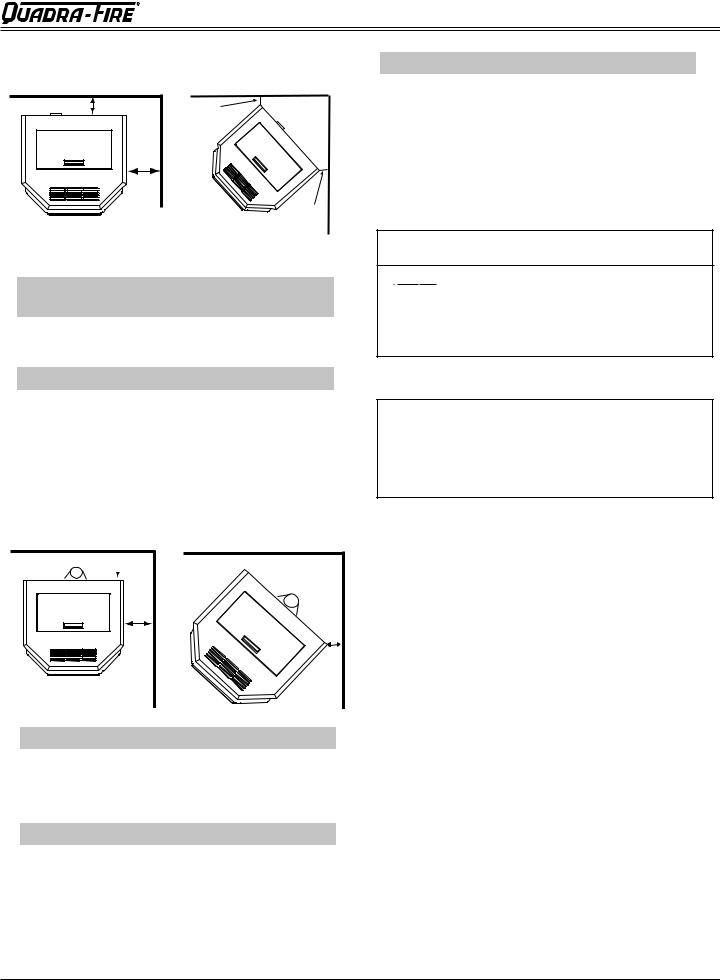
Multi-level Roofs |
|
NOT recommended: |
|
|
|
|
|||
|
Outside Air Intake |
|
|
Outside Air Intake |
|
|
on windward side |
|
|
on leeward side |
|
Figure 5.1 |
|
|
|
|
|
December 16, 2011 |
7014-179D |
|
Page 5 |
||
CB 1200 Pellet Stove
R
B. Locating Your Appliance & Chimney
Location of the appliance and chimney will affect performance.
•Install through the warm airspace enclosed by the building envelope. This helps to produce more draft, especially during lighting and die-down of the fire.
•Penetrate the highest part of the roof. This minimizes the effects of wind loading.
•Locate termination cap away from trees, adjacent structures, uneven roof lines and other obstructions.
•Minimize the use of chimney offsets.
•Consider the appliance location relative to floor and ceiling and attic joists.
•Take into consideration the termination requirements on
Page 11.
 CAUTION
•DO NOT CONNECT THIS UNIT TO A CHIMNEY FLUE SERVICING ANOTHER APPLIANCE.
•DO NOT CONNECT TO ANY AIR DISTRIBUTON DUCT OR SYSTEM.
•May allow flue gases to enter the house.
E. Negative Pressure
WARNING! Risk of Asphyxiation! Negative pressure can cause spillage of combustion fumes and soot.
Negative pressure results from the imbalance of air available for the appliance to operate properly. It can be strongest in lower levels of the house.
Causes include:
•Exhaust fans (kitchen, bath, etc.)
•Range hoods
•Combustion air requirements for furnaces, water heaters and other combustion appliances
•Clothes dryers
•Location of return-air vents to furnace or air conditioning
•Imbalances of the HVAC air handling system
•Upper level air leaks such as:
-Recessed lighting
-Attic hatch
-Duct leaks
To minimize the effects of negative air pressure:
•Install the outside air kit with the intake facing prevailing winds during the heating season
C. Thermostat Location
The thermostat’s location will have some effect on the appliance’s operation. When the thermostat is located close to the appliance, it may require a slightly higher temperature setting to keep the rest of the house comfortable. If the thermostat location is in an adjacent room or on a different floor level, you will notice higher temperatures near the appliance.
D. Draft
Draft is the pressure difference needed to vent appliances successfully. When an appliance is drafting successfully, all combustion byproducts are exiting the home through the chimney.
Considerations for successful draft include:
•Preventing negative pressure
•Location of appliance and chimney
NOTICE: Hearth & Home Technologies assumes no responsibility for the improper performance of the chimney system caused by:
•Inadequate draft due to environmental conditions
•Downdrafts
•Tight sealing construction of the structure
•Mechanical exhausting devices
•Ensure adequate outdoor air for all combustion appliances and exhaust equipment
•Ensure furnace and air conditioning return vents are not located in the immediate vicinity of the appliance
•Avoid installing the appliance near doors, walkways or small isolated spaces
•Recessed lighting should be a “sealed can” design
•Attic hatches weather stripped or sealed
•Attic mounted duct work and air handler joints and seams taped or sealed
 WARNING
Fire Hazard.
•Do not operate appliance before reading and understanding operating instructions.
Failure to operate appliance properly may cause a house fire.
Page 6 |
7014-179D |
December 16, 2011 |

R
CB 1200 Pellet Stove
F. Fire Safety
To provide reasonable fire safety, the following should be given serious consideration:
•Install at least one smoke detector on each floor of your home.
•Locate smoke detector away from the heating appliance and close to the sleeping areas.
•Follow the smoke detector manufacturer’s placement and installation instructions and maintain regularly.
•Conveniently locate a Class A fire extinguisher to contend with small fires.
•In the event of a hopper fire:
•Evacute the house immediately.
•Notify fire department.
G. Tools And Supplies Needed
Tools and building supplies normally required for installation, unless installing into an existing masonry fireplace:
Reciprocating Saw |
Safety Glasses |
Channel Locks |
Framing Square |
Hammer |
Electric Drill & Bits (1/4”) |
Phillips Screwdriver |
1/4” Self-Tapping Screws |
Tape Meausre |
May also need: |
Plumb Line |
|
Level |
Vent Support Straps |
Framing Material |
Venting Paint |
Hi-temp Caulking Material |
|
Gloves |
|
 WARNING
Inspect appliance and components for damage. Damaged parts may impair safe operation.
•Do NOT install damaged components.
•Do NOT install incomplete components.
•Do NOT install substitute components.
Report damaged parts to dealer.
 WARNING
Fire Risk.
Hearth & Home Technologies disclaims any responsibility for, and the warranty will be voided by, the following actions:
•Installation and use of any damaged appliance.
•Modification of the appliance.
•Installation other than as instructed by Hearth & Home Technologies.
•Installation and/or use of any component part not approved by Hearth & Home Technologies.
•Operating appliance without fully assembling all components.
•Operating appliance without legs attached (if supplied with unit).
•Do NOT Overfire
Or any such action that may cause a fire hazard.
H. Inspect Appliance & Components and
Pre-Burn Check List
1. |
|
Place the appliance in a location near the |
|
|
final installation area and follow the proce- |
|
|
dures below: |
2. |
|
Open the appliance and remove all the parts |
|
|
and articles packed inside the Component |
|
|
Pack. Inspect all the parts and glass for ship- |
|
|
ping damage. Contact your dealer if any irregu- |
|
|
larities are noticed. |
3. |
|
All safety warnings have been read and fol- |
|
|
lowed. |
4. |
|
This Owner’s Manual has been read. |
5. |
|
Floor protection requirements have been met. |
6. |
|
Venting is properly installed. |
7. |
|
The proper clearances from the appliance and |
|
|
chimney to combustible materials have been |
|
|
met. |
8. |
|
The masonry chimney is inspected by a profes- |
|
|
sional and is clean, or the factory built metal |
|
|
chimney is installed according to the manufac- |
|
|
turer’s instructions and clearances. |
9. |
|
The chimney meets the required minimum |
|
|
height. |
10. |
|
All labels have been removed from the glass |
|
|
door. |
11. |
|
Plated surfaces have been wiped clean, if |
|
|
applicable. |
12. |
|
Thermostat or remote has been installed. |
13. |
|
A power outlet is available nearby. |
December 16, 2011 |
7014-179D |
Page 7 |

CB 1200 Pellet Stove
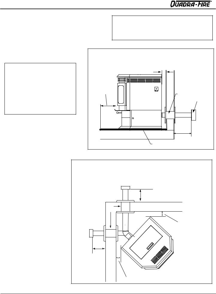
3Dimensions and Clearances
A. Appliance Dimensions
R
8-1/6 in. |
20- 7/16 in. |
|
(205mm) |
(519mm) |
|
|
C |
|
|
L |
|
27-5/8 in. |
25-3/4 in. |
|
(654mm) |
||
(692mm) |
||
|
||
28-1/2 in. (724mm) |
||
4-5/8 in |
|
|
|
(118mm) |
12-3/8 in |
|
|
|
|
||
|
(314mm) |
14-1/4 in |
|
|
|
(362mm) |
|
5.0 in |
C |
2-1/2 in |
|
(127mm) |
|||
L |
(64mm) |
||
|
|
Figure 8.1 - Top View |
Figure 8.2 - Top View with Top Vent Adapter |
|
25-3/4 in. |
|
|
(629mm) |
|
|
C |
|
10-3/4 in. |
L |
|
8-1/16 in. |
||
(273mm) |
||
(205mm) |
||
|
24-3/4 in. |
|
|
(629mm) |
28-1/2 in. 
 (724mm)

31-5/8 in. (803mm)
26-1/2 in. (673mm)
Figure 8.3 - Side View |
Figure 8.4 - Front View |
Page 8 |
7014-179D |
December 16, 2011 |
R
CB 1200 Pellet Stove
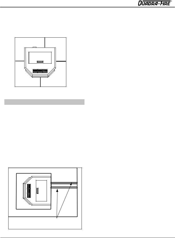
B. Clearances to Combustibles (UL and ULC)
A |
C |
|
B |
|
C |
Straight Back Against |
Inches |
Millimeters |
||
Wall |
|
|
|
|
A |
|
Back Wall to Appliance |
2 |
51 |
B |
|
Side Wall to Appliance |
6 |
152 |
|
|
|
||
Corner Installation |
Inches |
Millimeters |
||
C |
|
Walls to Appliance |
2 |
51 |
Installations with:
3 to 3 inch Top Vent Adapter and
3 to 6 inch Offset Adapter Kit
D
 F G
F G
E
G
Vertical Installation |
Inches |
Millimeters |
|
D |
Back Wall to Flue Pipe |
3 |
76 |
E |
Side Wall to Top |
6 |
152 |
F |
Back Wall to Appliance |
7.5 |
191 |
|
|
|
|
Corner Installation |
Inches |
Millimeters |
|
G |
Walls to Appliance |
2 |
51 |
Alcove Installation |
Inches |
Millimeters |
Minimum Alcove Height |
44 |
1117 |
Minimum Alcove Width |
40-1/2 |
1029 |
Maximum Alcove Depth |
36 |
915 |
Minimum Alcove Side Wall |
6 |
152 |
Top of Unit to Combustibles |
12-1/2 |
318 |
 WARNING
Fire Risk.
Comply with all minimum clearances to combustibles as specified.
Failure to comply may cause house fire.
NOTE:
•Illustrations reflect typical installations and are FOR DESIGN PURPOSES ONLY.
•Illustrations/diagrams are not drawn to scale.
•Actual installation may vary due to individual design preference.
December 16, 2011 |
7014-179D |
Page 9 |
CB 1200 Pellet Stove
C. Hearth Pad Requirements (UL and ULC)
Use a non-combustible floor protector, extending beneath appliance and to the front, sides and rear as indicated. Measure front distance “M” from the surface of the glass door.
|
L* |
K |
K |
|
M |
Figure 10.1 |
|
Hearth Pad Requirements |
Inches |
Millimeters |
|
K |
Sides |
2 |
51 |
L* |
Back |
2 |
51 |
M |
Front |
6 |
152 |
*L Exception for Horizontal Installations:
USA INSTALLATIONS: A non-combustible floor protection is recommended extending beneath the flue pipe when installed with horizontal venting or under the top vent adapter with vertical installation.
CANADA INSTALLATIONS: A non-combustible floor protection extending beneath the flue pipe is required with horizontal venting or under the top vent adapter with vertical installation.
R
Must extend 2 inches (51mm) beyond each side of pipe (shaded area)
Figure 10.2
Page 10 |
7014-179D |
December 16, 2011 |


 R CB 1200 Pellet Stove
4Vent Information
A.Chimney and Exhaust Connection
1.Chimney & Connector: Use 3 or 4 inch (76-102mm) diameter type "L" or "PL" venting system. It can be vented vertically or horizontally.
2.Mobile Home: Approved for all Listed pellet vent. If using the 3 inch (76mm) vertical top vent adapter kit or the 3 to 6 inch (76-152mm) top vent offset adapter, use Listed double wall flue connector. A Quadra-Fire outside air kit must be used with manufactured home installations.
B. Venting Termination Requirements
CAUTION
Do not terminate vent in any enclosed or semi-enclosed area such as a carport, garage, attic, crawl space, under a sun deck or porch, narrow walkway or closely fenced area, or any location that can build up a concentration of fumes such as a stairwell, covered breezeway, etc.
3.Residential: The 3 inch (76mm) vertical top vent adapter kit and the 3 to 6 inch (76-152mm) top vent offset adapter are tested to use 24 gauge single wall flue connector or Listed double wall flue connector to Class A Listed metal chimneys, or masonry chimneys meeting national and/or local codes for solid fuel appliances.
4.INSTALL VENT AT CLEARANCES SPECIFIED BY THE VENT MANUFACTURER.
5.Secure exhaust venting system to the appliance with at least 3 screws. Also secure all connector pipe joints with at least 3 screws through each joint.
6.DO NOT INSTALL A FLUE DAMPER IN THE EXHAUST VENTING SYSTEM OF THIS UNIT.
7.DO NOT CONNECT THIS UNIT TO A CHIMNEY FLUE SERVING ANOTHER APPLIANCE.
NOTE: All pipe must be welded seam pipe whenever possible. Seal pipe joints with high temperature silicone (500°F [260°C] minimum rated only). Do not put silicone inside of pipe.
NOTE: If burning shelled field corn, you must use approved venting specifically designed for corn. Follow the instructions from the venting manufacturer.
 WARNING
Fire Hazard.
•Only LISTED venting components may be used.
•NO OTHER vent components may be used. Substitute or damaged vent components may impair safe operation.
 WARNING
Vent surfaces get HOT, can cause burns if touched. Noncombustible shielding or guards may be required.
1. Termination must exhaust above air inlet elevation. It is recommended that at least 60 inches (1524mm) of vertical pipe be installed when appliance is vented directly through a wall. This will create a natural draft, which will help prevent the possibility of smoke or odor venting into the home during a power outage. It will also keep exhaust from causing a nuisance or hazard by exposing people or shrubs to high temperatures. The safest and preferred venting method is to extend the vent vertically through the roof.
2. Distance from doors and opening windows, or gravity or ventilation air inlets into building:
a.Not less than 48 inches (1.2m) below;
b.Not less than 48 inches (1.2m) horizontally from;
c.Not less than 12 inches (305mm) above.
3.Distance from permanently closed windows:
a.Not less than 12 inches (305mm) below, horizontally from or above.
4. Distance between bottom of termination and grade should be 12 inches (305mm) minimum. This is conditional upon plants in the area, and nature of grade surface. The grade surface must be a non-combustible material (i.e., rock, dirt). The grade surface must not be lawn. Distance between bottom of termination and public walkway should be 84 inches (2134mm) minimum.
5. Distance to combustible materials must be 24 inches (610mm) minimum. This includes adjacent buildings, fences, protruding parts of the structure, roof overhang, plants and shrubs, etc.
6.Termination Cap Location (Home Electrical Service)
•Side-to-side clearance is to be the same as minimum clearance to vinyl inside corners.
•Clearance of a termination cap below electrical service shall be the same as minimum clearance to vinyl soffits.
•Clearance of a termination cap above electrical service will be 12 inches (305mm) minimum.
•Location of the vent termination must not obstruct or interfere with access to the electrical service.
December 16, 2011 |
7014-179D |
Page 11 |
CB 1200 Pellet Stove
R
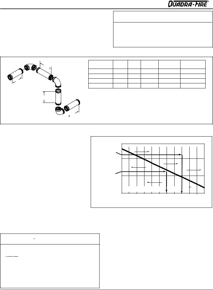
C. Equivalent Feet of Pipe
The table below can help you calculate the equivalent feet of pipe which is a method used to determine pellet vent size.
Figure 12.1.
 WARNING
Improper installation, adjustment, alteration, service or maintenance can cause injury or property damage. Refer to the owner’s information manual provided with this appliance. For assistance or additional information consult a qualified installer, service agency or your dealer.
Example of 3 Elbow-Rear Vent Termination Calculaton
|
2 ft (609mm) |
Pellet Venting |
# of |
Feet of |
Multipled |
Equivalent |
Components |
|
Component |
Elbows |
Pipe |
By |
Feet |
Equivalent Feet |
|
|
|
||||||
|
|
90o Elbow or Tee |
3 |
|
X |
5 |
15 |
|
|
45o Elbow |
|
|
X |
3 |
|
3 ft |
|
Horizontal Pipe |
|
7 |
X |
1 |
7 |
(914mm) |
|
Vertical Pipe |
|
2 |
X |
0.5 |
1 |
2 ft (609mm)

 2 ft (609mm)
Total Equivalent Feet |
23 |
Note: This is a generic example and is not intended to represent any specific fuel type.
Figure 12.1 |
|
|
|
|
|
|
|
|
|
|
|
|
D. Pipe Selection Chart |
|
|
|
|
|
|
|
|
|
|
|
|
The chart will help you in determining proper |
|
30 |
|
4 in. (102mm) Diameter Pipe Only |
|
|||||||
|
|
|
|
|||||||||
venting size according to the equivalent feet of |
Example 1 |
|
|
|
|
|
|
|
|
|
|
|
pipe calculated above and the altitude above sea |
|
20 |
|
|
|
|
|
|
|
|
|
|
level of this installation. Figure 12.2. |
|
|
|
|
|
|
|
|
|
|
||
Equivalent Pipe |
|
|
|
|
|
|
|
|
|
|||
Locate the calculated equivalent feet of pipe on |
Length In Feet |
|
|
|
|
|
|
|
|
|
|
|
|
|
|
|
|
|
|
|
|
|
|
||
the vertical left side of the chart. Move to the |
Example 2 |
10 |
|
|
|
|
|
|
|
|
|
|
right horizontally on the chart until you reach |
|
|
|
|
|
|
|
|
|
|
||
|
|
|
|
|
|
|
|
|
|
|
||
your altitude above sea level. |
|
|
|
|
|
|
|
|
|
|
|
|
If you fall below the diagonal line, 3 or 4 inch (76 |
|
3 in. or 4 in. (76mm or 102mm) Diameter Pipe |
|
|
||||||||
to 102mm) pipe may be used. If it is anywhere |
|
0 |
2 |
3 |
4 |
5 |
6 |
7 |
8 |
9 |
10 |
|
above the diagonal line, a 4 inch (102mm) diam- |
|
1 |
||||||||||
|
|
ALTITUDE IN THOUSANDS OF FEET |
|
|||||||||
eter pipe is required. |
|
|
|
|||||||||
|
|
|
|
|
|
|
|
|
|
|
||
The chart reveals that a 90° elbow is 5 times as |
Figure 12.2 |
Example 1: If the equivalent length of pipe is 23 feet |
||||||||||
restrictive to the flow of exhaust gases under |
||||||||||||
|
(7m)with altitude of 8,000 feet (2438m) you must use |
|||||||||||
positive pressure as 1 foot of horizontal pipe, and |
|
|||||||||||
|
4 inch (102mm) diameter type “L” or “PL” vent. |
|||||||||||
a foot of horizontal pipe is twice as restrictive as |
|
|||||||||||
|
Example 2: If the equivalent length of pipe is 12 feet |
|||||||||||
a foot of vertical pipe. |
|
|||||||||||
|
|
(3.7m) with altitude of 6,000 feet (1829m) you may |
||||||||||
WARNING |
|
use 3 or 4 inch (76 to 102mm) diameter type “L” or |
||||||||||
|
“PL” vent |
|
|
|
|
|
|
|
|
|||
Fire Risk. |
|
|
|
|
|
|
|
|
|
|
|
|
Do NOT pack insulation or other combustibles between firestops.
•ALWAYS maintain specified clearances around venting and firestop systems.
•Install firestops as specified.
Failure to keep insulation or other material away from vent pipe may cause fire.
Page 12 |
7014-179D |
December 16, 2011 |
|
R |
CB 1200 Pellet Stove |
|
|
|
|
|
|
|
|
|
5 |
Venting Systems |
|
|
|
|
|
|
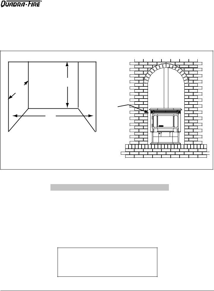
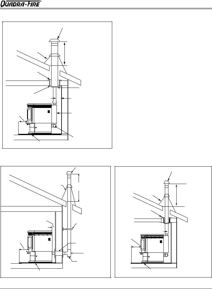
A. Alcove |
|
|
|
A |
C |
D |
B |
Figure 13.1
|
Alcove Installation |
Inches |
Millimeters |
A |
Minimum Alcove Height |
44 |
1117 |
B |
Minimum Alcove Width |
40-1/2 |
1029 |
C |
Maximum Alcove Depth |
36 |
915 |
D |
Minimum Alcove Side Wall |
6 |
152 |
not shown |
Top of Unit to Combustibles |
12-1/2 |
318 |
All minimums listed are to a combustible surface.
NOTE:
•Illustrations reflect typical installations and are FOR DESIGN PURPOSES ONLY.
•Illustrations/diagrams are not drawn to scale.
•Actual installation may vary due to individual design preference.
December 16, 2011 |
7014-179D |
Page 13 |
CB 1200 Pellet Stove
R
B. Through The Wall
Horizontal termination cap must be a minimum of 12 inches. (305mm) from the wall. Approved for mobile home installations. Must use 3 or 4 inch (76-102mm) “L” or “PL” listed pellet venting or listed double wall pipe and a Quadra-Fire outside air kit in mobile homes.
NOTE:
In Canada, where passage through a wall or partition of combustible construction is desired, the installation shall conform to CAN/CSA-B365
NOTICE:
Please note that while the minimum clearance for the termination cap is 6 inches (152mm) there is the possibly of soot buildup around the termination area. If this occurs we suggest to move the termination further away from the house to prevent it.
Straight Out |
2 in. |
|
|
|
(51mm) |
|
|
|
Minimum |
|
|
6 in. |
|
|
|
(152mm) |
|
|
|
Minimum |
|
Horizontal |
|
From Glass |
|
||
Wall |
Termination |
||
|
|||
|
Thimble |
Cap |
|
|
6 in. |
|
|
|
(152mm) |
|
|
|
Minimum |
|
|
|
Non-combustible Hearth Pad |
|
Figure 14.1
45 Degree
Illustration shows venting going in both directions. Choose which one is best for your installation.
6 in. (152mm)
Minimum
Wall
Thimble
2 in. (51mm)
Minimum
6 in.
(152mm) Minimum
2 in. (51mm) Minimum
Figure 14.2
Page 14 |
7014-179D |
December 16, 2011 |
R
CB 1200 Pellet Stove
C. Vertical into Existing Class A Chimney
Rain Cap
Flashing |
24 in. (610mm) |
|
|
minimum |
|
Firestop |
|
|
|
Class A Chimney |
|
Ceiling Support |
Connector Adapter |
|
3 in. (76mm) |
||
|
||
6 in. |
Min. |
|
|
||
(152mm) |
Top Vent Kit |
|
Min. |
||
|
||
|
Clean-out |
|
Non-combustible Hearth Pad |
Cover |
|
|
We recommend a minimum of 60 in. (1.5m) vertical, however above the eave is preferred.
Both installations are approved for mobile home installations. Must use 3 or 4 inch (76 to 102mm) “L” or “PL” Listed pellet venting or listed double wall pipe and Quadra-Fire outside air kit in mobile homes. Single wall pipe is approved for residential installations only.
Figure 15.1
D. Through The Wall & Vertical - External
|
Rain Cap |
Flashing |
24 in. (610mm) |
|
Minimum |
2 in. (51mm) Minimum |
Support Bracket |
|
|
|
every 60 in. (1524mm) |
6 in. (152mm) |
|
Minimum |
Wall Thimble |
|
|
|
Tee |
|
Clean-out Cover |
Non-combustible Hearth Pad |
|
Figure 15.2
E. Vertical - Internal - Typical Installation
Rain Cap
Flashing
Firestop
6 in. (152mm) Min.
24 in. (610mm) Minimum
 3 in. (76mm) Min.
 3 in. to 3 in. (76-76mm) Top Vent Kit
 Clean-out Cover
Non-combustible Hearth Pad
Figure 15.3
December 16, 2011 |
7014-179D |
Page 15 |
 Loading...