


NorthAmerica’sBest
INSTALLATION, OPERATION, AND MAINTENANCE INSTRUCTIONS
QUADRA-FIRE 3100 SERIES
CONGRATULATIONS—You are now the proud owner of one of the finest stoves in the world for your home —the QUADRA-FIRE. Now, before installing your stove and building your first fire—record the serial number on the warranty card. Serial number is located on the safety label on the rear of the stove.
PLEASE READ ALL OF THE OWNERS MANUAL AND SAFETY NOTES
IMPORTANT SAFETY NOTES:
1.When installing your stove, particular attention should be paid to fire protection. If this unit is not properly installed, a house fire may result. For your safety, follow the installation instructions and contact local building or fire officials about restrictions and installation inspection requirements in your area.
2.Never use gasoline or similar liquids to start a fire in this unit. Keep all such liquids well away from stove.
3.During operation, if any part of the stove starts to glow, the stove is in an overfired condition. Close the air controls completely until the glowing has stopped. OVERFIRING VOIDS WARRANTY.
4.Cool ashes should be disposed of carefully, using a metal container.
5.Do not burn wet or green wood. Store wood in dry location.
6.Do not burn garbage, treated wood, or wood with salt (driftwood, etc.). Burning materials other than wood (including charcoal) under adverse conditions may generate carbon monoxide in the home, resulting in illness or possible death.
7.Do not permit creosote or soot to accumulate excessively in the chimney or inside the firebox.
8.Check your chimney system thoroughly when installing into an existing metal or masonry chimney. Seek professional advice if in doubt about its condition.
9.Do not connect this unit to a chimney flue already serving another appliance.
10.Comply with all minimum clearances to combustibles as shown in this manual for this appliance.
11.Build fire on brick firebox floor. Do not use grates, andirons or other method to support fuel.
12.HOT WHILE IN OPERATION. Keep children, pets, clothing and furniture away. Contact can cause skin burns.
13.Do not connect to any air distribution duct or system.
14.RISK OF FIRE! Do not operate with stove door or ash removal system door open.
15.For further information refer to NFPA 211 (U.S.) or CAN/CSA-B365 (Canada).
16.WARNING: WHEN ASSEMBLING A UNIBODY APPLIANCE, USE ONLY GENUINE ALADDIN HEARTH PRODUCTS MANUFACTURED COMPONENTS. USE OF ANY OTHER COMPONENTS WILL VOID YOUR WARRANTY, AND COULD PRESENT A SERIOUS SAFETY HAZARD.
17.WARNING: DO NOT OPERATE YOUR QUADRA-FIRE STOVE BEFORE FULLY ASSEMBLING ALL COMPONENTS. BURNING YOUR STOVE WITHOUT A PEDESTAL OR LEG KIT ATTACHED WILL VOID
YOUR WARRANTY, AND COULD PRESENT A SERIOUS SAFETY HAZARD. |
(Revised 01/1999) |
|||||||||||||||||||||
|
|
|
|
|
|
|
|
|
|
|
|
|
|
|
|
|
|
|
|
|
|
|
|
|
|
|
|
|
|
|
|
|
|
|
|
|
|
|
|
|
|
|
|
|
|
|
|
|
|
|
|
|
|
|
|
|
|
|
|
|
|
|
|
|
|
|
|
|
401 N. WYNNE COLVILLE, WA 99114
SAVE THESE INSTRUCTIONS
www.aladdinhearth.com
aladdin@aladdinhearth.com Part #250-3500 #832-3050
TABLE OF CONTENTS |
|
Safety label ......................................................................................................................................... |
3 |
Dimensions ......................................................................................................................................... |
4 |
Clearances to combustibles ................................................................................................................ |
6 |
Safety listing ....................................................................................................................................... |
7 |
Installation materials needed .............................................................................................................. |
7 |
Venting system ................................................................................................................................... |
7 |
Chimney connector ............................................................................................................................ |
8 |
Chimney height/draft .......................................................................................................................... |
8 |
Connection to a masonry chimney ..................................................................................................... |
8 |
1. Chimney .................................................................................................................................. |
8 |
2. Thimble ................................................................................................................................... |
11 |
A. Brick chimney thimble assembly ..................................................................................... |
11 |
B. 6" solid pack chimney with metal supports ...................................................................... |
12 |
Connection to a metal prefabricated chimney .................................................................................... |
14 |
Mobile home installation .................................................................................................................... |
15 |
Outside air kit installation .................................................................................................................. |
16 |
Pedestal and leg installation ............................................................................................................... |
17 |
Ash removal system installation ........................................................................................................ |
18 |
Ash removal system operating and cleaning ...................................................................................... |
19 |
Operating instructions ........................................................................................................................ |
20 |
Burning process .......................................................................................................................... |
20 |
Primary and secondary air systems ............................................................................................. |
20 |
Blower operating instructions ..................................................................................................... |
21 |
Operating tips .............................................................................................................................. |
21 |
Burning guidelines ...................................................................................................................... |
21 |
Building a fire ............................................................................................................................. |
22 |
Wood selection and storage ........................................................................................................ |
22 |
Maintenance ....................................................................................................................................... |
23 |
Creosote ...................................................................................................................................... |
23 |
Care and cleaning of glass and plated surfaces ........................................................................... |
23 |
Chimney cleaning ....................................................................................................................... |
23 |
Ash removal ................................................................................................................................ |
23 |
Firebrick ...................................................................................................................................... |
23 |
Overfiring .................................................................................................................................... |
23 |
Door handle assembly and glass replacement .................................................................................... |
24 |
Baffle removal and installation .......................................................................................................... |
25 |
Brick pattern ....................................................................................................................................... |
26 |
Installation of optional blower ........................................................................................................... |
27 |
Top heat shield installation ................................................................................................................ |
28 |
Accessories and service parts ............................................................................................................. |
29 |
Notes ............................................................................................................................................... |
30 |
Warranty ............................................................................................................................................. |
31 |
Warranty card ..................................................................................................................................... |
Insert |
Page 2

3100 SAFETY LABEL (found on back of stove)
Model: |
Serial No. |
Quadra-Fire
3100
Manufactaured by:
Page 3
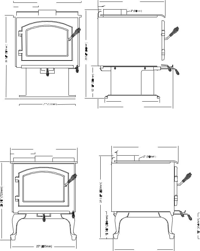
DIMENSIONS
PEDESTAL MODEL
24 1/2" (622m m) |
9" (229m m ) |
23" (584m m ) |
2 1/4" (57m m ) |
20 1/2" (521m m) |
26 3/8" (670m m) |
FIGURE 1a
LEG MODEL
24 1/2" (622m m ) |
9" (229m m ) |
23" (584m m ) |
2 1/4" (57m m ) |
21 1/2" (546m m )
FIGURE 1b
Page 4
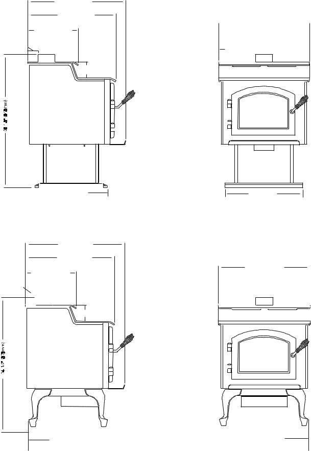
DIMENSIONS
STEP TOP PEDESTAL MODEL
26 5/8" (676m m )
23 7/8" (606m m )
13 11/16" (348m m )
2 13/16" (72m m ) 
4 5/16" (110m m )
 20 1/2" (521m m )
 24 5/8" (626m m )
9" (229m m ) 

FIGURE 2a
21" (533m m )
STEP TOP LEG MODEL
26 5/8" (676m m )
23 7/8" (606m m )
24 5/8" (626m m )
13 11/16" (348m m )
2 13/16" (72m m ) |
|
9" (229m m ) |
|
|
|
|||||||
|
|
|
||||||||||
|
|
|
|
|
|
|
|
|
|
|
|
|
|
|
|
|
|
|
|
|
|
|
|
|
|
|
|
|
|
|
|
|
|
|
|
|
|
|
|
|
|
|
|
|
|
|
|
|
|
|
|
|
|
|
|
|
|
|
|
|
|
|
|
|
|
|
|
|
|
|
|
|
|
|
|
|
|
4 5/16" (110m m )
21 1/2 (546m m ) |
|
FIGURE 2b |
|
25" (635m m ) |
|
|
|||
|
|
|
||
|
|
|
|
|
|
|
|
|
|
Page 5
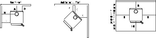
CLEARANCES TO COMBUSTIBLES (UL AND ULC)
FLOOR PROTECTION: Floor protector must be noncombustible material or equivalent, extending beneath heater and to the front/ sides/rear as indicated.
NOTE: A 3/8” (10mm) minimum thickness tile or equivalent is recommended, but not required.
Minimum clearances to Combustible Materials (in inches and millimeters) for Quadra-Fire 3100 Standard Stove
|
|
Chimney & |
|
|
|
|
|
|
Installation |
Clearance |
Connector |
A |
B |
C |
D |
E |
F |
Residential |
Standard |
Note 1 |
14”(356) |
26”(661) |
18”(457) |
12”(305) |
18”(457) |
10”(254) |
Residential/Mobile Home |
Reduced |
Note 2 |
12”(305) |
26”(661) |
16”(406) |
10”(254) |
18”(457) |
8”(203) |
Alcove |
Standard |
Note 2 & 3 |
12”(305) |
26”(661) |
N/A |
10”(254) |
18”(457) |
8”(203) |
Minimum clearances to Combustible Materials (in inches and millimeters) for Quadra-Fire 3100 with top shield |
|
|||||||
|
|
Chimney & |
|
|
|
|
|
|
Installation |
Clearance |
Connector |
A |
B |
C |
D |
E |
F |
Residential |
Standard |
Note 1 |
12”(305) |
24”(610) |
16”(406) |
10”(254) |
16”(406) |
8”(203) |
Residential/Mobile Home |
Reduced |
Note 2 |
10”(254) |
24”(610) |
14”(356) |
8”(203) |
16”(406) |
6”(153) |
Alcove |
Standard |
Note 2 & 3 |
10”(254) |
24”(610) |
N/A |
8”(203) |
16”(406) |
6”(153) |
Minimum clearances to Combustible Materials (in inches and millimeters) for Quadra-Fire 3100 Step Top Stove |
|
|||||||
|
|
Chimney & |
|
|
|
|
|
|
Installation |
Clearances |
Connector |
A |
B |
C |
D |
E |
F |
Residential |
Standard |
Note 1 |
12”(305) |
24”(610) |
16”(406) |
10”(254) |
16”(406) |
8”(203) |
Residential/Mobile Home |
Reduced |
Note 2 |
10”(254) |
24”(610) |
14”(356) |
8”(203) |
16”(406) |
6”(153) |
Alcove |
Standard |
Note 2 & 3 |
10”(254) |
24”(610) |
N/A |
8”(203) |
16”(406) |
6”(153) |
Note 1: 6” (152mm) diameter single wall, minimum 24 MSG black or blued steel connector pipe with a listed factory-built type HT chimney suitable for use with solid fuels or a masonry chimney.
Note 2: 6” (152mm) diameter double wall insulated connector pipe with listed factory-built type HT chimney or a masonry chimney. (Mobile home venting system must be equipped with a rain cap and spark arrestor.) For installations with a preexisting class A chimney system, a listed stainless steel chimney liner should be installed, or the existing chimney examined by a chimney sweep for acceptable further use.
Note 3: Alcove specifications: Maximum depth of alcove shall be no more than 48” (1219mm). For additional alcove information and clearances, refer to clearances to combustibles above.
NOTE: Unit is approved for use with listed double wall air-insulated chimney connector or elbows.
When locating your stove consider safety, convenience, traffic flow, and the fact that the stove will need a chimney and chimney connector.
FLOOR PROTECTION: Floor protector must be noncombustible material, extending beneath heater and to the front/sides/rear as indicated.
NOTE: A 3/8” (10mm) minimum thickness tile or equivalent is recommended, but not required.
NFPA 211: Use a noncombustible material with 1” (25mm) ventilated air space to reduce clearances. However, this is not to exceed 50% of Quadra-Fire’s specified clearances.
NOTE: Must follow NFPA 211 spacing and materials to qualify. It is also subject to local jurisdiction.
AVOID FIRE: Maintain the designated clearances to combustibles. Insulation must not touch the chimney. You must maintain the designated air space clearance around the chimney. This space around a chimney is necessary to allow natural heat removal from the area. Insulation in this space will cause a heat buildup, which may ignite wood framing.
Page 6
SAFETY LISTING
The Quadra-Fire 3100 is listed by OMNI-Test Laboratories, Inc. , Beaverton, Oregon, to UL 1482-83, (UM)84 HUD and ULC S627. It is also approved for mobile home installations with outside combustion air in the U.S. (see pages 15 and 16 for further details). For residential installations in Canada without an outside combustion air kit, a source of fresh air into the room must be provided.
INSTALLATION MATERIALS NEEDED FOR YOUR SAFETY
CHIMNEY CONNECTOR (also known as flue pipe or stove pipe): The chimney connector joins the stove to the chimney (see page 8). It should be 6” (152mm) minimum diameter 24 MSG black or blued steel, or an approved air-insulated double wall venting pipe.
THIMBLE: A manufactured or site-constructed device installed in combustible walls through which the chimney connector passes to the chimney (see page 11-13). It is intended to keep the walls from igniting.
CHIMNEY SYSTEMS:
A.APPROVED MASONRY (see specifications on pages 8-13) with at least 5/8” (16mm) fire clay lining joined with refractory cement or other listed system suitable for use with wood stoves.
B.PREFABRICATED 6" (152mm) listed high temperature (UL 103HT or ULC 629M) chimney. Components required by manufacturers for installation such as the chimney support base, firestop (as appropriate), attic insulation shield, insulated tee, etc., are necessary to assure a safe chimney installation. Use only components manufactured for the chimney. Chimney installation should meet NFPA 211 standards.
FIRE SAFETY: To provide reasonable fire safety, the following should be given serious consideration:
1.Install at least one smoke detector on each floor of your home to ensure your safety. They should be located away from the heating appliance and close to the sleeping areas. Follow the smoke detector manufacturer’s placement and installation instructions, and be sure to maintain regularly.
2.A conveniently located Class A fire extinguisher to contend with small fires resulting from burning embers.
3.A practiced evacuation plan, consisting of at least two escape routes.
4.A plan to deal with a chimney fire as follows: In the event of a chimney fire:
A.Notify fire department
B.Prepare occupants for immediate evacuation.
C.Close all openings into the stove.
D.While awaiting fire department, watch for ignition of adjacent combustibles from overheated stove pipe, hot embers or sparks from the chimney.
VENTING SYSTEM
The venting system consists of a chimney connector and a chimney. These get extremely hot during use. Temperatures inside the chimney may exceed 2000°F (1100°C) in the event of a creosote fire. To protect against the possibility of a house fire, the chimney connector and chimney must be properly installed and maintained. An approved thimble must be used when a connection is made through a combustible wall to a chimney. A chimney support package must be used when a connection is made through the ceiling to a prefabricated chimney. These accessories are absolutely necessary to provide safe clearances to combustible wall and ceiling material. Follow venting manufacturer’s clearances when installing venting system.
This stove may be connected to a lined masonry chimney or a listed high temperature prefabricated approved metal chimney. Do not connect it to a chimney serving another appliance. To do so will affect the safe operation of both appliances.
Page 7
CHIMNEY CONNECTOR
The chimney connector must be 6” (152mm) diameter with a minimum thickness of 24 gauge. Do not use aluminum or galvanized steel. They cannot properly withstand the extreme temperatures of a wood fire. Do not use chimney connector pipe as a chimney. You must connect your stove to a chimney comparable to those illustrated in this manual.
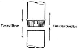
Chimney connector sections must be attached to the stove and to each other with the crimped end toward the stove (Figure 3). This allows creosote to run into the stove and not onto the outside of the pipe. Attach the chimney connector to the flue collar with three sheet metal screws. All joints should also be secured with three sheet metal screws. Otherwise, in the event of a creosote fire, the connector may vibrate apart.
FIGURE 3
For proper operation, the chimney connector should be as short as possible. Horizontal lengths of chimney connector should have a minimum upward slope from the stove of at least ¼” per foot.
CHIMNEY HEIGHT/DRAFT
To insure that your Quadra-Fire stove burns properly, the chimney draft (static pressure) should be approximately 0.1” water column (W.C.) during a high burn and .04” W.C. during a low burn, measured 6” (152mm) above the top of the stove after one hour of operation at each burn setting.
NOTE: These are guidelines only, and may vary somewhat for individual installations.
Your Quadra-Fire stove was designed for and tested on a 6” (152mm) chimney, 12’-14’ (3.66-4.27m) high, measured from the top of the stove. The further your stack height or diameter varies from this configuration, the probability of performance problems increases. In addition, exterior conditions such as roof line, surrounding trees, prevailing winds and nearby hills can influence stove performance.
CONNECTION TO A MASONRY CHIMNEY
1.CHIMNEY: Should the stove be connected to a masonry chimney, the chimney should be examined for cracks, loose mortar, or other signs of deterioration and blockage. The stove should not be installed until it is determined that the chimney is safe for use. Since an oversized flue contributes to the accumulation of creosote, the size of the flue should be checked to determine that it is not too large for the stove. The chimney should also be checked to insure it meets the minimum standards of the National Fire Protection Association (NFPA) Standard 211. Following is a list of the more critical minimum requirements for a properly constructed chimney.
The masonry wall of the chimney, if brick or modular block, must be a minimum of 4” (102mm) thick. A mountain or rubble stone wall must be at least 12” (305mm) thick.
Page 8
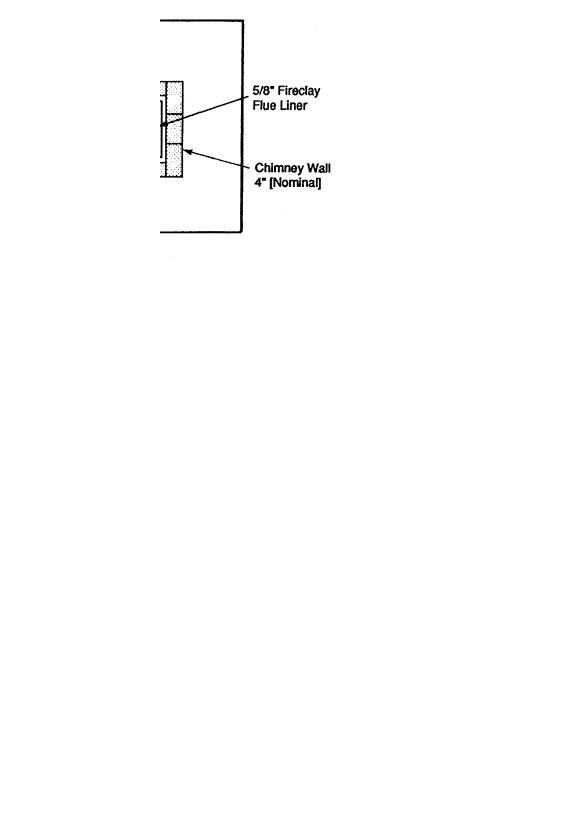
The chimney must have a fire clay flue liner (or equivalent) with a minimum thickness of 5/8” (16mm) and must be installed with refractory mortar. There must be at least ½” (13mm) air space between the flue liner and the chimney wall (Figure 4). An equivalent liner must be a listed chimney liner system or other approved material.
FIGURE 4
A chimney inside the house must have at least 2” (50mm) of clearance to the combustible structure. A chimney outside the house must have at least 1” (25mm) clearance to the combustible structure. Firestops must be installed in the spaces where the chimney passes through floors and/or ceiling (Figure 5).
FIGURE 5
Page 9
Remember that insulation must not contact the chimney. There must be air space around the chimney. Insulation must be 2” (50mm) or more from the chimney (Figure 6).
FIGURE 6
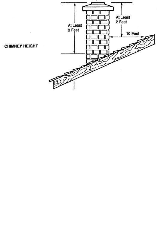
A chimney must be the required height above the roof or other obstruction for safety and proper draft operation. The chimney must be a minimum of 3’ (914mm) higher than the highest point where it passes through the roof, and at least 2’ (610mm) higher than the highest part of the roof or structure that is within 10’ (3048mm) of the chimney, measured horizontally (Figure 7).
FIGURE 7
Page 10
 Loading...