


 Loading...
Configuration manual for QSW-3400
QSW-3400 series
CONFIGURATION MANUAL

Content |
|
CONTENT ........................................................................................................... |
1 |
CHAPTER 1 SWITCH MANAGEMENT............................................................. |
16 |
1.1 MANAGEMENT OPTIONS ................................................................................................ |
16 |
1.1.1 Out-Of-Band Management ............................................................................. |
16 |
1.1.2 In-band Management...................................................................................... |
20 |
1.2 CLI INTERFACE ............................................................................................................. |
26 |
1.2.1 Configuration Modes...................................................................................... |
27 |
1.2.2 Configuration Syntax ..................................................................................... |
29 |
1.2.3 Shortcut Key Support..................................................................................... |
30 |
1.2.4 Help Function.................................................................................................. |
30 |
1.2.5 Input Verification ............................................................................................ |
31 |
1.2.6 Fuzzy Match Support...................................................................................... |
31 |
CHAPTER 2 BASIC SWITCH CONFIGURATION............................................. |
33 |
2.1 BASIC CONFIGURATION ................................................................................................. |
33 |
2.2 TELNET MANAGEMENT .................................................................................................. |
34 |
2.2.1 Telnet ............................................................................................................... |
34 |
2.2.2 SSH .................................................................................................................. |
36 |
2.3 CONFIGURE SWITCH IP ADDRESSES ............................................................................... |
37 |
2.3.1 Switch IP Addresses Configuration Task List.............................................. |
38 |
2.4 SNMP CONFIGURATION................................................................................................. |
39 |
2.4.1 Introduction to SNMP ..................................................................................... |
39 |
2.4.2 Introduction to MIB......................................................................................... |
40 |
2.4.3 Introduction to RMON .................................................................................... |
41 |
2.4.4 SNMP Configuration....................................................................................... |
42 |
2.4.5 Typical SNMP Configuration Examples ........................................................ |
45 |
2.4.6 SNMP Troubleshooting .................................................................................. |
46 |
2.5 SWITCH UPGRADE......................................................................................................... |
47 |
2.5.1 Switch System Files ....................................................................................... |
47 |
2.5.2 BootROM Upgrade.......................................................................................... |
48 |
2.5.3 FTP/TFTP Upgrade ......................................................................................... |
50 |
CHAPTER 3 FILE SYSTEM OPERATIONS ...................................................... |
60 |
3.1 INTRODUCTION TO FILE STORAGE DEVICES ..................................................................... |
60 |
+7(495) 797-3311 www.qtech.ru |
|
Москва, Новозаводская ул., 18, стр. 1 |
|
1

3.2 FILE SYSTEM OPERATION CONFIGURATION TASK LIST...................................................... |
60 |
3.3 TYPICAL APPLICATIONS ................................................................................................. |
62 |
3.4 TROUBLESHOOTING....................................................................................................... |
62 |
CHAPTER 4 CLUSTER CONFIGURATION ...................................................... |
63 |
4.1 INTRODUCTION TO CLUSTER NETWORK MANAGEMENT ...................................................... |
63 |
4.2 CLUSTER NETWORK MANAGEMENT CONFIGURATION SEQUENCE ...................................... |
63 |
4.3 EXAMPLES OF CLUSTER ADMINISTRATION ....................................................................... |
66 |
4.4 CLUSTER ADMINISTRATION TROUBLESHOOTING .............................................................. |
67 |
CHAPTER 5 PORT CONFIGURATION............................................................. |
68 |
5.1 INTRODUCTION TO PORT ................................................................................................ |
68 |
5.2 NETWORK PORT CONFIGURATION TASK LIST .................................................................. |
68 |
5.3 PORT CONFIGURATION EXAMPLE ................................................................................... |
71 |
5.4 PORT TROUBLESHOOTING ............................................................................................. |
72 |
CHAPTER 6 PORT ISOLATION FUNCTION CONFIGURATION...................... |
73 |
6.1 INTRODUCTION TO PORT ISOLATION FUNCTION ................................................................ |
73 |
6.2 TASK SEQUENCE OF PORT ISOLATION............................................................................. |
73 |
6.3 PORT ISOLATION FUNCTION TYPICAL EXAMPLES ............................................................. |
74 |
CHAPTER 7 PORT LOOPBACK DETECTION FUNCTION CONFIGURATION |
|
.......................................................................................................................... |
75 |
7.1 INTRODUCTION TO PORT LOOPBACK DETECTION FUNCTION ............................................. |
75 |
7.2 PORT LOOPBACK DETECTION FUNCTION CONFIGURATION TASK LIST ............................... |
75 |
7.3 PORT LOOPBACK DETECTION FUNCTION EXAMPLE.......................................................... |
77 |
7.4 PORT LOOPBACK DETECTION TROUBLESHOOTING .......................................................... |
78 |
CHAPTER 8 ULDP FUNCTION CONFIGURATION.......................................... |
79 |
8.1 INTRODUCTION TO ULDP FUNCTION ............................................................................... |
79 |
8.2 ULDP CONFIGURATION TASK SEQUENCE ....................................................................... |
80 |
8.3 ULDP FUNCTION TYPICAL EXAMPLES ............................................................................ |
83 |
8.4 ULDP TROUBLESHOOTING ............................................................................................ |
84 |
CHAPTER 9 LLDP FUNCTION OPERATION CONFIGURATION .................... |
86 |
9.1 INTRODUCTION TO LLDP FUNCTION ............................................................................... |
86 |
9.2 LLDP FUNCTION CONFIGURATION TASK SEQUENCE ........................................................ |
87 |
9.3 LLDP FUNCTION TYPICAL EXAMPLE .............................................................................. |
90 |
9.4 LLDP FUNCTION TROUBLESHOOTING............................................................................. |
91 |
+7(495) 797-3311 www.qtech.ru |
|
Москва, Новозаводская ул., 18, стр. 1 |
|
2

CHAPTER 10 PORT CHANNEL CONFIGURATION |
.........................................92 |
10.1 INTRODUCTION TO PORT CHANNEL ............................................................................... |
92 |
10.2 BRIEF INTRODUCTION TO LACP ................................................................................... |
93 |
10.2.1 Static LACP Aggregation ............................................................................. |
94 |
10.2.2 Dynamic LACP Aggregation ........................................................................ |
94 |
10.3 PORT CHANNEL CONFIGURATION TASK LIST ................................................................. |
94 |
10.4 PORT CHANNEL EXAMPLES ......................................................................................... |
96 |
10.5 PORT CHANNEL TROUBLESHOOTING ............................................................................ |
98 |
CHAPTER 11 MTU CONFIGURATION ........................................................... |
100 |
11.1 INTRODUCTION TO MTU ............................................................................................. |
100 |
11.2 MTU CONFIGURATION TASK SEQUENCE ..................................................................... |
100 |
CHAPTER 12 EFM OAM CONFIGURATION .................................................. |
101 |
12.1 INTRODUCTION TO EFM OAM.................................................................................... |
101 |
12.2 EFM OAM CONFIGURATION ...................................................................................... |
104 |
12.3 EFM OAM EXAMPLE ................................................................................................ |
106 |
12.4 EFM OAM TROUBLESHOOTING ................................................................................. |
107 |
CHAPTER 13 PORT SECURITY..................................................................... |
108 |
13.1 INTRODUCTION TO PORT SECURITY........................................................................ |
108 |
13.2 PORT SECURITY CONFIGURATION TASK LIST .......................................................... |
108 |
13.3 EXAMPLE OF PORT SECURITY ............................................................................... |
109 |
13.4 PORT SECURITY TROUBLESHOOTING ..................................................................... |
110 |
CHAPTER 14 DDM CONFIGURATION........................................................... |
111 |
14.1 INTRODUCTION TO DDM ............................................................................................ |
111 |
14.1.1 Brief Introduction to DDM .......................................................................... |
111 |
14.1.2 DDM Function ............................................................................................. |
112 |
14.2 DDM CONFIGURATION TASK LIST............................................................................... |
113 |
14.3 EXAMPLES OF DDM .................................................................................................. |
114 |
14.4 DDM TROUBLESHOOTING.......................................................................................... |
119 |
CHAPTER 15 LLDP-MED ............................................................................... |
120 |
15.1 INTRODUCTION TO LLDP-MED .................................................................................. |
120 |
15.2 LLDP-MED CONFIGURATION TASK SEQUENCE........................................................... |
120 |
15.3 LLDP-MED EXAMPLE .............................................................................................. |
122 |
15.4 LLDP-MED TROUBLESHOOTING ............................................................................... |
125 |
CHAPTER 16 BPDU-TUNNEL CONFIGURATION ......................................... |
126 |
+7(495) 797-3311 www.qtech.ru |
|
Москва, Новозаводская ул., 18, стр. 1 |
|
3

16.1 INTRODUCTION TO BPDU-TUNNEL................................................................................ |
126 |
16.1.1 bpdu-tunnel function.................................................................................. |
126 |
16.1.2 Background of bpdu-tunnel....................................................................... |
126 |
16.2 BPDU-TUNNEL CONFIGURATION TASK LIST .................................................................. |
127 |
16.3 EXAMPLES OF BPDU-TUNNEL...................................................................................... |
127 |
16.4 BPDU-TUNNEL TROUBLESHOOTING ............................................................................. |
129 |
CHAPTER 17 EEE ENERGY-SAVING CONFIGURATION ............................. |
130 |
17.1 INTRODUCTION TO EEE ENERGY-SAVING .................................................................... |
130 |
17.2 EEE ENERGY-SAVING CONFIGURATION LIST ................................................................ |
130 |
17.3 EEE ENERGY-SAVING TYPICAL EXAMPLES.................................................................. |
130 |
CHAPTER 18 VLAN CONFIGURATION ......................................................... |
131 |
18.1 VLAN CONFIGURATION ............................................................................................. |
131 |
18.1.1 Introduction to VLAN.................................................................................. |
131 |
18.1.2 VLAN Configuration Task List ................................................................... |
132 |
18.1.3 Typical VLAN Application .......................................................................... |
135 |
18.1.4 Typical Application of Hybrid Port ............................................................ |
136 |
18.2 DOT1Q-TUNNEL CONFIGURATION................................................................................ |
138 |
18.2.1 Introduction to Dot1q-tunnel ..................................................................... |
138 |
18.2.2 Dot1q-tunnel Configuration ....................................................................... |
140 |
18.2.3 Typical Applications of the Dot1q-tunnel ................................................. |
140 |
18.2.4 Dot1q-tunnel Troubleshooting .................................................................. |
141 |
18.3 SELECTIVE QINQ CONFIGURATION ............................................................................. |
141 |
18.3.1 Introduction to Selective QinQ .................................................................. |
141 |
18.3.2 Selective QinQ Configuration.................................................................... |
142 |
18.3.3 Typical Applications of Selective QinQ..................................................... |
142 |
18.3.4 Selective QinQ Troubleshooting ............................................................... |
144 |
18.4 VLAN-TRANSLATION CONFIGURATION ........................................................................ |
144 |
18.4.1 Introduction to VLAN-translation .............................................................. |
144 |
18.4.2 VLAN-translation Configuration ................................................................ |
145 |
18.4.3 Typical application of VLAN-translation ................................................... |
146 |
18.4.4 VLAN-translation Troubleshooting ........................................................... |
147 |
18.5 MULTI-TO-ONE VLAN TRANSLATION CONFIGURATION ................................................. |
147 |
18.5.1 Introduction to Multi-to-One VLAN Translation ....................................... |
147 |
18.5.2 Multi-to-One VLAN Translation Configuration ......................................... |
147 |
18.5.3 Typical application of Multi-to-One VLAN Translation ............................ |
148 |
18.5.4 Multi-to-One VLAN Translation Troubleshooting..................................... |
149 |
+7(495) 797-3311 www.qtech.ru |
|
Москва, Новозаводская ул., 18, стр. 1 |
|
4

18.6 DYNAMIC VLAN CONFIGURATION............................................................................... |
149 |
18.6.1 Introduction to Dynamic VLAN.................................................................. |
149 |
18.6.2 Dynamic VLAN Configuration ................................................................... |
150 |
18.6.3 Typical Application of the Dynamic VLAN................................................ |
152 |
18.6.4 Dynamic VLAN Troubleshooting ............................................................... |
153 |
18.7 GVRP CONFIGURATION............................................................................................. |
153 |
18.7.1 Introduction to GVRP ................................................................................. |
153 |
18.7.2 GVRP Configuration Task List................................................................... |
154 |
18.7.3 Example of GVRP ....................................................................................... |
155 |
18.7.4 GVRP Troubleshooting .............................................................................. |
157 |
18.8 VOICE VLAN CONFIGURATION ................................................................................... |
157 |
18.8.1 Introduction to Voice VLAN ....................................................................... |
157 |
18.8.2 Voice VLAN Configuration ......................................................................... |
158 |
18.8.3 Typical Applications of the Voice VLAN ................................................... |
158 |
18.8.4 Voice VLAN Troubleshooting .................................................................... |
160 |
CHAPTER 19 MAC TABLE CONFIGURATION .............................................. |
161 |
19.1 INTRODUCTION TO MAC TABLE .................................................................................. |
161 |
19.1.1 Obtaining MAC Table.................................................................................. |
161 |
19.1.2 Forward or Filter ......................................................................................... |
162 |
19.2 MAC ADDRESS TABLE CONFIGURATION TASK LIST ...................................................... |
163 |
19.3 TYPICAL CONFIGURATION EXAMPLES ......................................................................... |
165 |
19.4 MAC TABLE TROUBLESHOOTING ............................................................................... |
165 |
19.5 MAC ADDRESS FUNCTION EXTENSION ....................................................................... |
166 |
19.5.1 MAC Address Binding................................................................................ |
166 |
19.6 MAC NOTIFICATION CONFIGURATION ......................................................................... |
168 |
19.6.1 Introduction to MAC Notification............................................................... |
168 |
19.6.2 MAC Notification Configuration ................................................................ |
168 |
19.6.3 MAC Notification Example ......................................................................... |
170 |
19.6.4 MAC Notification Troubleshooting............................................................ |
170 |
CHAPTER 20 MSTP CONFIGURATION ......................................................... |
171 |
20.1 INTRODUCTION TO MSTP........................................................................................... |
171 |
20.1.1 MSTP Region .............................................................................................. |
171 |
20.1.2 Port Roles.................................................................................................... |
173 |
20.1.3 MSTP Load Balance ................................................................................... |
173 |
20.2 MSTP CONFIGURATION TASK LIST ............................................................................. |
173 |
20.3 MSTP EXAMPLE ....................................................................................................... |
177 |
+7(495) 797-3311 www.qtech.ru |
|
Москва, Новозаводская ул., 18, стр. 1 |
|
5

20.4 MSTP TROUBLESHOOTING ........................................................................................ |
182 |
CHAPTER 21 QOS CONFIGURATION........................................................... |
183 |
21.1 INTRODUCTION TO QOS ............................................................................................. |
183 |
21.1.1 QoS Terms................................................................................................... |
183 |
21.1.2 QoS Implementation................................................................................... |
184 |
21.1.3 Basic QoS Model ........................................................................................ |
185 |
21.2 QOS CONFIGURATION TASK LIST ............................................................................... |
188 |
21.3 QOS EXAMPLE ......................................................................................................... |
193 |
21.4 QOS TROUBLESHOOTING .......................................................................................... |
195 |
CHAPTER 22 FLOW-BASED REDIRECTION ................................................ |
196 |
22.1 INTRODUCTION TO FLOW-BASED REDIRECTION ............................................................ |
196 |
22.2 FLOW-BASED REDIRECTION CONFIGURATION TASK SEQUENCE .................................... |
196 |
22.3 FLOW-BASED REDIRECTION EXAMPLES ...................................................................... |
197 |
22.4 FLOW-BASED REDIRECTION TROUBLESHOOTING HELP ................................................ |
197 |
CHAPTER 23 FLEXIBLE QINQ CONFIGURATION........................................ |
198 |
23.1 INTRODUCTION TO FLEXIBLE QINQ ............................................................................. |
198 |
23.1.1 QinQ Technique .......................................................................................... |
198 |
23.1.2 Basic QinQ .................................................................................................. |
198 |
23.1.3 Flexible QinQ .............................................................................................. |
198 |
23.2 FLEXIBLE QINQ CONFIGURATION TASK LIST ............................................................... |
198 |
23.3 FLEXIBLE QINQ EXAMPLE.......................................................................................... |
200 |
23.4 FLEXIBLE QINQ TROUBLESHOOTING........................................................................... |
202 |
CHAPTER 24 LAYER 3 MANAGEMENT CONFIGURATION ......................... |
203 |
24.1 LAYER 3 MANAGEMENT INTERFACE ............................................................................ |
203 |
24.1.1 Introduction to Layer 3 Management Interface ........................................ |
203 |
24.1.2 Layer 3 Interface Configuration Task List ................................................ |
203 |
24.2 IP CONFIGURATION ................................................................................................... |
204 |
24.2.1 Introduction to IPv4, IPv6........................................................................... |
204 |
24.2.2 IP Configuration.......................................................................................... |
206 |
24.2.3 IPv6 Troubleshooting ................................................................................. |
208 |
24.3 STATIC ROUTE .......................................................................................................... |
208 |
24.3.1 Introduction to Static Route....................................................................... |
208 |
24.3.2 Introduction to Default Route .................................................................... |
208 |
24.3.3 Static Route Configuration Task List ........................................................ |
209 |
24.3.4 Static Route Configuration Examples....................................................... |
209 |
+7(495) 797-3311 www.qtech.ru |
|
Москва, Новозаводская ул., 18, стр. 1 |
|
6

24.4 ARP ........................................................................................................................ |
210 |
24.4.1 Introduction to ARP .................................................................................... |
210 |
24.4.2 ARP Configuration Task List...................................................................... |
210 |
24.4.3 ARP Troubleshooting ................................................................................. |
210 |
CHAPTER 25 ARP SCANNING PREVENTION FUNCTION CONFIGURATION |
|
........................................................................................................................ |
211 |
25.1 INTRODUCTION TO ARP SCANNING PREVENTION FUNCTION ......................................... |
211 |
25.2 ARP SCANNING PREVENTION CONFIGURATION TASK SEQUENCE.................................. |
211 |
25.3 ARP SCANNING PREVENTION TYPICAL EXAMPLES ...................................................... |
213 |
25.4 ARP SCANNING PREVENTION TROUBLESHOOTING HELP.............................................. |
214 |
CHAPTER 26 PREVENT ARP SPOOFING CONFIGURATION ...................... |
215 |
26.1 OVERVIEW ................................................................................................................ |
215 |
26.1.1 ARP (Address Resolution Protocol).......................................................... |
215 |
26.1.2 ARP Spoofing.............................................................................................. |
215 |
26.1.3 How to prevent void ARP Spoofing........................................................... |
215 |
26.2 PREVENT ARP SPOOFING CONFIGURATION ................................................................. |
216 |
26.3 PREVENT ARP SPOOFING EXAMPLE........................................................................... |
217 |
CHAPTER 27 ARP GUARD CONFIGURATION ............................................. |
219 |
27.1 INTRODUCTION TO ARP GUARD ............................................................................... |
219 |
27.2 ARP GUARD CONFIGURATION TASK LIST ................................................................. |
220 |
CHAPTER 28 GRATUITOUS ARP CONFIGURATION ................................... |
221 |
28.1 INTRODUCTION TO GRATUITOUS ARP ......................................................................... |
221 |
28.2 GRATUITOUS ARP CONFIGURATION TASK LIST............................................................ |
221 |
28.3 GRATUITOUS ARP CONFIGURATION EXAMPLE............................................................. |
222 |
28.4 GRATUITOUS ARP TROUBLESHOOTING....................................................................... |
222 |
CHAPTER 29 DHCP CONFIGURATION......................................................... |
224 |
29.1 INTRODUCTION TO DHCP .......................................................................................... |
224 |
29.2 DHCP SERVER CONFIGURATION ................................................................................ |
225 |
29.3 DHCP RELAY CONFIGURATION .................................................................................. |
227 |
29.4 DHCP CONFIGURATION EXAMPLES ............................................................................ |
229 |
29.5 DHCP TROUBLESHOOTING........................................................................................ |
232 |
CHAPTER 30 DHCPV6 CONFIGURATION .................................................... |
234 |
30.1 INTRODUCTION TO DHCPV6 ...................................................................................... |
234 |
30.2 DHCPV6 SERVER CONFIGURATION ............................................................................ |
235 |
+7(495) 797-3311 www.qtech.ru |
|
Москва, Новозаводская ул., 18, стр. 1 |
|
7

30.3 DHCPV6 RELAY DELEGATION CONFIGURATION........................................................... |
237 |
30.4 DHCPV6 PREFIX DELEGATION SERVER CONFIGURATION ............................................. |
237 |
30.5 DHCPV6 PREFIX DELEGATION CLIENT CONFIGURATION .............................................. |
239 |
30.6 DHCPV6 CONFIGURATION EXAMPLES ........................................................................ |
240 |
30.7 DHCPV6 TROUBLESHOOTING .................................................................................... |
242 |
CHAPTER 31 DHCP OPTION 82 CONFIGURATION ..................................... |
243 |
31.1 INTRODUCTION TO DHCP OPTION 82 .......................................................................... |
243 |
31.1.1 DHCP option 82 Message Structure.......................................................... |
243 |
31.1.2 option 82 Working Mechanism .................................................................. |
244 |
31.2 DHCP OPTION 82 CONFIGURATION TASK LIST ............................................................ |
245 |
31.3 DHCP OPTION 82 APPLICATION EXAMPLES ................................................................ |
248 |
31.4 DHCP OPTION 82 TROUBLESHOOTING ....................................................................... |
250 |
CHAPTER 32 DHCP OPTION 60 AND OPTION 43........................................ |
251 |
32.1 DHCPV6 OPTION 60 AND OPTION 43 EXAMPLE ........................................................... |
252 |
32.2 DHCP OPTION 60 AND OPTION 43 TROUBLESHOOTING ................................................ |
252 |
CHAPTER 33 DHCPV6 OPTION37, 38........................................................... |
253 |
33.1 INTRODUCTION TO DHCPV6 OPTION37, 38 ................................................................. |
253 |
33.2 DHCPV6 OPTION37, 38 CONFIGURATION TASK LIST ................................................... |
253 |
33.3 DHCPV6 OPTION37, 38 EXAMPLES............................................................................ |
259 |
33.3.1 DHCPv6 Snooping option37, 38 Example ................................................ |
259 |
33.3.2 DHCPv6 Relay option37, 38 Example ....................................................... |
261 |
33.4 DHCPV6 OPTION37, 38 TROUBLESHOOTING .............................................................. |
262 |
CHAPTER 34 DHCP SNOOPING CONFIGURATION..................................... |
263 |
34.1 INTRODUCTION TO DHCP SNOOPING .......................................................................... |
263 |
34.2 DHCP SNOOPING CONFIGURATION TASK SEQUENCE .................................................. |
264 |
34.3 DHCP SNOOPING TROUBLESHOOTING HELP .............................................................. |
269 |
34.3.1 Monitor and Debug Information ................................................................ |
269 |
34.3.2 DHCP Snooping Troubleshooting Help .................................................... |
270 |
CHAPTER 35 DHCP SNOOPING OPTION 82 CONFIGURATION ................. |
271 |
35.1 INTRODUCTION TO DHCP SNOOPING OPTION 82 ......................................................... |
271 |
35.1.1 DHCP Snooping option 82 Working Mechanism ..................................... |
272 |
35.1.2 DHCP Snooping option 82 Configuration Task List ................................ |
273 |
35.2 DHCP SNOOPING OPTION 82 APPLICATION EXAMPLES................................................ |
274 |
35.3 DHCP SNOOPING OPTION 82 TROUBLESHOOTING ....................................................... |
275 |
+7(495) 797-3311 www.qtech.ru |
|
Москва, Новозаводская ул., 18, стр. 1 |
|
8

CHAPTER 36 IPV4 MULTICAST PROTOCOL ............................................... |
276 |
36.1 IPV4 MULTICAST PROTOCOL OVERVIEW ..................................................................... |
276 |
36.1.1 Introduction to Multicast............................................................................ |
276 |
36.1.2 Multicast Address....................................................................................... |
276 |
36.1.3 IP Multicast Packet Transmission ............................................................. |
278 |
36.1.4 IP Multicast Application ............................................................................. |
278 |
36.2 DCSCM................................................................................................................... |
279 |
36.2.1 Introduction to DCSCM .............................................................................. |
279 |
36.2.2 DCSCM Configuration Task List................................................................ |
279 |
36.2.3 DCSCM Configuration Examples .............................................................. |
282 |
36.2.4 DCSCM Troubleshooting ........................................................................... |
283 |
36.3 IGMP SNOOPING ...................................................................................................... |
283 |
36.3.1 Introduction to IGMP Snooping................................................................. |
283 |
36.3.2 IGMP Snooping Configuration Task List .................................................. |
284 |
36.3.3 IGMP Snooping Examples ......................................................................... |
286 |
36.3.4 IGMP Snooping Troubleshooting .............................................................. |
288 |
CHAPTER 37 IPV6 MULTICAST PROTOCOL ............................................... |
289 |
37.1 MLD SNOOPING........................................................................................................ |
289 |
37.1.1 Introduction to MLD Snooping .................................................................. |
289 |
37.1.2 MLD Snooping Configuration Task ........................................................... |
289 |
37.1.3 MLD Snooping Examples........................................................................... |
291 |
37.1.4 MLD Snooping Troubleshooting ............................................................... |
294 |
CHAPTER 38 MULTICAST VLAN .................................................................. |
295 |
38.1 INTRODUCTIONS TO MULTICAST VLAN ....................................................................... |
295 |
38.2 MULTICAST VLAN CONFIGURATION TASK LIST ........................................................... |
295 |
38.3 MULTICAST VLAN EXAMPLES.................................................................................... |
296 |
CHAPTER 39 ACL CONFIGURATION............................................................ |
299 |
39.1 INTRODUCTION TO ACL ............................................................................................. |
299 |
39.1.1 Access-list................................................................................................... |
299 |
39.1.2 Access-group.............................................................................................. |
299 |
39.1.3 Access-list Action and Global Default Action .......................................... |
299 |
39.2 ACL CONFIGURATION TASK LIST................................................................................ |
300 |
39.3 ACL EXAMPLE.......................................................................................................... |
313 |
39.4 ACL TROUBLESHOOTING........................................................................................... |
317 |
CHAPTER 40 802.1X CONFIGURATION ....................................................... |
319 |
+7(495) 797-3311 www.qtech.ru |
|
Москва, Новозаводская ул., 18, стр. 1 |
|
9
40.1 INTRODUCTION TO 802.1X.......................................................................................... |
319 |
40.1.1 The Authentication Structure of 802.1x .................................................... |
319 |
40.1.2 The Work Mechanism of 802.1x................................................................. |
321 |
40.1.3 The Encapsulation of EAPOL Messages .................................................. |
322 |
40.1.4 The Encapsulation of EAP Attributes ....................................................... |
324 |
40.1.5 The Authentication Methods of 802.1x ..................................................... |
324 |
40.1.6 The Extension and Optimization of 802.1x............................................... |
329 |
40.1.7 The Features of VLAN Allocation .............................................................. |
330 |
40.2 802.1X CONFIGURATION TASK LIST ............................................................................ |
331 |
40.3 802.1X APPLICATION EXAMPLE .................................................................................. |
334 |
40.3.1 Examples of Guest Vlan Applications ...................................................... |
334 |
40.3.2 Examples of IPv4 Radius Applications ..................................................... |
337 |
40.3.3 Examples of IPv6 Radius Application....................................................... |
338 |
40.4 802.1X TROUBLESHOOTING ....................................................................................... |
339 |
CHAPTER 41 THE NUMBER LIMITATION FUNCTION OF MAC AND IP IN |
|
PORT, VLAN CONFIGURATION..................................................................... |
340 |
41.1INTRODUCTION TO THE NUMBER LIMITATION FUNCTION OF MAC AND IP IN PORT, VLAN 340
41.2THE NUMBER LIMITATION FUNCTION OF MAC AND IP IN PORT, VLAN CONFIGURATION TASK
SEQUENCE ....................................................................................................................... |
341 |
41.3 THE NUMBER LIMITATION FUNCTION OF MAC AND IP IN PORT, VLAN TYPICAL EXAMPLES |
|
........................................................................................................................................ |
343 |
41.4 THE NUMBER LIMITATION FUNCTION OF MAC AND IP IN PORT, VLAN TROUBLESHOOTING |
|
HELP ............................................................................................................................... |
344 |
CHAPTER 42 OPERATIONAL CONFIGURATION OF AM FUNCTION.......... |
345 |
42.1 INTRODUCTION TO AM FUNCTION ............................................................................... |
345 |
42.2 AM FUNCTION CONFIGURATION TASK LIST ................................................................. |
345 |
42.3 AM FUNCTION EXAMPLE............................................................................................ |
347 |
42.4 AM FUNCTION TROUBLESHOOTING ............................................................................ |
347 |
CHAPTER 43 SECURITY FEATURE CONFIGURATION ............................... |
348 |
43.1 INTRODUCTION TO SECURITY FEATURE ....................................................................... |
348 |
43.2 SECURITY FEATURE CONFIGURATION.......................................................................... |
348 |
43.2.1 Prevent IP Spoofing Function Configuration Task Sequence ................ |
348 |
43.2.2 Prevent ICMP Fragment Attack Function Configuration Task Sequence |
|
................................................................................................................................ |
348 |
CHAPTER 44 TACACS+ CONFIGURATION .................................................. |
350 |
+7(495) 797-3311 www.qtech.ru |
|
Москва, Новозаводская ул., 18, стр. 1 |
|
10

44.1 INTRODUCTION TO TACACS+.................................................................................... |
350 |
44.2 TACACS+ CONFIGURATION TASK LIST ...................................................................... |
350 |
44.3 TACACS+ SCENARIOS TYPICAL EXAMPLES ............................................................... |
351 |
44.4 TACACS+ TROUBLESHOOTING ................................................................................. |
352 |
CHAPTER 45 RADIUS CONFIGURATION ..................................................... |
353 |
45.1 INTRODUCTION TO RADIUS....................................................................................... |
353 |
45.1.1 AAA and RADIUS Introduction .................................................................. |
353 |
45.1.2 Message structure for RADIUS ................................................................. |
353 |
45.2 RADIUS CONFIGURATION TASK LIST ......................................................................... |
355 |
45.3 RADIUS TYPICAL EXAMPLES .................................................................................... |
357 |
45.3.1 IPv4 Radius Example.................................................................................. |
357 |
45.3.2 IPv6 RadiusExample................................................................................... |
358 |
45.4 RADIUS TROUBLESHOOTING .................................................................................... |
358 |
CHAPTER 46 SSL CONFIGURATION............................................................ |
360 |
46.1 INTRODUCTION TO SSL.............................................................................................. |
360 |
46.1.1 Basic Element of SSL................................................................................. |
360 |
46.2 SSL CONFIGURATION TASK LIST ................................................................................ |
361 |
46.3 SSL TYPICAL EXAMPLE............................................................................................. |
362 |
46.4 SSL TROUBLESHOOTING ........................................................................................... |
363 |
CHAPTER 47 IPV6 SECURITY RA CONFIGURATION .................................. |
365 |
47.1 INTRODUCTION TO IPV6 SECURITY RA........................................................................ |
365 |
47.2 IPV6 SECURITY RA CONFIGURATION TASK SEQUENCE ................................................ |
365 |
47.3 IPV6 SECURITY RA TYPICAL EXAMPLES ..................................................................... |
366 |
47.4 IPV6 SECURITY RA TROUBLESHOOTING HELP ............................................................ |
366 |
CHAPTER 48 MAB CONFIGURATION........................................................... |
368 |
48.1 INTRODUCTION TO MAB ............................................................................................ |
368 |
48.2 MAB CONFIGURATION TASK LIST............................................................................... |
368 |
48.3 MAB EXAMPLE......................................................................................................... |
370 |
48.4 MAB TROUBLESHOOTING.......................................................................................... |
372 |
CHAPTER 49 PPPOE INTERMEDIATE AGENT CONFIGURATION .............. |
373 |
49.1 INTRODUCTION TO PPPOE INTERMEDIATE AGENT........................................................ |
373 |
49.1.1 Brief Introduction to PPPoE ...................................................................... |
373 |
49.1.2 Introduction to PPPoE IA ........................................................................... |
373 |
49.2 PPPOE INTERMEDIATE AGENT CONFIGURATION TASK LIST .......................................... |
377 |
+7(495) 797-3311 www.qtech.ru |
|
Москва, Новозаводская ул., 18, стр. 1 |
|
11

49.3 PPPOE INTERMEDIATE AGENT TYPICAL APPLICATION ................................................. |
378 |
49.4 PPPOE INTERMEDIATE AGENT TROUBLESHOOTING ..................................................... |
380 |
CHAPTER 50 WEB PORTAL CONFIGURATION ........................................... |
381 |
50.1 INTRODUCTION TO WEB PORTAL AUTHENTICATION ...................................................... |
381 |
50.2 WEB PORTAL AUTHENTICATION CONFIGURATION TASK LIST......................................... |
381 |
50.3 WEB PORTAL AUTHENTICATION TYPICAL EXAMPLE ..................................................... |
383 |
50.4 WEB PORTAL AUTHENTICATION TROUBLESHOOTING.................................................... |
384 |
CHAPTER 51 VLAN-ACL CONFIGURATION................................................. |
385 |
51.1 INTRODUCTION TO VLAN-ACL .................................................................................. |
385 |
51.2 VLAN-ACL CONFIGURATION TASK LIST..................................................................... |
385 |
51.3 VLAN-ACL CONFIGURATION EXAMPLE...................................................................... |
386 |
51.4 VLAN-ACL TROUBLESHOOTING................................................................................ |
388 |
CHAPTER 52 SAVI CONFIGURATION........................................................... |
389 |
52.1 INTRODUCTION TO SAVI ............................................................................................ |
389 |
52.2 SAVI CONFIGURATION............................................................................................... |
389 |
52.3 SAVI TYPICAL APPLICATION ...................................................................................... |
393 |
52.4 SAVI TROUBLESHOOTING.......................................................................................... |
394 |
CHAPTER 53 MRPP CONFIGURATION......................................................... |
396 |
53.1 INTRODUCTION TO MRPP .......................................................................................... |
396 |
53.1.1 Conception Introduction ............................................................................ |
396 |
53.1.2 MRPP Protocol Packet Types .................................................................... |
397 |
53.1.3 MRPP Protocol Operation System ............................................................ |
398 |
53.2 MRPP CONFIGURATION TASK LIST............................................................................. |
399 |
53.3 MRPP TYPICAL SCENARIO ........................................................................................ |
401 |
53.4 MRPP TROUBLESHOOTING........................................................................................ |
403 |
CHAPTER 54 ULPP CONFIGURATION ......................................................... |
404 |
54.1 INTRODUCTION TO ULPP ........................................................................................... |
404 |
54.2 ULPP CONFIGURATION TASK LIST ............................................................................. |
406 |
54.3 ULPP TYPICAL EXAMPLES ........................................................................................ |
408 |
54.3.1 ULPP Typical Example1 ............................................................................. |
408 |
54.3.2 ULPP Typical Example2 ............................................................................. |
410 |
54.4 ULPP TROUBLESHOOTING ........................................................................................ |
411 |
CHAPTER 55 ULSM CONFIGURATION......................................................... |
413 |
55.1 INTRODUCTION TO ULSM .......................................................................................... |
413 |
+7(495) 797-3311 www.qtech.ru |
|
Москва, Новозаводская ул., 18, стр. 1 |
|
12

55.2 ULSM CONFIGURATION TASK LIST............................................................................. |
414 |
55.3 ULSM TYPICAL EXAMPLE ......................................................................................... |
415 |
55.4 ULSM TROUBLESHOOTING........................................................................................ |
416 |
CHAPTER 56 MIRROR CONFIGURATION .................................................... |
417 |
56.1 INTRODUCTION TO MIRROR ........................................................................................ |
417 |
56.2 MIRROR CONFIGURATION TASK LIST........................................................................... |
417 |
56.3 MIRROR EXAMPLES ................................................................................................... |
418 |
56.4 DEVICE MIRROR TROUBLESHOOTING .......................................................................... |
419 |
CHAPTER 57 SFLOW CONFIGURATION...................................................... |
420 |
57.1 INTRODUCTION TO SFLOW.......................................................................................... |
420 |
57.2 SFLOW CONFIGURATION TASK LIST ............................................................................ |
420 |
57.3 SFLOW EXAMPLES .................................................................................................... |
422 |
57.4 SFLOW TROUBLESHOOTING ....................................................................................... |
423 |
CHAPTER 58 RSPAN CONFIGURATION....................................................... |
424 |
58.1 INTRODUCTION TO RSPAN ........................................................................................ |
424 |
58.2 RSPAN CONFIGURATION TASK LIST........................................................................... |
426 |
58.3 TYPICAL EXAMPLES OF RSPAN................................................................................. |
427 |
58.4 RSPAN TROUBLESHOOTING...................................................................................... |
430 |
CHAPTER 59 ERSPAN................................................................................... |
431 |
59.1 INTRODUCTION TO ERSPAN...................................................................................... |
431 |
59.2 ERSPAN CONFIGURATION TASK LIST ........................................................................ |
431 |
59.3 TYPICAL EXAMPLES OF ERSPAN .............................................................................. |
432 |
59.4 ERSPAN TROUBLESHOOTING ................................................................................... |
434 |
CHAPTER 60 SNTP CONFIGURATION ......................................................... |
435 |
60.1 INTRODUCTION TO SNTP ........................................................................................... |
435 |
60.2 TYPICAL EXAMPLES OF SNTP CONFIGURATION........................................................... |
436 |
CHAPTER 61 NTP FUNCTION CONFIGURATION ........................................ |
437 |
61.1 INTRODUCTION TO NTP FUNCTION.............................................................................. |
437 |
61.2 NTP FUNCTION CONFIGURATION TASK LIST ................................................................ |
437 |
61.3 TYPICAL EXAMPLES OF NTP FUNCTION ...................................................................... |
440 |
61.4 NTP FUNCTION TROUBLESHOOTING ........................................................................... |
440 |
CHAPTER 62 SUMMER TIME CONFIGURATION ......................................... |
442 |
62.1 INTRODUCTION TO SUMMER TIME ............................................................................... |
442 |
+7(495) 797-3311 www.qtech.ru |
|
Москва, Новозаводская ул., 18, стр. 1 |
|
13

62.2 SUMMER TIME CONFIGURATION TASK SEQUENCE ........................................................ |
442 |
62.3 EXAMPLES OF SUMMER TIME ..................................................................................... |
442 |
62.4 SUMMER TIME TROUBLESHOOTING............................................................................. |
443 |
CHAPTER 63 DNSV4/V6 CONFIGURATION.................................................. |
444 |
63.1 INTRODUCTION TO DNS ............................................................................................. |
444 |
63.2 DNSV4/V6 CONFIGURATION TASK LIST ...................................................................... |
445 |
63.3 TYPICAL EXAMPLES OF DNS ..................................................................................... |
447 |
63.4 DNS TROUBLESHOOTING .......................................................................................... |
448 |
CHAPTER 64 MONITOR AND DEBUG .......................................................... |
450 |
64.1 PING ........................................................................................................................ |
450 |
64.2 PING6 ...................................................................................................................... |
450 |
64.3 TRACEROUTE............................................................................................................ |
450 |
64.4 TRACEROUTE6.......................................................................................................... |
451 |
64.5 SHOW ...................................................................................................................... |
451 |
64.6 DEBUG ..................................................................................................................... |
452 |
64.7 SYSTEM LOG............................................................................................................. |
452 |
64.7.1 System Log Introduction ........................................................................... |
452 |
64.7.2 System Log Configuration......................................................................... |
455 |
64.7.3 System Log Configuration Example ......................................................... |
456 |
CHAPTER 65 RELOAD SWITCH AFTER SPECIFIED TIME.......................... |
457 |
65.1 INTRODUCE TO RELOAD SWITCH AFTER SPECIFID TIME ................................................ |
457 |
65.2 RELOAD SWITCH AFTER SPECIFID TIME TASK LIST ...................................................... |
457 |
CHAPTER 66 DEBUGGING AND DIAGNOSIS FOR PACKETS RECEIVED |
|
AND SENT BY CPU........................................................................................ |
458 |
66.1 INTRODUCTION TO DEBUGGING AND DIAGNOSIS FOR PACKETS RECEIVED AND SENT BY |
|
CPU ................................................................................................................................ |
458 |
66.2 DEBUGGING AND DIAGNOSIS FOR PACKETS RECEIVED AND SENT BY CPU TASK LIST .... |
458 |
CHAPTER 67 DYING GASP CONFIGURATION............................................. |
459 |
67.1 INTRODUCTION TO DYING GASP................................................................................... |
459 |
67.2 DYING GASP TYPICAL EXAMPLES ................................................................................ |
459 |
67.3 DYING GASP TROUBLESHOOTING ................................................................................ |
459 |
CHAPTER 68 POE CONFIGURATION ........................................................... |
460 |
68.1 INTRODUCTION TO POE ............................................................................................. |
460 |
68.2 POE CONFIGURATION ................................................................................................ |
460 |
+7(495) 797-3311 www.qtech.ru |
|
Москва, Новозаводская ул., 18, стр. 1 |
|
14

68.3 TYPICAL APPLICATION OF POE................................................................................... |
462 |
68.4 POE TROUBLESHOOTING HELP .................................................................................. |
463 |
+7(495) 797-3311 www.qtech.ru
Москва, Новозаводская ул., 18, стр. 1
15

Chapter 1 Switch Management
1.1 Management Options
After purchasing the switch, the user needs to configure the switch for network management. Switch provides two management options: in-band management and out-of-band management.
1.1.1 Out-Of-Band Management
Out-of-band management is the management through Console interface. Generally, the user will use out-of-band management for the initial switch configuration, or when in-band management is not available. For instance, the user must assign an IP address to the switch via the Console interface to be able to access the switch through Telnet.
The procedures for managing the switch via Console interface are listed below: Step 1: setting up the environment:
Connect with serial port
Out-of-band Management Configuration Environment
As shown in above, the serial port (RS-232) is connected to the switch with the serial cable provided. The table below lists all the devices used in the connection.
|
Device Name |
|
|
Description |
|
|
|
|
|
||
|
PC machine |
|
|
Has functional keyboard and RS-232, with terminal emulator |
|
|
|
|
|
installed, such as HyperTerminal included in Windows |
|
|
|
|
|
9x/NT/2000/XP. |
|
|
Serial port cable |
|
|
One end attach to the RS-232 serial port, the other end to the |
|
|
|
|
|
Console port. |
|
|
Switch |
|
|
Functional Console port required. |
|
Step 2: Entering the HyperTerminal
+7(495) 797-3311 www.qtech.ru
Москва, Новозаводская ул., 18, стр. 1
16
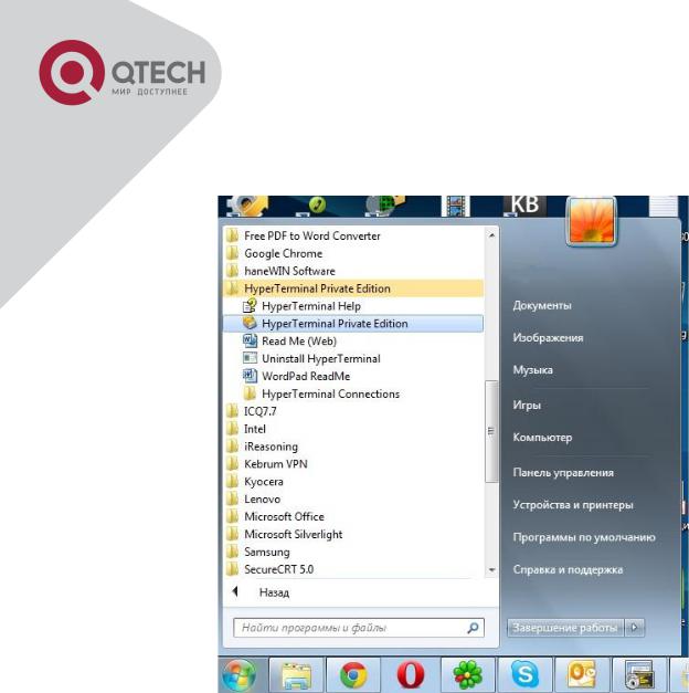
Open the HyperTerminal included in Windows after the connection established. The example below is based on the HyperTerminal included in Windows XP.
Click Start menu - All Programs -Accessories -Communication - HyperTerminal.
+7(495) 797-3311 www.qtech.ru
Москва, Новозаводская ул., 18, стр. 1
17

Opening Hyper Terminal
Type a name for opening HyperTerminal, such as “Switch”.
Opening HyperTerminal
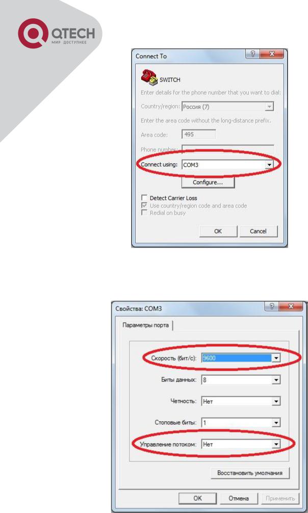
In the “Connecting using” drop-list, select the RS-232 serial port used by the PC, e.g. COM1, and click “OK”.
+7(495) 797-3311 www.qtech.ru
Москва, Новозаводская ул., 18, стр. 1
18
Opening HyperTerminal
COM1 property appears, select “9600” for “Baud rate”, “8” for “Data bits”, “none” for “Parity checksum”, “1” for stop bit and “none” for traffic control; or, you can also click “Restore default” and click “OK”.
+7(495) 797-3311 www.qtech.ru
Москва, Новозаводская ул., 18, стр. 1
19
Opening HyperTerminal
Step 3: Entering switch CLI interface
Power on the switch, the following appears in the HyperTerminal windows, that is the CLI
configuration mode for Switch.
Testing RAM...
0x077C0000 RAM OK
Loading MiniBootROM...
Attaching to file system ...
Loading nos.img ... done.
Booting......
Starting at 0x10000...
Attaching to file system ...
……
--- Performing Power-On Self Tests (POST) ---
DRAM Test.................... |
PASS! |
|
PCI |
Device 1 Test............ |
PASS! |
FLASH Test................... |
PASS! |
|
FAN |
Test..................... |
PASS! |
Done All Pass.
------------------ DONE ---------------------
Current time is SUN JAN 01 00:00:00 2006
……
Switch>
The user can now enter commands to manage the switch. For a detailed description for the commands, please refer to the following chapters.
1.1.2 In-band Management
In-band management refers to the management by login to the switch using Telnet, or using HTTP, or using SNMP management software to configure the switch. In-band management enables management of the switch for some devices attached to the switch. In the case when in-band management fails due to switch configuration changes, out-of-band management can be used for configuring and managing the switch.
+7(495) 797-3311 www.qtech.ru
Москва, Новозаводская ул., 18, стр. 1
20

1.1.2.1 Management via Telnet
To manage the switch with Telnet, the following conditions should be met: 1. Switch has an IPv4/IPv6 address configured;
The host IP address (Telnet client) and the switch’s VLAN interface IPv4/IPv6 address is in the same network segment;
If 2. is not met, Telnet client can connect to an IPv4/IPv6 address of the switch via other devices, such as a router.
The switch is a Layer 2 switch that can be configured with several IP addresses, the configuration method refers to the relative chapter. The following example assumes the shipment status of the switch where only VLAN1 exists in the system.
The following describes the steps for a Telnet client to connect to the switch’s VLAN1 interface by Telnet(IPV4 address example):
Connected with cable
Manage the switch by Telnet
Step 1: Configure the IP addresses for the switch and start the Telnet Server function on the switch.
First is the configuration of host IP address. This should be within the same network segment as the switch VLAN1 interface IP address. Suppose the switch VLAN1 interface IP address is
10.1.128.251/24. Then, a possible host IP address is 10.1.128.252/24. Run “ping 10.1.128.251” from the host and verify the result, check for reasons if ping failed.
The IP address configuration commands for VLAN1 interface are listed below. Before in-band management, the switch must be configured with an IP address by out-of-band management (i.e. Console mode), the configuration commands are as follows (All switch configuration prompts are assumed to be “Switch” hereafter if not otherwise specified):
Switch>
Switch>enable
+7(495) 797-3311 www.qtech.ru
Москва, Новозаводская ул., 18, стр. 1
21
Switch#config Switch(config)#interface vlan 1
Switch(Config-if-Vlan1)#ip address 10.1.128.251 255.255.255.0 Switch(Config-if-Vlan1)#no shutdown
To enable the Telnet Server function, users should type the CLI command telnet-server enable in the global mode as below:
Switch>enable
Switch#config
Switch(config)# telnet-server enable
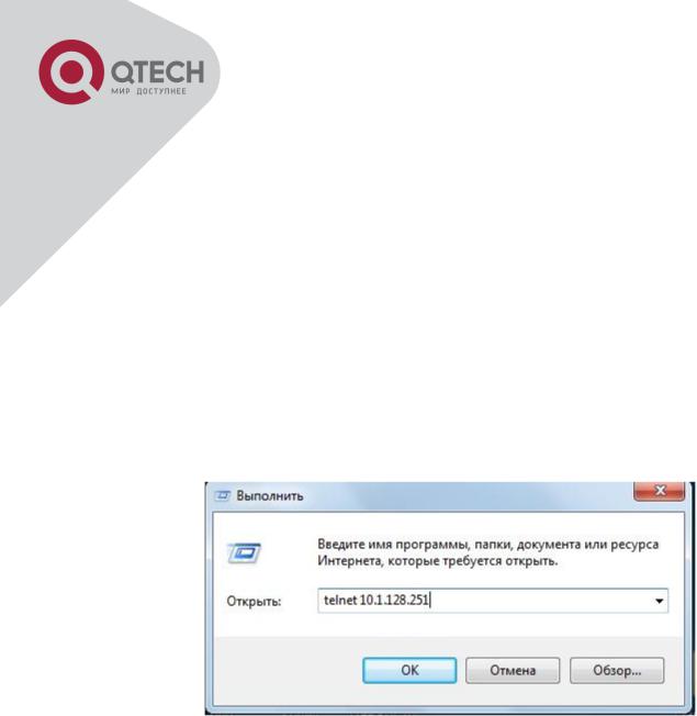
Step 2: Run Telnet Client program.
Run Telnet client program included in Windows with the specified Telnet target.
Run telnet client program included in Windows
Step 3: Login to the switch.
Login to the Telnet configuration interface. Valid login name and password are required, otherwise the switch will reject Telnet access. This is a method to protect the switch from unauthorized access. As a result, when Telnet is enabled for configuring and managing the switch, username and password for authorized Telnet users must be configured with the following command: username <username> privilege <privilege> [password (0|7) <password>]. To open the local authentication style with the following command: authentication line vty login local. Privilege option must exist and just is 15. Assume an authorized user in the switch has a username of “test”, and password of “test”, the configuration procedure should like the following:
Switch>enable
Switch#config
+7(495) 797-3311 www.qtech.ru
Москва, Новозаводская ул., 18, стр. 1
22
Switch(config)#username test privilege 15 password 0 test Switch(config)#authentication line vty login local
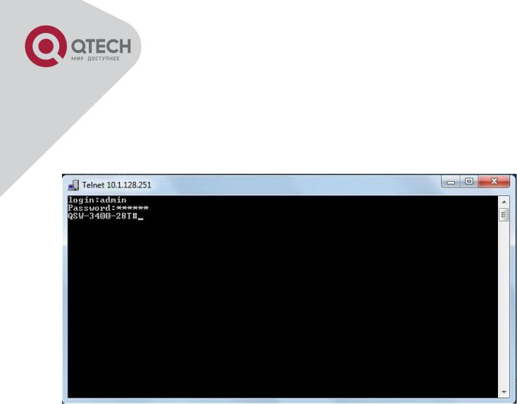
Enter valid login name and password in the Telnet configuration interface, Telnet user will be able to enter the switch’s CLI configuration interface. The commands used in the Telnet CLI interface after login is the same as that in the Console interface.
Telnet Configuration Interface
1.1.2.2 Management via HTTP
To manage the switch via HTTP, the following conditions should be met: 1. Switch has an IPv4/IPv6 address configured;
The host IPv4/IPv6 address (HTTP client) and the switch’s VLAN interface IPv4/IPv6 address are in the same network segment;
If 2. is not met, HTTP client should connect to an IPv4/IPv6 address of the switch via other devices, such as a router.
Similar to management the switch via Telnet, as soon as the host succeeds to ping/ping6 an IPv4/IPv6 address of the switch and to type the right login password, it can access the switch via HTTP. The configuration list is as below:
Step 1: Configure the IP addresses for the switch and start the HTTP server function on the switch.
For configuring the IP address on the switch through out-of-band management, see the telnet
+7(495) 797-3311 www.qtech.ru
Москва, Новозаводская ул., 18, стр. 1
23
management chapter.
To enable the WEB configuration, users should type the CLI command IP http server in the global mode as below:
Switch>enable
Switch#config Switch(config)#ip http server
Step 2: Run HTTP protocol on the host.
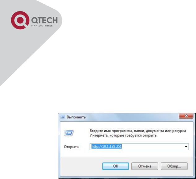
Open the Web browser on the host and type the IP address of the switch, or run directly the HTTP protocol on the Windows. For example, the IP address of the switch is “10.1.128.251”;
Run HTTP Protocol
When accessing a switch with IPv6 address, it is recommended to use the Firefox browser with 1.5 or later version. For example, if the IPv6 address of the switch is 3ffe:506:1:2::3. Input the IPv6 address of the switch is http://[3ffe:506:1:2::3] and the address should draw together with the square brackets.
Step 3: Login to the switch.
Login to the Web configuration interface. Valid login name and password are required, otherwise the switch will reject HTTP access. This is a method to protect the switch from unauthorized access. As a result, when Telnet is enabled for configuring and managing the switch, username and password for authorized Telnet users must be configured with the following command: username <username> privilege <privilege> [password (0|7) <password>]. To open the local authentication style with the following command: authentication line web login local. Privilege option must exist and just is 15. Assume an authorized user in the switch has a username of “admin”, and password of “admin”, the configuration procedure should like the following:
Switch>enable
+7(495) 797-3311 www.qtech.ru
Москва, Новозаводская ул., 18, стр. 1
24
Switch#config
Switch(config)#username admin privilege 15 password 0 admin Switch(config)#authentication line web login local
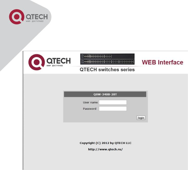
The Web login interface of QSW3400-28T-POE is as below:
Web Login Interface
Input the right username and password, and then the main Web configuration interface is shown as below.
+7(495) 797-3311 www.qtech.ru
Москва, Новозаводская ул., 18, стр. 1
25
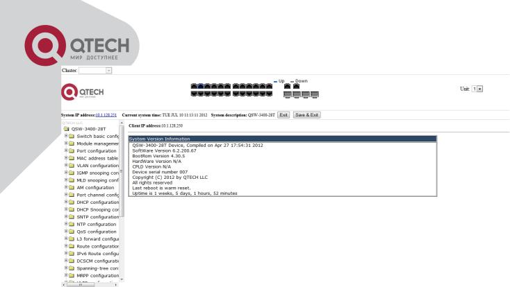
Main Web Configuration Interface
Notice: When configure the switch, the name of the switch is composed with English letters.
1.1.2.3 Manage the Switch via SNMP Network Management Software
The necessities required by SNMP network management software to manage switches: 1. IP addresses are configured on the switch;
The IP address of the client host and that of the VLAN interface on the switch it subordinates to should be in the same segment;
If 2. is not met, the client should be able to reach an IP address of the switch through devices like routers;
SNMP should be enabled.
The host with SNMP network management software should be able to ping the IP address of the switch, so that, when running, SNMP network management software will be able to find it and implement read/write operation on it. Details about how to manage switches via SNMP network management software will not be covered in this manual, please refer to “Snmp network management software user manual”.
1.2 CLI Interface
The switch provides thress management interface for users: CLI (Command Line Interface) interface, Web interface, Snmp netword management software. We will introduce the CLI interface and Web configuration interface in details, Web interface is familiar with CLI interface function and will not be covered, please refer to “Snmp network management software user manual”.
+7(495) 797-3311 www.qtech.ru
Москва, Новозаводская ул., 18, стр. 1
26

CLI interface is familiar to most users. As aforementioned, out-of-band management and Telnet login are all performed through CLI interface to manage the switch.
CLI Interface is supported by Shell program, which consists of a set of configuration commands. Those commands are categorized according to their functions in switch configuration and management. Each category represents a different configuration mode. The Shell for the switch is described below:
Configuration Modes
Configuration Syntax
Shortcut keys
Help function
Input verification
Fuzzy match support
1.2.1 Configuration Modes
Shell Configuration Modes
1.2.1.1 User Mode
On entering the CLI interface, entering user entry system first. If as common user, it is defaulted to User Mode. The prompt shown is “Switch>“, the symbol “>“ is the prompt for User
Mode. When exit command is run under Admin Mode, it will also return to the User Mode. Under User Mode, no configuration to the switch is allowed, only clock time and version
+7(495) 797-3311 www.qtech.ru
Москва, Новозаводская ул., 18, стр. 1
27

information of the switch can be queries.
1.2.1.2 Admin Mode
To Admin Mode sees the following: In user entry system, if as Admin user, it is defaulted to
Admin Mode. Admin Mode prompt “Switch#” can be entered under the User Mode by running the enable command and entering corresponding access levels admin user password, if a password has been set. Or, when exit command is run under Global Mode, it will also return to the Admin Mode. Switch also provides a shortcut key sequence "Ctrl+z”, this allows an easy way to exit to Admin Mode from any configuration mode (except User Mode).
Under Admin Mode, the user can query the switch configuration information, connection status and traffic statistics of all ports; and the user can further enter the Global Mode from Admin Mode to modify all configurations of the switch. For this reason, a password must be set for entering Admin mode to prevent unauthorized access and malicious modification to the switch.
1.2.1.3 Global Mode
Type the config command under Admin Mode will enter the Global Mode prompt
“Switch(config)#”. Use the exit command under other configuration modes such as Port Mode,
VLAN mode will return to Global Mode.
The user can perform global configuration settings under Global Mode, such as MAC Table, Port Mirroring, VLAN creation, IGMP Snooping start and STP, etc. And the user can go further to Port Mode for configuration of all the interfaces.
1.2.1.4 Interface Mode
Use the interface command under Global Mode can enter the interface mode specified. Switch provides three interface type: 1. VLAN interface; 2. Ethernet port; 3. port-channel, accordingly the three interface configuration modes.
|
Interface Type |
|
|
Entry |
|
|
Operates |
|
|
Exit |
|
|
|
|
|
|
|
|
|
||||
|
VLAN |
|
|
Type interface vlan <Vlan- |
|
|
Configure switch IPs, |
|
|
Use the exit |
|
|
Interface |
|
|
id> command under Global |
|
|
etc |
|
|
command to return to |
|
|
|
|
|
Mode. |
|
|
|
|
|
Global Mode. |
|
|
Ethernet Port |
|
|
Type interface ethernet |
|
|
Configure supported |
|
|
Use the exit |
|
|
|
|
|
<interface-list> command |
|
|
duplex mode, speed, |
|
|
command to return to |
|
|
|
|
|
under Global Mode. |
|
|
etc. of Ethernet Port. |
|
|
Global Mode. |
|
|
port-channel |
|
|
Type interface port-channel |
|
|
Configure port-channel |
|
|
Use the exit |
|
|
|
|
|
<port-channel-number> |
|
|
related settings such |
|
|
command to return to |
|
|
|
|
|
command under Global |
|
|
as duplex mode, |
|
|
Global Mode. |
|
|
|
|
|
Mode. |
|
|
speed, etc. |
|
|
|
|
+7(495) 797-3311 www.qtech.ru
Москва, Новозаводская ул., 18, стр. 1
28

1.2.1.5 VLAN Mode
Using the vlan <vlan-id> command under Global Mode can enter the corresponding VLAN Mode. Under VLAN Mode the user can configure all member ports of the corresponding VLAN. Run the exit command to exit the VLAN Mode to Global Mode.
1.2.1.6 DHCP Address Pool Mode
Type the ip dhcp pool <name> command under Global Mode will enter the DHCP Address
Pool Mode prompt “Switch(Config-<name>-dhcp)#”. DHCP address pool properties can be configured under DHCP Address Pool Mode. Run the exit command to exit the DHCP Address Pool Mode to Global Mode.
1.2.1.7 ACL Mode
|
ACL type |
|
|
Entry |
|
|
Operates |
|
|
Exit |
|
|
|
|
|
|
|
|
|
||||
|
Standard IP |
|
|
Type ip access-list |
|
|
Configure parameters for |
|
|
Use the exit |
|
|
ACL Mode |
|
|
standard command under |
|
|
Standard IP ACL Mode. |
|
|
command to return |
|
|
|
|
|
Global Mode. |
|
|
|
|
|
to Global Mode. |
|
|
Extended IP |
|
|
Type ip access-list |
|
|
Configure parameters for |
|
|
Use the exit |
|
|
ACL Mode |
|
|
extanded command under |
|
|
Extended IP ACL Mode. |
|
|
command to return |
|
|
|
|
|
Global Mode. |
|
|
|
|
|
to Global Mode. |
|
1.2.2 Configuration Syntax
Switch provides various configuration commands. Although all the commands are different, they all abide by the syntax for Switch configuration commands. The general commands format of Switch is shown below:
cmdtxt <variable> {enum1 | … | enumN } [option1 | … | optionN]
Conventions: cmdtxt in bold font indicates a command keyword; <variable> indicates a variable parameter; {enum1 | … | enumN } indicates a mandatory parameter that should be selected from the parameter set enum1~enumN; and the square bracket ([ ]) in [option1 | … | optionN] indicate an optional parameter. There may be combinations of “< >“, “{ }” and “[ ]” in the command line, such as [<variable>], {enum1 <variable>| enum2}, [option1 [option2]], etc.
Here are examples for some actual configuration commands:
show version, no parameters required. This is a command with only a keyword and no parameter, just type in the command to run.
vlan <vlan-id>, parameter values are required after the keyword.
+7(495) 797-3311 www.qtech.ru
Москва, Новозаводская ул., 18, стр. 1
29
Loading...