


 Loading...

Error! Use the Home tab to apply
1 to the text that you want to appear here. Error! Use the Home tab to apply 1 to the text that you want to appear here.
SuperDVR & H.264 Series Cards
User Manual
|
CONTENTS |
|
1.1 |
Summarization............................................................................................... |
5 |
1.2 |
System Requirements ................................................................................... |
7 |
1.2.1 QSDT4PCRC/QSDT4PCRP Card System Requirements .............................................. |
7 |
|
1.2.2 QSDT8PCRP Card System Requirements..................................................................... |
8 |
|
1.2.3 QSPD4116 Card System Requirements......................................................................... |
9 |
|
1.3 |
System Specifications.................................................................................. |
10 |
2.1 |
Video Capture Card Hardware ..................................................................... |
11 |
2.1.1 QSDT4PCRC Card Hardware....................................................................................... |
11 |
|
2.1.2 QSDT4PCRP Card Hardware...................................................................................... |
12 |
|
2.1.3 QSDT8PCRP Card Hardware...................................................................................... |
14 |
|
2.1.4 QSPD4116 Card Hardware.......................................................................................... |
15 |
|
2.1.5 Alarm Board Hardware ................................................................................................ |
17 |
|
2.1.6 Connect Audio Signal .................................................................................................. |
17 |
|
2.2 |
Install Video Capture Card Driver ................................................................ |
18 |
3.1 |
Display Control Panel.................................................................................. |
22 |
3.1.1 Display Control Panel .................................................................................................. |
22 |
|
3.1.2 Display Modes............................................................................................................. |
22 |
|
3.1.3 Flip Pages ................................................................................................................... |
22 |
|
3.1.4 Auto Dwell Display Mode ............................................................................................. |
23 |
|
3.1.5 Capture ....................................................................................................................... |
23 |
|
3.1.6 Urgent Record............................................................................................................. |
23 |
|
3.2 |
Login............................................................................................................ |
23 |
3.3 |
Record......................................................................................................... |
24 |
3.3.1 Record Modes ............................................................................................................. |
24 |
|
3.3.2 Record Setup .............................................................................................................. |
24 |
|
3.3.3 Record Status Panel.................................................................................................... |
25 |
|
3.3.4 Manual Record Mode .................................................................................................. |
26 |
|
3.3.5 Sensor Alarm Record Mode......................................................................................... |
26 |
|
3.3.6 Motion Detection Record Mode.................................................................................... |
26 |
|
3.3.7 Schedule Recording .................................................................................................... |
27 |
|
3.3.8 Recycling Recordings .................................................................................................. |
27 |
|
4.1 |
Basic Configuration ..................................................................................... |
28 |
4.2 |
Video Configuration..................................................................................... |
30 |
4.3 |
Motion Detection Configuration ................................................................... |
31 |
4.3.2 Set Motion Detection Area ........................................................................................... |
32 |
|
4.3.3 Clear Motion Detection Area ........................................................................................ |
32 |
|
4.4 |
Schedule Configuration ............................................................................... |
33 |
4.5 |
Motion Detection Alarm Configuration ......................................................... |
34 |
4.5.1 Alarm Triggering Conditions Configuration ................................................................... |
34 |
|
4.5.2 Alarm Record............................................................................................................... |
35 |
|
4.5.3 Alarm Output ............................................................................................................... |
35 |
|
4.5.4 Auto Mail Function....................................................................................................... |
36 |
|
4.6 |
E-map Configuration.................................................................................... |
38 |
4.6.1 Edit Map...................................................................................................................... |
38 |
|
4.6.2 View Map .................................................................................................................... |
39 |
|
4.7 |
P.T.Z Control Configuration.......................................................................... |
41 |
4.7.1 Protocol Setup............................................................................................................. |
41 |
|
4.7.2 Serial Ports Setup........................................................................................................ |
42 |
|
4.8 |
Users Configuration..................................................................................... |
43 |
4.8.1 Change User rights...................................................................................................... |
43 |
|
4.8.2 Add User ..................................................................................................................... |
44 |
|
2

|
|
Error! Use the Home tab to apply |
||
|
|
1 to the text that you want to |
||
|
|
appear here. Error! Use the Home |
||
SuperDVR & H.264 Series Cards |
|
|
|
|
|
|
tab to apply 1 to the text that |
||
User Manual |
|
|
you want to appear here. |
|
4.8.3 Delete User ................................................................................................................. |
|
|
44 |
|
5.1 P.T.Z |
Control …………………………………………………………………… |
|||
Error! Bookmark not defined. |
|
|
|
|
6.1 Record Search............................................................................................. |
|
|
50 |
|
6.2 Playing Back and Control ............................................................................ |
|
|
50 |
|
6.3 Other Functions........................................................................................... |
|
|
53 |
|
6.3.1 Recorded File Backup ................................................................................................. |
|
|
53 |
|
6.3.2 Delete Recorded Files ................................................................................................. |
|
|
54 |
|
6.3.3 Capture Pictures.......................................................................................................... |
|
|
55 |
|
6.3.4 Image Zoom in/out....................................................................................................... |
|
|
57 |
|
Remote Live Surveillance.................................................................................. |
|
|
59 |
|
7.1 Remote Surveillance Server Configuration.................................................. |
|
|
59 |
|
7.2 Setting up Router for Internet Access.......................................................... |
|
|
60 |
|
7.2.1 Port Forwarding........................................................................................................... |
|
|
61 |
|
7.2.2 Finding Router’s Public IP address .............................................................................. |
|
|
62 |
|
7.2.3 Dynamic Domain Name Services................................................................................. |
|
|
63 |
|
7.2.4 To Access through Internet Explorer............................................................................. |
|
|
63 |
|
7.2.5 Unknown Publisher or Unsigned Program Error ........................................................... |
|
|
65 |
|
7.3 Accessing IE client....................................................................................... |
|
|
65 |
|
7.4 Remote playback......................................................................................... |
|
|
69 |
|
7.4.1 Record playback and control........................................................................................ |
|
|
69 |
|
7.5 System setup............................................................................................... |
|
|
72 |
|
7.5.1 Basic Configuration...................................................................................................... |
|
|
73 |
|
7.5.2 Camera setup.............................................................................................................. |
|
|
74 |
|
7.5.3 Schedule configuration ................................................................................................ |
|
|
75 |
|
7.5.4 Alarm configuration...................................................................................................... |
|
|
76 |
|
7.5.5 Record configuration.................................................................................................... |
|
|
77 |
|
7.5.6 Motion configuration .................................................................................................... |
|
|
78 |
|
7.5.7 EMAIL Configuration.................................................................................................... |
|
|
79 |
|
7.5.8 P.T.Z Configuration ...................................................................................................... |
|
|
81 |
|
7.6 Mobile Surveillance ..................................................................................... |
|
|
83 |
|
7.6.1 Introduction to Mobile Surveillance............................................................................... |
|
|
83 |
|
7.7 By Smart Phone with Win Mobile Pro or Classic Operating System............ |
83 |
|||
7.8 By Smart Phone with Symbian Operating System....................................... |
|
86 |
||
Appendix1 |
Frequently Asked Questions ....................................................... |
|
|
90 |
Appendix 2.1 Installation ................................................................................... |
|
|
90 |
|
Appendix 2.1.1 Cannot Install the SuperDVR Driver ............................................................. |
|
|
90 |
|
Appendix 2.1.2 Can’t find H.264 series Devices in Device Manager...................................... |
|
90 |
||
Appendix 2.2 How to Use SuperDVR................................................................ |
|
|
90 |
|
Appendix 2.2.1 Meanings of the indicator lights .................................................................... |
|
|
90 |
|
Appendix 2.2.2 How do the different record modes work?..................................................... |
|
|
90 |
|
Appendix 2.2.3 How to set recycling record mode on the system .......................................... |
|
91 |
||
Appendix 2.2.4 How to set auto reboot function .................................................................... |
|
|
91 |
|
Appendix 2.2.5 How to quickly setup the schedule record function........................................ |
|
91 |
||
Appendix 2.2.6 What are the byte rates for different image qualities from highest to normal? 91 |
||||
Appendix 2.2.7 The frame rate seems to be lower than what I set......................................... |
|
91 |
||
Appendix 2.2.8 Why can’t I select more channels to backup? ............................................... |
|
91 |
||
Appendix 2.3 How to Use Network Function ..................................................... |
|
|
92 |
|
Appendix 2.3.1 How to monitor on the client-side.................................................................. |
|
|
92 |
|
Appendix 2.3.2 Why can’t I download the client-side software?............................................. |
|
92 |
||
Appendix 2.3.3 Why can’t the server be configured at the client-side? .................................. |
|
92 |
||
3

Error! Use the Home tab to apply
1 to the text that you want to appear here. Error! Use the Home tab to apply 1 to the text that you want to appear here.
SuperDVR & H.264 Series Cards
User Manual
Appendix 2.3.4 Why can’t I see the images?......................................................................... |
92 |
|
Appendix 2.3.5 What should I do if the Internet speed is quite slow?..................................... |
93 |
|
Appendix 2.3.6 Why can’t I start Webcam server or RPB server? ......................................... |
93 |
|
Appendix 2.3.7 How much hard drive space do the recorded files take up?........................... |
93 |
|
Appendix 2.4 Other Questions .......................................................................... |
94 |
|
Appendix 2.4.1 Why doesn’t the computer display work, or why can’t I access Window system? |
||
............................................................................................................................................ |
|
94 |
Appendix 2.4.2 Why I can’t find the recorded files?............................................................... |
94 |
|
Appendix 2.4.3 Why is the screen’s display unstable with dithering and water-wave images? 94 |
||
Appendix 2.4.4 Why does it delay playing back, and why is it slow to close and open the driver? |
||
............................................................................................................................................ |
|
94 |
Appendix 2.4.5 Why can’t I play back? ................................................................................. |
95 |
|
Appendix 2.4.6 Why do I see some gray blocks on time progress bar area when playing back? |
||
............................................................................................................................................ |
|
95 |
Appendix 2.4.7 Why could I see some old recording sections that weren’t available for play |
||
back? ................................................................................................................................... |
|
95 |
Appendix 2.4.8 Precautions on changing system time .......................................................... |
95 |
|
Appendix 2.4.9 If system time must be changed, please do following preparations first......... |
96 |
|
Appendix 2.4.10 How to use REPAIRDB to repair SuperDVR database................................ |
96 |
|
Appendix 2.4.11 How to set power options of Microsoft VISTA system .................................. |
96 |
|
Appendix2 |
Quick Start for Using................................................................. |
96 |
Appendix 3.1 Installation Instructions ................................................................ |
96 |
|
Appendix 3.2 Troubleshooting ........................................................................... |
97 |
|
Appendix3.2.1 When opening the SuperDVR program, it says ‘ Can’t find card ’. ............... |
97 |
|
Appendix 3.2.2 How to setup the web client to monitor from Internet..................................... |
97 |
|
Appendix3 |
Function Tree............................................................................. |
99 |
Appendix 4.1 SuperDVR Function Tree............................................................. |
99 |
|
Appendix 4.2 System Configuration Tree ........................................................ |
100 |
|
Appendix 4.3 IE Client FunctionTree ............................................................... |
101 |
|
Appendix 4.4 Remote Playback Function Tree................................................ |
102 |
|
4

|
|
Error! Use the Home tab to apply |
|
|
|
1 to the text that you want to |
|
SuperDVR & H.264 Series Cards |
|
appear here. Error! Use the Home |
|
|
tab to apply 1 to the text that |
|
|
User Manual |
|
|
|
|
you want to appear here. |
|
1 Introduction
1.1 Summarization
Thank you for choosing our digital video capture cards.
4 Channel, 8 Channel and 16 Channel cards adopt H.264 compression format, and enable a maximum of 16 channels real-time surveillance in CIF resolution. Our cards are mature and cost-effective products that should be your ideal choices. They enable synchronous audio and video compression and transmission along with their powerful compression rate and network transmission function. They are widely used in banks, intelligent communities, traffic management units, medical systems, educational systems, armed forces and so on.
This manual is suitable for SuperDVR 6.2, which supports QSDT4PCRC, QSDT4PCRP, QSDT8PCRP, and QSPD4116 cards.
In this manual, you will learn how to install the hardware and driver (software), and how to setup the systems on this range of products. Please make sure your operations with the products are strictly in accordance with the manual, to maintain the stability of the digital surveillance systems.
The following are standard functions of these products:
•Schedule record mode
Users can choose any period in a day to record and set up record modes, i.e. sensor alarm record, motion detection record, manual record, Schedule Record.
•Motion detection mode
Motion detection areas are adjustable with a maximum 16 areas for each channel. Users can also set motion detection sensitivity for each channel. The system begins to record only when motion is detected is detected on the channel and after motion stops it will stop recording after a certain time period, which is adjustable by users.
•Sensor alarm record mode
The system has an external alarm which enables the system to support alarm input and output.
•Recycling record mode
Users can set recording storage sequence for HDD partitions. The recording storage will automatically switch to the next partition when the current one is full. If all the partitions are full and recycling record mode is enabled, the oldest recorded data will be covered by new data. Users can also set HDD minimum storage alarm. Then once the present storage
5

Error! Use the Home tab to apply
1 to the text that you want to appear here. Error! Use the Home tab to apply 1 to the text that you want to appear here.
SuperDVR & H.264 Series Cards
User Manual
space is less then the minimum storage and recycling record mode is not enabled, recording will automatically stop.
•P.T.Z control function
Supports a number of protocols. Users can control multiple speed domes and integrative cameras, including pan, tilt, zoom, focus and iris adjustment for P.T.Z devices. Supports preset points and auto scout.
•User management
Different users have different rights, user names and passwords, to ensure system security.
•Multi-channel display
Supports different multi-channel display modes, full screen display and auto dwell display.
•Watch dog function
The 16 Channel card has watchdog function. In case SuperDVR driver or Windows system is frozen, the watchdog will restart the computer and login to SuperDVR system again automatically.
•One PC can contain 1 to 4 cards of the same model, up to a total of 32 channels
•Supports 320x240 (NTSC), 352x288 (PAL) standard resolutions.
•Image color is adjustable for each channel, including contrast, brightness, hue and saturation.
•H.264 compression format greatly reduces HDD usage.
•Powerful video playback functions, including playing back, pause, stop, fast-forward, single-frame play and image capture.
•Supports advanced search mode. Users can search by date/time, camera, record mode, and random combination of the three methods.
•Supports recorded file backup, delete by date/time, camera.
•Conveniently extend system functions through software upgrades.
•Supports multiple languages, including Chinese (Traditional), English, German, Spanish, Portuguese and other customized languages.
•CPU and storage resource saving by advanced technology
•Remote Surveillance and P.T.Z control through LAN, Intranet, and Internet.
•Supports alarm pre-record.
•Supports buzzer, email alarm out.
•Can greatly decrease fragmented files while using NTFS partition.
•User-friendly graphical user interface.
6

|
|
Error! Use the Home tab to apply |
|
|
|
1 to the text that you want to |
|
SuperDVR & H.264 Series Cards |
|
appear here. Error! Use the Home |
|
|
tab to apply 1 to the text that |
|
|
User Manual |
|
|
|
|
you want to appear here. |
|
1.2 System Requirements
Our H.264 series cards support video cards on Windows VISTA as long as the computer that the card is installed in supports Vista, and Vista supports the video card being used.
1.2.1 QSDT4PCRC/QSDT4PCRP Card System Requirements
Card |
QSDT4PCRC/QSDT4PCRP |
|
PC Module |
||
|
||
CPU |
Intel P4 processor 2.0G minimum |
|
HDD |
100Gb minimum free space |
|
RAM |
512MB minimum |
|
|
Supports MOST* AGP and PCI-E Video Cards |
|
VIDEO CARDS |
with 64MB of RAM or more with full Direct Draw support. |
|
*Some newer PCI-E cards are not yet supported |
||
|
|
|
OS (32 bit) |
Win2000 /WinXP /VISTA |
DirectX 9.0
Table1-1 QSDT4PCRC/QSDT4PCRP System Requirements
NOTICE
1. Motherboards listed below which have passed our testing and work well with QSDT4PCRC/QSDT4PCRP:
•Intel 865G
•GA-945PL-S3E
•GA965P-S3
•GA-K8V7890-9
•GA-8IE2004P
•ASUS P5PL2
•ASUS P5B-E
2. VGA cards listed below which have passed our testing and work well with QSDT4PCRP:
•ATI X1600
•ATI X300
•NVIDIA GeForce 7300LE
•NVIDIA GeForce 7600GS
•NVIDIA GeForce 8500GT
NOTE: If recorded disk partition’s format is FAT32 and the system has run for a long time, the system will create a lot of data fragments that may result in system running slowly. It’s recommended to run a disk defragmenter every 10 to 30 days. We strongly suggest that you use NTFS format for recording disk partition.
7

Error! Use the Home tab to apply
1 to the text that you want to appear here. Error! Use the Home tab to apply 1 to the text that you want to appear here.
SuperDVR & H.264 Series Cards
User Manual
1.2.2 QSDT8PCRP Card System Requirements
|
Card |
|
QSDT8PCRP |
|
PC Module |
|
|
|
|
|
|
|
CPU |
Intel P4 processor 2.0G minimum |
|
|
HDD |
200GB minimum free space |
|
|
RAM |
512M minimum |
|
|
|
|
Supports MOST* AGP and PCI-E Video Cards |
|
VIDEO CARDS |
with 64MB of RAM or more with full Direct Draw support. |
|
|
*Some newer PCI-E cards are not yet supported |
||
|
|
|
|
|
OS (32 bit) |
Win2000/WinXP/VISTA |
|
DirectX 9.0
Table1-2 QSDT8PCRP System Requirements
Motherboards and Video cards listed below have passed our testing and work well with QSDT8PCRP in Windows XP systems:
Motherboard |
Video card |
|
COLORFUL C975X-MVP |
ATI HD2400 |
|
NVIDIA GeForce 7600 |
||
|
NVIDIA GeForce 7300 |
|
ASUS P5LD2-X |
ATI HD2400 |
|
ATI X300 |
||
|
||
|
ATI HD2400 |
|
ASUS P5B |
NVIDIA GeForce 7600 |
|
NVIDIA GeForce 7300 |
||
|
||
|
ATI X300 |
|
GA-965P-S3 |
ATI HD2400 |
|
NVIDIA GeForce 7300 |
||
|
ATI X300 |
|
GA-945PL-S3E |
ATI HD2400 |
|
NVIDIA GeForce 7600 |
||
|
ATI X300 |
|
ASUS P5L-1394 |
ATI HD2400 |
|
NVIDIA GeForce 7600 |
||
|
ATI X300 |
|
|
ATI HD2400 |
|
ASUS P5GD1-VM |
NVIDIA GeForce 7600 |
|
ATI X300 |
||
|
||
|
ATI X700 |
|
Table1-3 Motherboards and Video Cards Supporting XP |
||
Motherboards and Video cards listed below which have passed our testing and work well with QSPD4116 in Windows VISTA systems:
Motherboard |
Video card |
COLORFUL C975X-MVP |
ATI HD2400 |
8

|
|
|
|
Error! Use the Home tab to apply |
|
|
|
|
|
|
1 to the text that you want to |
|
|
SuperDVR & H.264 Series Cards |
|
|
appear here. Error! Use the Home |
|
||
|
|
tab to apply 1 to the text that |
|
|||
User Manual |
|
|
|
|||
|
|
you want to appear here. |
|
|||
|
|
|
|
|||
|
Motherboard |
Video card |
|
|||
|
ASUS P5LD2-X |
ATI HD2400 |
|
|
||
|
ATI X300 |
|
|
|||
|
|
|
||||
|
GA-965P-S3 |
ATI HD2400 |
|
|||
|
ATI X300 |
|
|
|||
|
|
|
||||
|
ASUS P5L-1394 |
ATI HD2400 |
|
|||
|
ATI X300 |
|
|
|||
|
|
|
||||
|
ASUS P5GD1-VM |
ATI HD2400 |
|
|||
|
ATI X300 |
|
||||
|
|
ATI X700 |
|
|||
|
Table1-4 Motherboards and Video Cards Support VISTA |
|||||
|
1.2.3 QSPD4116 Card System Requirements |
||
|
Card |
|
QSPD4116 |
|
PC Module |
|
|
|
|
|
|
|
CPU |
Intel P4 processor 2.0G minimum |
|
|
HDD |
200GB minimum free space |
|
|
RAM |
512MB minimum |
|
|
|
|
Supports MOST* AGP and PCI-E Video Cards |
|
VIDEO CARDS |
with 128MB of RAM or more with full Direct Draw support. |
|
|
*Some newer PCI-E cards are not yet supported |
||
|
|
|
|
|
OS (32 bit) |
Windows 2000/WinXP/VISTA |
|
|
DirectX |
9.0 |
|
|
|
|
Table1-5 QSPD4116 System Requirements |
Motherboards and Video cards listed below which have passed our testing and work well with QSPD4116 in Windows XP system:
Motherboard |
Video card |
|
COLORFUL C975X-MVP |
ATI HD2400 |
|
NVIDIA GeForce 7600 |
||
|
NVIDIA GeForce 7300 |
|
ASUS P5LD2-X |
ATI HD2400 |
|
ATI X300 |
||
|
||
|
ATI HD2400 |
|
ASUS P5B |
NVIDIA GeForce 7600 |
|
NVIDIA GeForce 7300 |
||
|
||
|
ATI X300 |
|
GA-965P-S3 |
ATI HD2400 |
|
NVIDIA GeForce 7300 |
||
|
ATI X300 |
|
GA-945PL-S3E |
ATI HD2400 |
|
NVIDIA GeForce 7600 |
||
|
ATI X300 |
|
ASUS P5L-1394 |
ATI HD2400 |
|
NVIDIA GeForce 7600 |
||
|
ATI X300 |
|
ASUS P5GD1-VM |
ATI HD2400 |
|
NVIDIA GeForce 7600 |
||
|
9

Error! Use the Home tab to apply
1 to the text that you want to appear here. Error! Use the Home tab to apply 1 to the text that you want to appear here.
SuperDVR & H.264 Series Cards
User Manual
Motherboard |
Video card |
ATI X300
ATI X700
Table1-6 Motherboards and Video Cards Supporting XP
Motherboards and Video cards listed below which have passed our testing and work well with QSPD4116 in Windows VISTA system:
Motherboard |
Video card |
|
COLORFUL C975X-MVP |
ATI HD2400 |
|
ASUS P5LD2-X |
ATI HD2400 |
|
ATI X300 |
||
|
||
GA-965P-S3 |
ATI HD2400 |
|
ATI X300 |
||
|
||
ASUS P5L-1394 |
ATI HD2400 |
|
ATI X300 |
||
|
||
ASUS P5GD1-VM |
ATI HD2400 |
|
ATI X300 |
||
|
ATI X700 |
Table1-7 Motherboards and Video Cards Supporting VISTA
1.3 System Specifications
•Format: PAL/NTSC.
•Resolution: 320x240 (NTSC), 352x288 (PAL).
•Maximum Frame rate per channel: 25 fps (PAL), 30 ftp (NTSC). Screen
set: resolution 1024×768, color quality 16 bits or 32 bits.
•Compression code rate: 50kbps – 1.2Mbps.
•Data format: H.264.
10
|
|
|
|
Error! Use the Home tab to apply |
|
|
|
|
|
|
1 to the text that you want to |
|
|
SuperDVR & H.264 Series Cards |
|
|
appear here. Error! Use the Home |
|
|
|
|
|
tab to apply 1 to the text that |
|
|
||
User Manual |
|
|
|
|
||
|
|
you want to appear here. |
|
|
||
|
|
|
|
|||
|
|
2 Hardware Installation |
||||
2.1Video Capture Card Hardware
2.1.1QSDT4PCRC Card Hardware
Figure2-1 QSDT4PCRC Video Capture Card
Pin Port |
Definition |
Interpret |
1PIN |
5V |
Power Source (5V) |
2PIN |
ALARM_COM |
Alarm COM |
3PIN |
ALARM_NC |
Alarm Normal Close |
4PIN |
ALARM_IN1 |
Alarm Input 1 |
5PIN |
ALARM_NO |
Alarm Normal Open |
6PIN |
ALARM_IN2 |
Alarm Input 2 |
7PIN |
GND |
Ground |
8PIN |
ALARM_IN3 |
Alarm Input 3 |
9PIN |
GND |
Ground |
10PIN |
ALARM_IN4 |
Alarm Input 4 |
|
Table2-1 QSDT4PCRC |
Card Pins |
11
Error! Use the Home tab to apply
1 to the text that you want to appear here. Error! Use the Home tab to apply 1 to the text that you want to appear here.
SuperDVR & H.264 Series Cards
User Manual
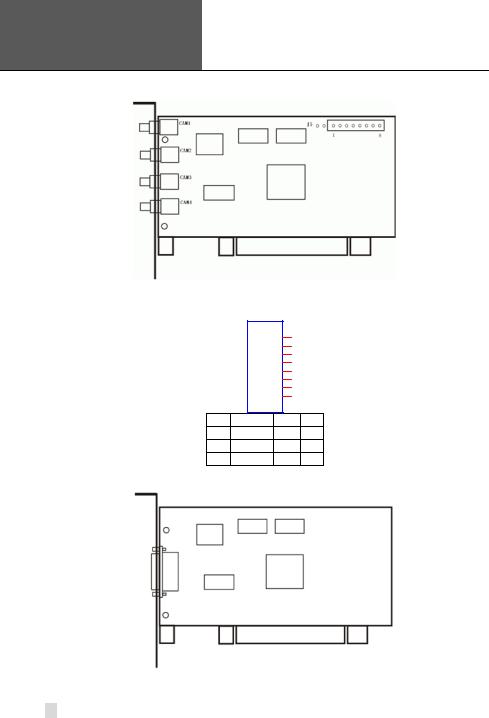
2.1.2 QSDT4PCRP Card Hardware
Figure2-2 QSDT4PCRP Video Capture Card
J5
GiL-G-8P-S3T2-E
1
2
3
4
5
6
7
8
PIN1 AUDIO-1 PIN2GND
PIN3 AUDIO-2 PIN4GND
PIN5 AUDIO-3 PIN6GND
PIN7 AUDIO-4 PIN8GND
Figure2-3 Definition of Audio Connector’s Pins
Figure2-4 QSDT4PCRP Video Capture Card
12
|
|
Error! Use the Home tab to apply |
|
|
|
1 to the text that you want to |
|
SuperDVR & H.264 Series Cards |
|
appear here. Error! Use the Home |
|
|
tab to apply 1 to the text that |
|
|
User Manual |
|
|
|
|
you want to appear here. |
|
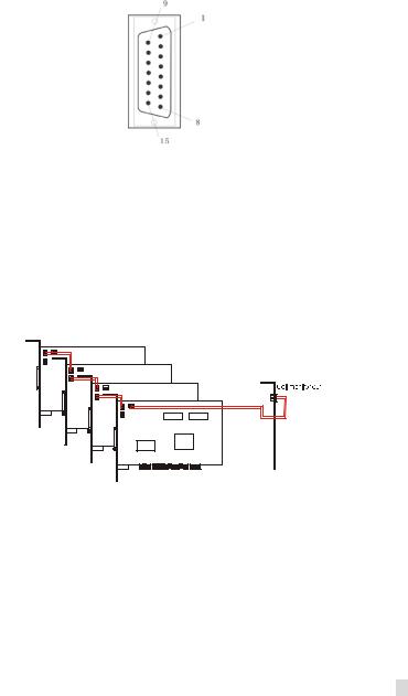
|
PIN1 |
VIDEO- |
1PIN9 |
GND |
|
|
PIN2 |
GND |
PIN10 |
AUDIO-1 |
|
|
PIN3 |
VIDEO- |
2PIN11 |
AUDIO-2 |
|
|
PIN4 |
GND |
PIN12 |
AUDIO-3 |
|
|
PIN5 |
VIDEO- |
3PIN13 |
AUDIO-4 |
|
|
PIN6 |
GND |
PIN14 |
NULL |
|
|
PIN7 |
VIDEO- |
4PIN15 |
GND |
|
|
PIN8 |
GND |
|
|
Connector’s Pins |
Figure2-5 Definition of Audio and Video |
|||||
When there are multiple QSDT4PCRP cards connected together, please connect the lines as in the following figure:
Figure2-6 |
Multi-Card Connection |
13
Error! Use the Home tab to apply
1 to the text that you want to appear here. Error! Use the Home tab to apply 1 to the text that you want to appear here.
SuperDVR & H.264 Series Cards
User Manual
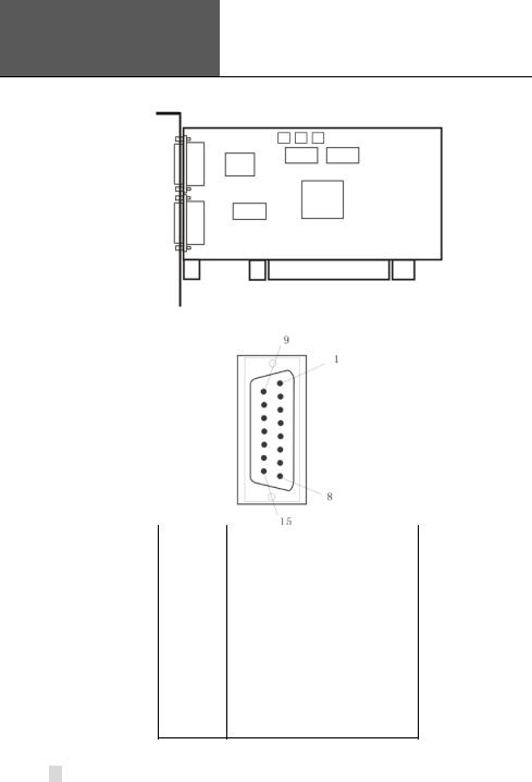
2.1.3 QSDT8PCRP Card Hardware
Figure2-7 QSDT8PCRP Video Capture Card
PIN1 |
VIDEO-1 |
PIN9 |
GND |
|
|
|
|
PIN2 |
GND |
PIN10 |
AUDIO-1 |
|
|
|
|
PIN3 |
VIDEO-2 |
PIN11 |
AUDIO-2 |
|
|
|
|
PIN4 |
GND |
PIN12 |
AUDIO-3 |
|
|
|
|
PIN5 |
VIDEO-3 |
PIN13 |
AUDIO-4 |
|
|
|
|
PIN6 |
GND |
PIN14 |
NULL |
|
|
|
|
PIN7 |
VIDEO-4 |
PIN15 |
GND |
|
|
|
|
PIN8 |
|
GND |
|
Figure2-8 Definition of Audio and Video Connector’s Pins
14
|
|
Error! Use the Home tab to apply |
|
|
|
1 to the text that you want to |
|
SuperDVR & H.264 Series Cards |
|
appear here. Error! Use the Home |
|
|
tab to apply 1 to the text that |
|
|
User Manual |
|
|
|
|
you want to appear here. |
|
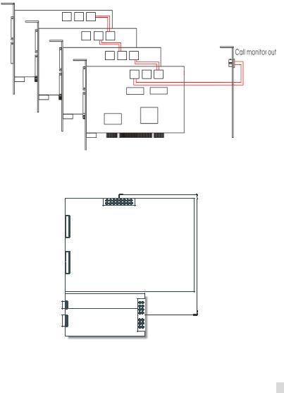
When there are multiple QSDT8PCRP cards connected together, please connect the line as in the following figure:
Figure2-9 Multi-Card Connection
2.1.4 QSPD4116 Card Hardware
Data Line
Video Line 1-8
Video Line 9-16
Motherboard
Call Monitor
Data Line 
Audio Line 1-16
Accessorial board
Figure2-10QSPD4116 Video Capture Card
The Call Monitor interface is used to connect the spot monitor.
15

Error! Use the Home tab to apply
1 to the text that you want to appear here. Error! Use the Home tab to apply 1 to the text that you want to appear here.
SuperDVR & H.264 Series Cards
User Manual
|
|
|
|
|
|
P2 |
|
|
|
|
|
|
|
|
|
|
|
|
|
|
|
|
|
|
|
|
|
|
|
|
|
|
|||
|
|
|
|
DFD202-F-26-R-T |
|
|
|
|
|
|
|||||||||||||||||||||||||
|
|
|
|
|
1 |
|
|
|
|
|
|
|
|
|
|
10 |
|
|
|
|
|
|
|||||||||||||
|
|
|
|
|
|
|
|
|
|
|
|
|
|
|
|
|
|
|
|
|
|||||||||||||||
|
|
|
|
|
|
|
|
|
|
|
|
|
|
|
|
19 |
|
|
|
|
|
|
|||||||||||||
|
|
|
|
|
2 |
|
|
|
|
|
|
|
|
|
|
|
11 |
|
|
|
|
|
|
||||||||||||
|
|
|
|
|
|
|
|
|
|
|
|
|
|
|
|
20 |
|
|
|
|
|
|
|||||||||||||
|
|
|
|
|
3 |
|
|
|
|
|
|
|
|
|
|
|
12 |
|
|
|
|
|
|
||||||||||||
|
|
|
|
|
|
|
|
|
|
|
|
|
|
|
|
21 |
|
|
|
|
|
|
|||||||||||||
|
|
|
|
|
4 |
|
|
|
|
|
|
|
|
|
|
|
13 |
|
|
|
|
|
|
||||||||||||
|
|
|
|
|
|
|
|
|
|
|
|
|
|
|
|
22 |
|
|
|
|
|
|
|||||||||||||
|
|
|
|
|
5 |
|
|
|
|
|
|
|
|
|
|
|
14 |
|
|
|
|
|
|
||||||||||||
|
|
|
|
|
|
|
|
|
|
|
|
|
|
|
|
23 |
|
|
|
|
|
|
|||||||||||||
|
|
|
|
|
6 |
|
|
|
|
|
|
|
|
|
|
|
15 |
|
|
|
|
|
|
||||||||||||
|
|
|
|
|
|
|
|
|
|
|
|
|
|
|
|
24 |
|
|
|
|
|
|
|||||||||||||
|
|
|
|
|
7 |
|
|
|
|
|
|
|
|
|
|
|
16 |
|
|
|
|
|
|
||||||||||||
|
|
|
|
|
|
|
|
|
|
|
|
|
|
|
|
25 |
|
|
|
|
|
|
|||||||||||||
|
|
|
|
|
8 |
|
|
|
|
|
|
|
|
|
|
|
17 |
|
|
|
|
|
|
||||||||||||
|
|
|
|
|
|
|
|
|
|
|
|
|
|
|
|
26 |
|
|
|
|
|
|
|||||||||||||
|
|
|
|
|
9 |
|
|
|
|
|
|
|
|
|
|
|
18 |
|
|
|
|
|
|
||||||||||||
|
|
|
|
|
|
|
|
|
|
|
|
|
|
|
|
|
|
|
|
|
|
|
|
|
|
|
|
|
|
|
|
|
|
|
|
|
|
|
|
|
|
|
|
|
|
|
|
|
|
|
|
|
|
|
|
|
|
|
|
|
|
|
|
|
|
|
|
|
|
|
|
|
|
|
|
|
|
|
|
|
|
|
|
|
|
|
|
|
|
|
|
|
|
|
|
|
|
|
|
|
|
|
|
|
|
|
|
|
|
|
|
|
|
|
|
|
|
27 |
|
|
|
|
|
|
|
|
|
|
|
|
|
|
|
|
|
|
|
|
|
|
|
|
|
|
|
|
|
|
|
|
|
|
|
|
|
|
|
|
|
||||||||||||||||||||
|
|
|
|
|
|
|
|
|
|
|
|
|
|
||||||||||||||||||||||
|
|
PIN1 |
AUDIO2 |
|
|
PIN11 |
AUDIO3 |
|
|
|
|||||||||||||||||||||||||
|
|
PIN2 |
AUDIO4 |
|
|
PIN12 |
AUDIO5 |
|
|
|
|||||||||||||||||||||||||
|
|
PIN3 |
AUDIO6 |
|
|
PIN13 |
AUDIO7 |
|
|
|
|||||||||||||||||||||||||
|
|
PIN4 |
AUDIO8 |
|
|
PIN14 |
AUDIO9 |
|
|
|
|||||||||||||||||||||||||
|
|
PIN5 |
AUDIO10 |
|
|
PIN15 |
AUDIO11 |
|
|
|
|||||||||||||||||||||||||
|
|
PIN6 |
AUDIO12 |
|
|
PIN16 |
AUDIO13 |
|
|
|
|||||||||||||||||||||||||
|
|
PIN7 |
AUDIO14 |
|
|
PIN17 |
|
|
|
|
|
|
|||||||||||||||||||||||
|
|
PIN8 |
AUDIO15 |
|
|
|
|
|
|
|
|
|
|
|
|
|
|
|
|
|
|
|
|
GND |
|
|
|
||||||||
|
|
PIN9 |
AUDIO16 |
|
/ |
|
|
|
|
|
|
|
|
|
|
|
|
|
|
|
|
|
|
|
|
|
|
|
|
||||||
|
|
PIN10 |
AUDIO1 |
|
|
PIN26 |
|
|
|
|
|
|
|||||||||||||||||||||||
Figure2-11Audio Connector and Pins Definition |
|||||||||||||||||||||||||||||||||||
|
J1 |
|
|
|
|
|
|
|
|
|
|
|
|
|
|
|
|
|
|
|
|
|
|
|
|
|
|
|
|
J2 |
|||||
GiL-G-8P-S3T2-E |
|
|
|
|
|
|
|
|
|
|
|
|
|
|
|
|
|
|
|
|
|
|
|
|
|
|
|
GiL-G-8P-S3T2-E |
|||||||
|
|
|
|
|
|
|
|
|
|
|
|
|
|
|
|
|
|
|
|
|
|
|
|
|
|
|
|
|
|
|
|
|
|||
|
1 |
|
|
|
|
|
|
|
|
|
|
|
|
|
|
|
|
|
|
|
|
|
|
|
|
|
|
|
|
1 |
|
|
|||
|
|
|
|
|
|
|
|
|
|
|
|
|
|
|
|
|
|
|
|
|
|
|
|
|
|
|
|
|
|
|
|||||
|
2 |
|
|
|
|
|
|
|
|
|
|
|
|
|
|
|
|
|
|
|
|
|
|
|
|
|
|
|
|
2 |
|
|
|||
|
3 |
|
|
|
|
|
|
|
|
|
|
|
|
|
|
|
|
|
|
|
|
|
|
|
|
|
|
|
|
3 |
|
|
|||
|
4 |
|
|
|
|
|
|
|
|
|
|
|
|
|
|
|
|
|
|
|
|
|
|
|
|
|
|
|
|
4 |
|
|
|||
|
5 |
|
|
|
|
|
|
|
|
|
|
|
|
|
|
|
|
|
|
|
|
|
|
|
|
|
|
|
|
5 |
|
|
|||
|
6 |
|
|
|
|
|
|
|
|
|
|
|
|
|
|
|
|
|
|
|
|
|
|
|
|
|
|
|
|
6 |
|
|
|||
|
7 |
|
|
|
|
|
|
|
|
|
|
|
|
|
|
|
|
|
|
|
|
|
|
|
|
|
|
|
|
7 |
|
|
|||
|
8 |
|
|
|
|
|
|
|
|
|
|
|
|
|
|
|
|
|
|
|
|
|
|
|
|
|
|
|
|
8 |
|
|
|||
|
|
|
|
|
|
|
|
|
|
|
|
|
|
|
|
|
|
|
|
|
|
|
|
|
|
|
|
||||||||
|
|
|
|
|
|
|
|
|
|
|
|
|
|
|
|
|
|
|
|
|
|
||||||||||||||
PIN1 VIN-1 PIN2 GND |
|
|
|
|
|
|
|
|
|
|
|
|
|
|
|
|
|
|
|
PIN1 VIN-5PIN2 GND |
|||||||||||||||
PIN3 VIN-2 PIN4 GND |
|
|
|
|
|
|
|
|
|
|
|
|
|
|
|
|
|
|
|
|
PIN3 VIN-6PIN4 GND |
||||||||||||||
PIN5 VIN-3 PIN6 GND |
|
|
|
|
|
|
|
|
|
|
|
|
|
|
|
|
|
|
|
|
PIN5 VIN-7PIN6 GND |
||||||||||||||
PIN7 VIN-4 PIN8 GND |
|
|
|
|
|
|
|
|
|
|
|
|
|
|
|
|
|
|
|
PIN7 VIN-8PIN8 GND |
|||||||||||||||
Figure2-12Video Pins Definition
16
|
|
Error! Use the Home tab to apply |
|
|
|
1 to the text that you want to |
|
SuperDVR & H.264 Series Cards |
|
appear here. Error! Use the Home |
|
|
tab to apply 1 to the text that |
|
|
User Manual |
|
|
|
|
you want to appear here. |
|
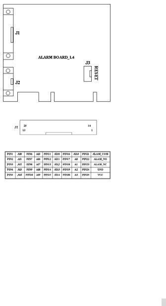
2.1.5 Alarm Board Hardware
Figure2-13Alarm Board
Figure2-14Pins Definition of Alarm Board
Connect J2 to PC serial port and you can use alarm board on SuperDVR system.
2.1.6 Connect Audio Signal
For QSDT4PCRP, connect the audio input device to the microphone connector on the motherboard.
Before installing the Video Capture Card hardware in PCI port of the motherboard, make sure you’ve installed Microsoft DirectX 9.0 or later. Then turn on the computer, the system will display ‘Found new hardware’.
NOTICE: Just click ‘Cancel’ and ignore the pop-up message.
Insert the CD that contains H.264 series capture card driver into the CD tray, and run Setup.exe program to install the driver. The default installation path is ‘C:\Program Files\SuperDVR’.
17
Error! Use the Home tab to apply
1 to the text that you want to appear here. Error! Use the Home tab to apply 1 to the text that you want to appear here.
SuperDVR & H.264 Series Cards
User Manual
NOTICE: If you get the error message “Can’t find card” when running the SuperDVR software, try restarting the computer.
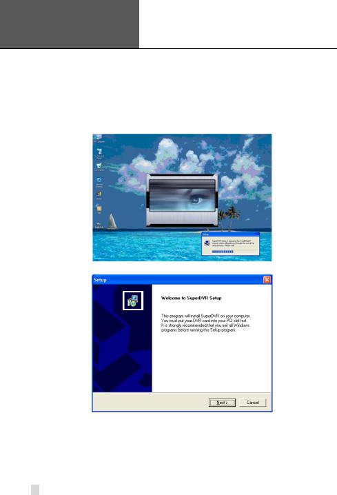
2.2 Install Video Capture Card Driver
STEP1 Run Setup.exe, and the installation interface appears as shown below:
Figure2-15H.264 Series Video Capture Card Installation Interface
Figure2-16 Welcome Page
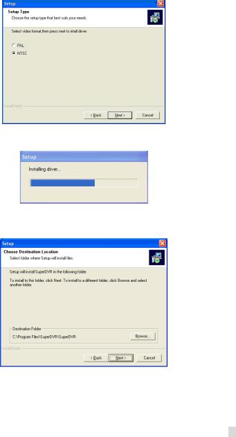
STEP2 Select video system, in the US we use NTSC format, click “next”
18
|
|
Error! Use the Home tab to apply |
|
|
|
1 to the text that you want to |
|
SuperDVR & H.264 Series Cards |
|
appear here. Error! Use the Home |
|
|
tab to apply 1 to the text that |
|
|
User Manual |
|
|
|
|
you want to appear here. |
|
Figure2-17Select Video Format
STEP3 Install driver first.
Figure2-18 Rate of Progress of Driver Installation
STEP4 After this process, it begins to install the application package SuperDVR, as shown below:
Figure2-19Select Installation Folder
19
Error! Use the Home tab to apply
1 to the text that you want to appear here. Error! Use the Home tab to apply 1 to the text that you want to appear here.
SuperDVR & H.264 Series Cards
User Manual
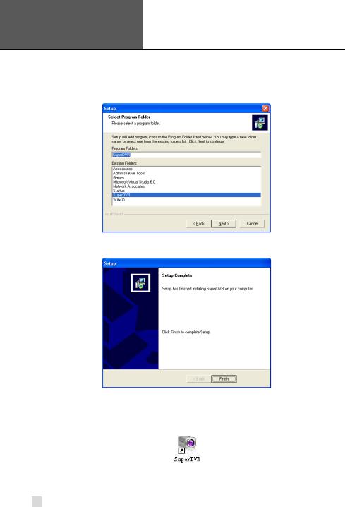
STEP5 Select a folder or use the default SuperDVR, and click ‘Next’.
Figure2-20Selecting program folder
STEP6 Click ‘Next’.
Figure2-21Driver and Application Installation Finished
STEP7 Click ‘Finish’.
STEP8 After all the processes are finished, it will create a shortcut on the desktop. Restart the computer and launch the surveillance program.
Figure2-22Shortcut of SuperDVR
NOTICE: When you install the driver software on Microsoft VISTA system, you need select the option shown below. Other steps of
20
|
|
Error! Use the Home tab to apply |
|
|
|
1 to the text that you want to |
|
SuperDVR & H.264 Series Cards |
|
appear here. Error! Use the Home |
|
|
tab to apply 1 to the text that |
|
|
User Manual |
|
|
|
|
you want to appear here. |
|
installing the driver software on Microsoft VISTA systems are the same as on Microsoft XP systems.
Figure2-23Installing the Software on VISTA
In cases where users cannot run the SuperDVR program, restart the computer.
You also need to disable the new user access control function in Vista. To do so:
Click on the Start button. Click on Control Panel Click on User Accounts
Click on the option to “Turn user account control on or off”
Click on the check mark in the box in front of “Use user account control to help protect your computer” to remove it.
Click on OK.
21
Error! Use the Home tab to apply
1 to the text that you want to appear here. Error! Use the Home tab to apply 1 to the text that you want to appear here.
SuperDVR & H.264 Series Cards
User Manual
3 Main Display Interface
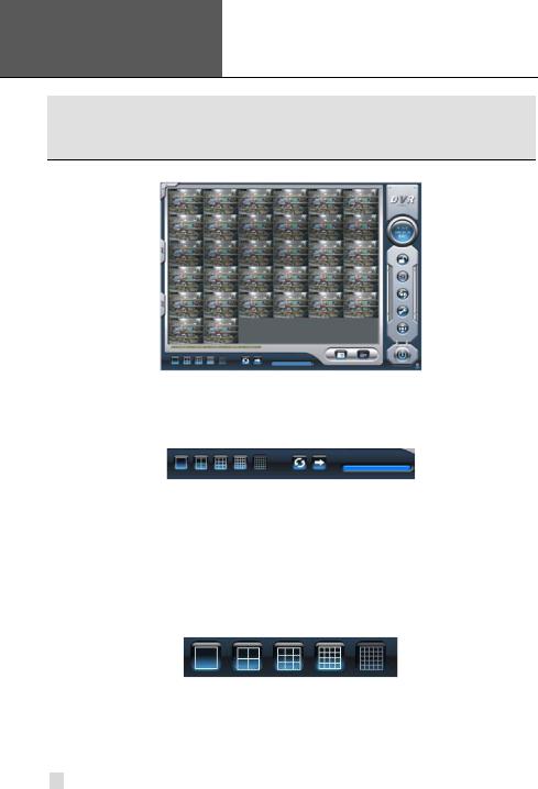
Run the SuperDVR program and the main display appears as shown below:
Figure3-1 SuperDVR Main Display Interface
3.1Display Control Panel
3.1.1Display Control Panel
Figure3-2 Display Control Panel
Display control panel includes Display Mode buttons, disk free space indicator, and ‘Auto Dwell’ button. Every button has its built-in indicator light. When you
switch the buttons on and off, the relative indicator lights turn on and off to indicate the working status.
NOTICE: Users can tell which buttons are working by the color of the buttons.
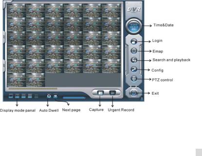
3.1.2 Display Modes
Figure3-3 Display Modes Panel
3.1.3 Flip Pages
When the display mode is 1CH, 4CH, 9CH, 16CH, click , system will display the next window according to the display mode.
22
|
|
Error! Use the Home tab to apply |
|
|
|
1 to the text that you want to |
|
SuperDVR & H.264 Series Cards |
|
appear here. Error! Use the Home |
|
|
tab to apply 1 to the text that |
|
|
User Manual |
|
|
|
|
you want to appear here. |
|
3.1.4 Auto Dwell Display Mode
If users want to see all the channels in sequence, then click  to enter Auto Dwell display mode.
3.1.5 Capture
If users want to capture a picture from the screen they can click  , the system will save 32 pictures to the default folder on the disk, c:\ path.
3.1.6 Urgent Record
Click  , system will be record and save all the cameras.
3.2 Login
Click  , and the login window appears. Input the user name and password, the default user name is ‘SYSTEM’ with no password, users will then access the main interface. Users can change password for SYSTEM and create new user names and passwords once they have entered the system.
Figure3-4 Main Interface
23
Error! Use the Home tab to apply
1 to the text that you want to appear here. Error! Use the Home tab to apply 1 to the text that you want to appear here.
SuperDVR & H.264 Series Cards
User Manual
3.3 Record
3.3.1 Record Modes
According to different record triggering methods, video capture cards offer users 4 different record modes:
•Schedule record mode (timer)
•Manual record mode
•Motion Detection record mode
•Sensor Alarm record mode
Motion Detection record mode and Sensor Alarm record mode are called Alarm Record.
If users use multiple cameras to record, every camera works separately and the recorded files are also saved separately. The parameters, i.e. camera ID, record date/time, and record mode are all saved together with the recorded file.
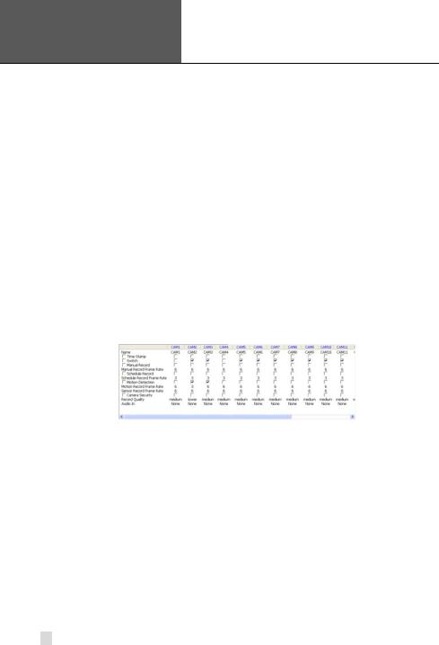
3.3.2 Record Setup
Figure3-5 Record Configuration Panel
In the ‘Record Panel’ of the Basic Configuration page, users can set all the necessary parameters for recording.
1.Time Stamp
By selecting this option, the record date / time message appears in the recorded file images.
2.Switch
By selecting this option, users can turn on corresponding cameras. If there is no camera on a channel, do not select this option and you will save system resources.
3.Manual Record
By selecting this option, the images from the selected camera will be recorded and saved all the time (24 hour recording).
24

|
|
Error! Use the Home tab to apply |
|
|
|
1 to the text that you want to |
|
SuperDVR & H.264 Series Cards |
|
appear here. Error! Use the Home |
|
|
tab to apply 1 to the text that |
|
|
User Manual |
|
|
|
|
you want to appear here. |
|
4.Manual Recording Frame Rate
Select the recording frame rate for manual record mode.
5.Schedule Record
This option allows you to record on a set schedule.
6.Schedule Record Frame Rate Select Schedule Recording frame rate.
7.Motion Detection
By selecting this option, users can set the selected channels to record when motion is detected in front of the camera.
8.Motion Record Frame Rate
Select recording frame rate for Motion Detection record mode.
9.Sensor Record Frame Rate
If sensors are utilized to trigger recording, users can select recording frame rate here.
NOTICE: Users can select more than one record mode.
10. Camera Security
Users are divided into three types: Normal user, Power user and Administrator. By selecting this option, only administrators can see the selected channels.
11. Record Quality
Select recording image quality here.
12. Audio in
SuperDVR 6.0 can support one channel of microphone audio input signal on the PC motherboard and any audio inputs that are on the card if any. Users can choose one video channel for each available audio input.
3.3.3 Record Status Panel
Figure3-6 Record Status Panel & Alarm Output Status Panel
Meanings of indicator light colors in row one are shown below:
• Grey light: Normal State
• Light Green light: Manual Record State
• Dark Green light: Schedule Record State
• Yellow light: Motion Detection Record State
25

Error! Use the Home tab to apply
1 to the text that you want to appear here. Error! Use the Home tab to apply 1 to the text that you want to appear here.
SuperDVR & H.264 Series Cards
User Manual
• Red light: Sensor Alarm Record State
• Blue light: Video Loss State
When the indicator light color turns into red  in row two, it means there is an alarm output.
3.3.4 Manual Record Mode
Manual Record mode is the most commonly used recording mode. If a special event occurs, users can select this recording mode and record immediately.
NOTICE: You can select a high frame rate for a short time manual recording, while selecting a low frame rate for long time Scheduled Record.
3.3.5 Sensor Alarm Record Mode
Users can use sensors to trigger sensor alarm recording on relative channels.
At that time, the record status indicator light will turn red .
.
3.3.6 Motion Detection Record Mode
This will enable the system to detect image changes and begin to record by activating motion detection and motion alarm recording. For instance, somebody opens the door, and the system detects image changes from the camera and begins to record, then users can play back the recorded file and find out who opened the door. When there is no movement, the system will not record which saves system resources, and makes it easier to find recorded events. The indicator light color in the record status panel will be
yellow .
.
NOTICE: Users need to setup parameters in three places to enable motion detection recording.
•Select ‘Motion Detection’ for desired channels in ‘Basic Configuration’.
•Configure the motion detection areas for desired channels in ‘Motion Detection Configuration’.
•Configure working schedule for desired channels in ‘Schedule Configuration’.
26

|
|
Error! Use the Home tab to apply |
|
|
|
1 to the text that you want to |
|
SuperDVR & H.264 Series Cards |
|
appear here. Error! Use the Home |
|
|
tab to apply 1 to the text that |
|
|
User Manual |
|
|
|
|
you want to appear here. |
|
3.3.7 Schedule Recording
Users can set working schedule for all of the recording modes in ‘Schedule
Configuration’. The dark green light  in record status panel shows the corresponding channel is in Schedule Record mode. Users can change
record mode to manual record at any time, and the dark green light  will
will
change into a light green light  .
.
Please refer to ‘4.4 Schedule Configuration’ for details.
3.3.8 Recycling Recordings
If users enable the Recycling Record function and all the selected HDD partitions are full, the oldest recorded data will be overwritten by the latest recorded data.
Users can set recording storage sequence for HDD partitions. The recording storage will automatically jump to the next partition when the current one is full. If all the partitions are full and recycling record mode has been enabled, the new data will overwrite the oldest recorded data automatically. Users can also set a HDD minimum storage alarm. Then once the present storage space is less than the minimum storage needed, and recycling record mode has not been enabled, the recording will automatically stop.
27
Error! Use the Home tab to apply
1 to the text that you want to appear here. Error! Use the Home tab to apply 1 to the text that you want to appear here.
SuperDVR & H.264 Series Cards
User Manual
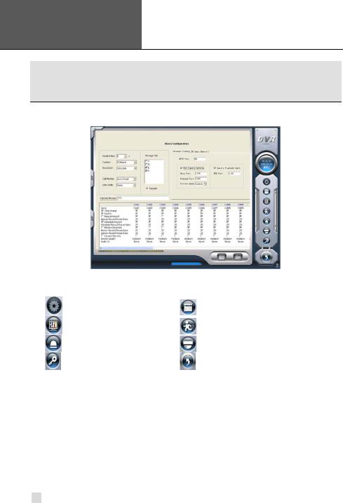
4 System Setup
Click  to enter the main setup interface.
Figure4-1 Basic Configuration
The definitions of the buttons in Figure4-1 are shown below:
Basic Configuration |
Schedule configuration |
Video configuration |
Motion Detection Configuration |
Alarm Configuration |
P.T.Z Configuration |
User Configuration |
Save and Return |
4.1 Basic Configuration
Click  to enter the basic configuration page where users can setup the system, or just use the defaults.
28
|
|
Error! Use the Home tab to apply |
|
|
|
1 to the text that you want to |
|
SuperDVR & H.264 Series Cards |
|
appear here. Error! Use the Home |
|
|
tab to apply 1 to the text that |
|
|
User Manual |
|
|
|
|
you want to appear here. |
|
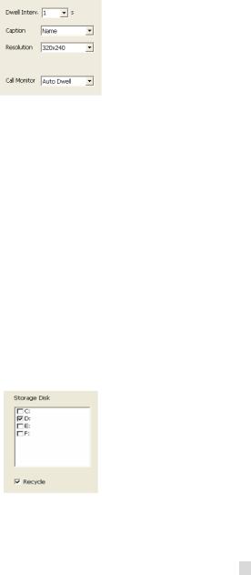
Figure4-2 Caption and General Configuration
1.Dwell Interval.
If users enable Auto Dwell function on the main interface page, users can set the dwell time, in seconds, of a screen here.
2.Caption
There are four options, None, ID, Name, and ID/Name for users to select for all the channels.
•‘None’ means no title or name;
•‘ID’ means camera numbers, i.e. 1, 2, 3 and so on;
•‘Name’ means camera names, i.e. Cam1, Cam2 and so on;
•‘ID/Name’ means both camera number and camera name, i.e. 1/Cam1, 2/Cam2 and so on.
3. Resolution
There is one resolution option, 320×244 for users to select for all the channels.
4.Call Monitor
Users can connect another monitor to the card and select the display modes here.
The following area is for your recording data storage area. Please see section 3.3.8.
Figure4-3 Record Data Storage Precept
SuperDVR shows all the available HDD partitions for users. Users can select one or more of the partitions that will be used in sequence from top to bottom. Please refer to section 3.3.8 to learn more about recycling records.
29

Error! Use the Home tab to apply
1 to the text that you want to appear here. Error! Use the Home tab to apply 1 to the text that you want to appear here.
SuperDVR & H.264 Series Cards
User Manual
In the following area in the basic configuration page, users can input the computer user name and password in the relative boxes. Then when restarting the computer system, it will give access to the system with the user name and password that was put in the boxes.
Figure4-4 Computer System Reboot Setup
Since the windows system may become unstable after a couple of days of continuous operating, it may cause SuperDVR to become unstable. You can use the software support auto-reboot option to help avoid this. Select  and set the interval by day, which will guide the system to reboot automatically according to the setup.
5.Capture browse
This item is the save path for captured files
Users can fill in the specific save path for their captured pictures. Click  to return to the main display interface.
4.2 Video Configuration
Click  and enter the video configuration page as shown below. Users can change the values of corresponding items, i.e. contrast, brightness, hue, saturation, auto gain, by moving the levers on the bars. Click ‘Default’, and all the values will return to the default value.
30
Loading...