


 Loading...
QSC Audio ISA 450, ISA 500Ti, ISA 280, ISA 800Ti, ISA 300Ti User Manual 2
...
Installed Sound Professional Audio Amplifiers
•ISA 280
•ISA 450
•ISA 750
•ISA 1350
•ISA 300Ti
•ISA 500Ti
•ISA 800Ti
User Manual |
EN |
|
|
Manual del Usario |
ES |
|
|
Manuel de l’utilisateur |
FR |
Bedienhandbuch DE
CH
*TD-000136-00* |
TD-000136-00 Rev.B |
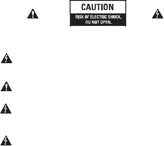
Important Safety Precautions & Explanation of Symbols
CAUTION: TO REDUCE THE RISK OF ELECTRIC SHOCK, DO NOT REMOVE THE COVER. NO USER-SERVICEABLE PARTS INSIDE. REFER SERVICING TO QUALIFIED PERSONNEL.
The lightning flash with arrowhead symbol within an equilateral triangle is intended to alert the user to the presence of uninsulated “dangerous” voltage within the product's
EN enclosure that may be of sufficient magnitude to constitute a risk of electric shock to humans.
The exclamation point within an equilateral triangle is intended to alert the user to the presence of important operating and maintenance (servicing) instructions in this manual.
The lightning flashes printed next to the OUTPUT terminals of the amplifier are intended to alert the user to the risk of hazardous energy. Output connectors that could pose a risk are marked with the lightning flash. Do not touch output terminals while amplifier power is on. Make all connections with amplifier turned off.
WARNING: To prevent fire or electric shock, do not expose this equipment to rain or moisture.
This amplifier has a serial number located on the rear panel.
Please write this and the model number down and keep them for your records.
Keep your purchase receipt. It is your proof of purchase.
Serial Number:______________________________
Date of Purchase:____________________________
Purchased From:_____________________________
© Copyright 2003, QSC Audio Products, Inc.
QSC® is a registered trademark of QSC Audio Products, Inc.
“QSC” and the QSC logo are registered with the U.S. Patent and Trademark Office All trademarks are the property of their respective owners.
2
Introduction
Thank you for purchasing this QSC power amplifier. Please read the following directions to obtain the best results.
Key Features:
•ISA 280, 450, 750, and 1350 models: 2 channels at 2 ohms (min.) impedance, bridgeable into 4 ohms (min.) impedance.
•ISA “Ti” models: low impedance outputs and isolated 70V or 100V for distributed audio systems, bridgeable for 140V and 200V. •QSC DataPort V2 connects to optional QSC signal processing accessories and amplifier monitoring systems.
•Mode switches Stereo, Bridge Mono, and Parallel Input operation.
• Independent Clip Limiter and Low Frequency Filter settings for each channel. •ISA 1350 equipped with front panel Protect mode LED indicator.
•QSC durability and performance.
EN
|
|
|
|
|
|
|
|
|
|
|
|
|
|
|
|
|
|
|
|
|
|
|
|
|
|
|
|
|
|
|
|
|
|
|
|
|
|
|
|
|
|
|
|
|
|
|
|
|
|
|
|
|
|
|
|
|
|
|
|
|
|
|
|
|
|
|
|
|
|
|
|
|
|
|
|
|
|
|
|
|
|
|
|
|
|
|
|
|
|
|
|
|
|
|
|
|
|
|
|
|
|
|
|
|
|
|
|
|
|
|
|
|
|
|
|
|
|
|
|
|
|
|
|
|
|
|
|
|
|
|
|
|
|
|
|
|
|
|
|
|
|
|
|
|
|
|
|
|
|
|
|
|
|
|
|
|
|
|
|
|
|
|
|
|
|
|
|
|
|
|
|
|
|
|
|
|
|
|
|
|
|
|
|
|
|
|
|
|
|
|
|
|
|
|
|
|
|
|
|
|
|
|
|
|
|
|
|
|
|
|
|
|
|
|
|
|
|
|
|
|
|
|
|
|
|
|
|
|
|
|
|
|
|
|
|
|
|
|
|
|
|
|
|
|
|
|
|
|
|
|
|
|
|
|
|
|
|
|
|
|
|
|
|
|
|
|
|
|
|
|
|
|
|
|
|
|
|
|
|
|
|
|
|
|
|
|
|
|
|
|
|
|
|
|
|
|
|
|
|
|
|
|
|
|
|
|
|
|
|
|
|
|
|
|
|
|
|
|
|
|
|
|
|
|
|
|
|
|
|
|
|
|
|
|
|
|
|
|
|
|
|
|
|
|
|
|
|
|
|
|
|
|
|
|
|
|
|
|
|
|
|
|
|
|
|
|
|
|
|
|
|
|
|
|
|
|
|
|
|
|
|
|
|
|
|
|
|
|
|
|
|
|
|
|
|
|
|
|
|
|
|
|
|
|
|
|
|
|
|
|
|
|
|
|
|
|
|
|
|
|
|
|
|
|
|
|
|
|
|
|
|
|
|
|
|
|
|
|
|
|
|
|
|
|
|
|
|
|
|
|
|
|
|
|
|
|
|
|
|
|
|
|
|
|
|
|
|
|
|
|
|
|
|
|
|
|
|
|
|
|
|
|
|
|
|
|
|
|
|
|
|
|
|
|
|
|
|
|
|
|
|
|
|
|
|
|
|
|
|
|
|
|
|
|
|
|
|
|
|
|
|
|
|
|
|
|
|
|
|
|
|
|
|
|
|
|
|
|
|
|
|
|
|
|
|
|
|
|
|
|
|
|
|
|
|
|
|
|
|
|
|
|
|
|
|
|
|
|
|
|
|
|
|
|
|
|
|
|
|
|
|
|
|
|
|
|
|
|
|
|
|
|
|
|
|
|
|
|
|
|
|
|
|
|
|
|
|
|
|
|
|
|
|
|
|
|
|
|
|
|
|
|
|
|
|
|
|
|
|
|
|
|
|
|
|
|
|
|
|
|
|
|
|
|
|
|
|
|
|
|
|
|
|
|
|
|
|
|
|
|
|
|
|
|
|
|
|
|
|
|
|
|
|
|
|
|
|
|
|
|
|
|
|
|
|
|
|
|
|
|
|
|
|
|
|
|
|
|
|
|
|
|
|
|
|
|
|
|
|
|
|
|
|
|
|
|
|
|
|
|
|
|
|
|
|
|
|
|
|
|
|
|
|
|
|
|
|
|
|
|
|
|
|
|
|
|
|
|
|
|
|
|
|
|
|
|
|
|
|
|
|
|
|
|
|
|
|
|
|
|
|
|
|
|
|
|
|
|
|
|
|
|
|
|
|
|
|
|
|
|
|
|
|
|
|
|
|
|
|
|
|
|
|
|
|
|
|
|
|
|
|
|
|
|
|
|
|
|
|
|
|
|
|
|
|
|
|
|
|
|
|
|
|
|
|
|
|
|
|
|
|
|
|
|
|
|
|
|
|
|
|
|
|
|
|
|
|
|
|
|
|
|
|
|
|
|
|
|
|
|
|
|
|
|
|
|
|
|
|
|
|
|
|
|
|
|
|
|
|
|
|
|
|
|
|
|
|
|
|
|
|
|
|
|
|
|
|
|
|
|
|
|
|
|
|
|
|
|
|
|
|
|
|
|
|
|
|
|
|
|
|
|
|
|
|
|
|
|
|
|
|
|
|
|
|
|
|
|
|
|
|
|
|
|
|
|
|
|
|
|
|
|
|
|
|
|
|
|
|
|
|
|
|
|
|
|
|
|
|
|
|
|
|
|
|
|
|
|
|
|
|
|
|
|
|
|
|
|
|
|
|
|
|
|
|
|
|
|
|
|
|
|
|
|
|
|
|
|
|
|
|
|
|
|
|
|
|
|
|
|
|
|
|
|
|
|
|
|
|
|
|
|
|
|
|
|
|
|
|
|
|
|
|
|
|
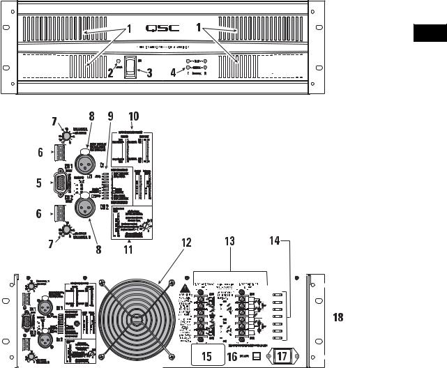
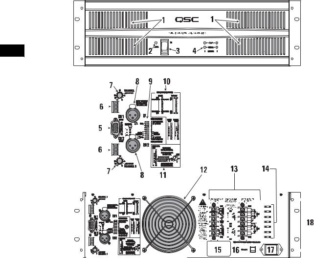
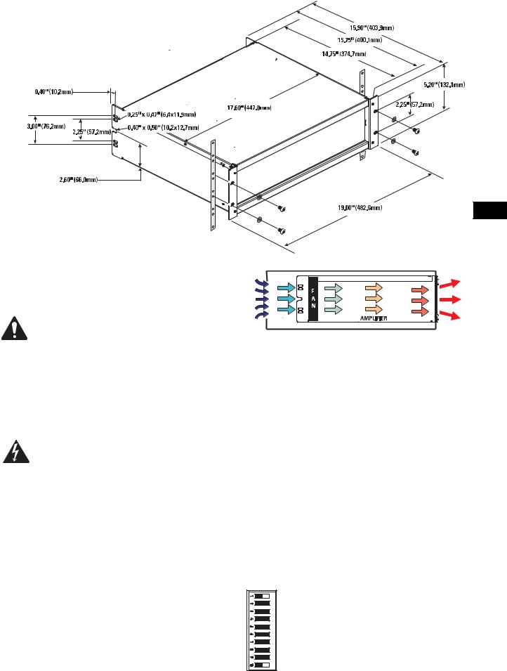
1- Cooling Air Exhaust Vents |
|
10Mode Switch Settings |
|||||||||||||||||||||||||||||||||||||||||||||
2- Power On Indicator (ISA 1350 has Protect LED also) |
|
11Bridge Mode Switch Settings and Notes |
|||||||||||||||||||||||||||||||||||||||||||||
3- Power Switch |
|
12Cooling Air Intake |
|||||||||||||||||||||||||||||||||||||||||||||
4- Clip and Signal Presence Indicators for each channel |
|
13Output Connectors (Ti model shown) |
|||||||||||||||||||||||||||||||||||||||||||||
5- DataPort V2 Connector |
|
14Tabs for Securing Output Wires |
|||||||||||||||||||||||||||||||||||||||||||||
6- Terminal block input connectors |
|
15Serial Number Decal |
|||||||||||||||||||||||||||||||||||||||||||||
7- Gain Controls |
|
16AC Power Circuit Breaker (ISA 1350 has two breakers) |
|||||||||||||||||||||||||||||||||||||||||||||
8- XLR input Connectors (locking) |
|
17IEC Power Connector |
|||||||||||||||||||||||||||||||||||||||||||||
9- Mode Switches (Clip Limiter, Operating Mode, Low-Frequency Filters) |
|
18Mounting Holes for Optional Handles |
|||||||||||||||||||||||||||||||||||||||||||||
Unpacking
Factory packed carton contains:
•the amplifier
•this User Manual
•IEC-type detachable power cord
•rear rack ear mounting kit
•3-pin terminal block connectors (2)
•rubber feet for non-rack mount installations (4)
Use the same type carton when shipping the amplifier.
3
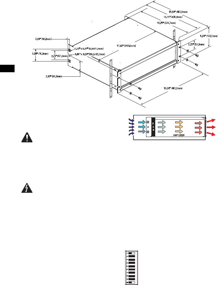
Rack Mounting
Use four screws and washers to mount the amplifier to the equipment rack rails. To use the amplifier outside a rack, attach the self-adhe- sive rubber feet to the bottom.
EN
Cooling
Air flows from the rack, into the back of the amplifier, and out the front. This keeps the rack cool. The fan automatically runs faster when the amp is working hard.
Do not block the rear intake or front air vents!
AC Mains
Connect AC power to the IEC socket on the back of the amplifier. NOTE: Turn off the AC power switch before connecting AC power.
The correct AC line voltage is shown on the serial number label, on the rear panel. Connecting to the wrong line voltage may damage the amplifier or increase the risk of electric shock.
Setting the Mode Switches
The rear panel mode switches control the amplifier’s operating mode, and each channel’s independent clip limiting and low frequency (LF) filtering. All models Clip Limiter switch settings are the same. However, Operating Mode and Low Frequency Filter settings are different for the Ti models. The rear panel label shows this information for convenient reference.
Air flow in QSC amplifiers: Cool air is drawn into the rear of the amplifier by the cooling fan. Warm air exits the front of the amplifier.
Setting Clip Limiters
Each channel has a clip limiter with its own on-off switch. The limiter only responds to actual clipping, and automatically compensates for load and voltage variations. Clip limiting is generally recommended, especially to protect high frequency drivers.
Switch 1 controls CH1. Switch 10 controls CH2.
Set switch to RIGHT to use Clip Limiting.
4
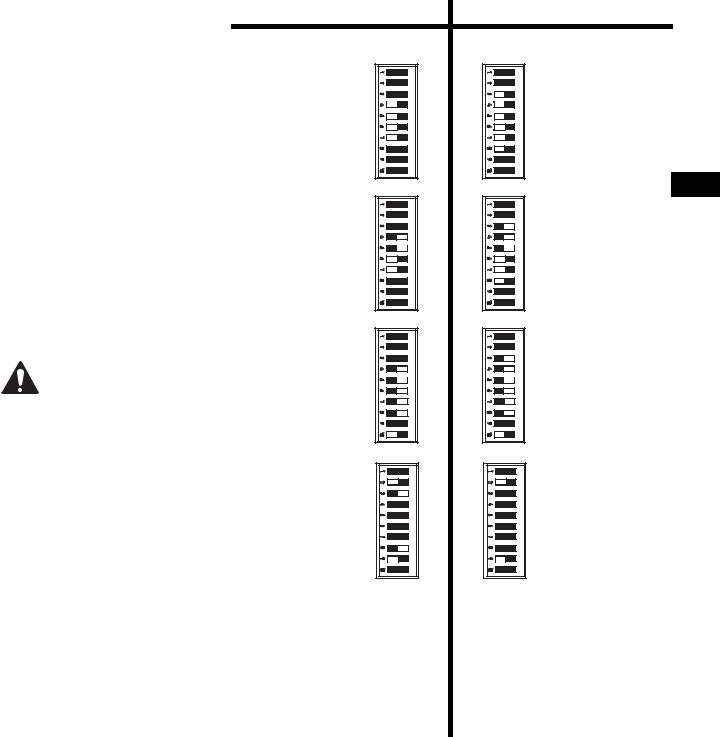
Selecting Stereo, Parallel, or Bridge Mode
The amplifier can be set for normal Stereo mode, Parallel Input mode, or Bridge Mono mode.
Stereo Mode- Each channel remains independent, and may be used for two different signals.
Parallel Mode - This setting connects both inputs together. One signal feeds both channels. Each channel's Gain control and speaker connection remain independent.
Bridge Mode- This setting combines both channels of a pair into a single channel with twice the output voltage. Use only the first channel's input and Gain control. Set the second channel's Gain control at minimum. The load must be rated for the higher power (or voltage) and is connected as shown on pages 6 and 7.
Do not connect more than one input when operating in parallel or bridge mode.
Setting Low Frequency Filters
ISA 280, ISA 450, ISA 750 and ISA 1350:
Use of the Low Frequency Filters is recommended. Use the appropriate switch settings to turn the filter ON or OFF and to select the filter frequency. When set to the ON position, the channel has a 12dB per octave Low Frequency filter to limit subaudio cone movement, making more power available for the loudspeaker’s rated frequency range. The filter should only be turned OFF for driving subwoofers.
ISA 300Ti, ISA 500Ti, and ISA 800Ti: The Low Frequency Filters are always active and not defeatable. Each channel has a 12dB per octave Low Frequency filter to prevent saturation of the 70V loudspeaker transformers. This reduces distortion and prevents amplifier overload. The 50 Hz setting usually works well with high quality loudspeaker transformers. The 75 Hz setting works well with speech-grade loudspeakers and transformers.
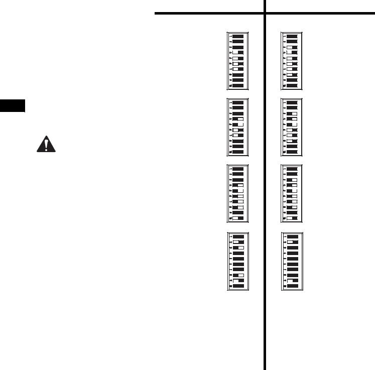
ISA 280/450/750/1350 |
ISA 300Ti/ 500Ti/800Ti |
Stereo Mode - |
Ti Stereo Mode - |
Switches 4, 5, 6 and 7 |
Switches 3, 4, 5, 6, 7, |
are all set to the LEFT |
and 8 are all set to the |
position. |
LEFT position. |
EN
Parallel Mode - |
Ti Parallel Mode - |
Switches 4 and 5 are |
Switches 3, 4, and 5 |
set to the RIGHT posi- |
are set to the RIGHT |
tion. |
position. |
Switches 6 and 7 are |
Switches 6, 7, and 8 |
set to the LEFT posi- |
are set to the LEFT |
tion. |
position. |
Bridge Mode- |
Ti Bridge Mode- |
Switches 4, 5, 6, 7, and |
Switches 3, 4, 5, 6, 7, |
8 are all set to the |
and 8 are all set to the |
RIGHT position. |
RIGHT position. |
Switch 10 is set to the |
Switch 10 is set to the |
LEFT position. |
LEFT position. |
Low Frequency Filter- |
Ti Low Frequency Filter- |
Switches 2 and 3 con- |
Switch 2 controls CH1. |
trol CH1. Switches 8 |
Switch 9 controls CH2. |
and 9 control CH2. |
Switches 2 and 9 select |
Switches 3 and 8 turn |
50Hz or 75 Hz. |
the LF filter ON or OFF. |
|
Switches 2 and 9 |
|
select 30Hz or 70 Hz. |
|
5
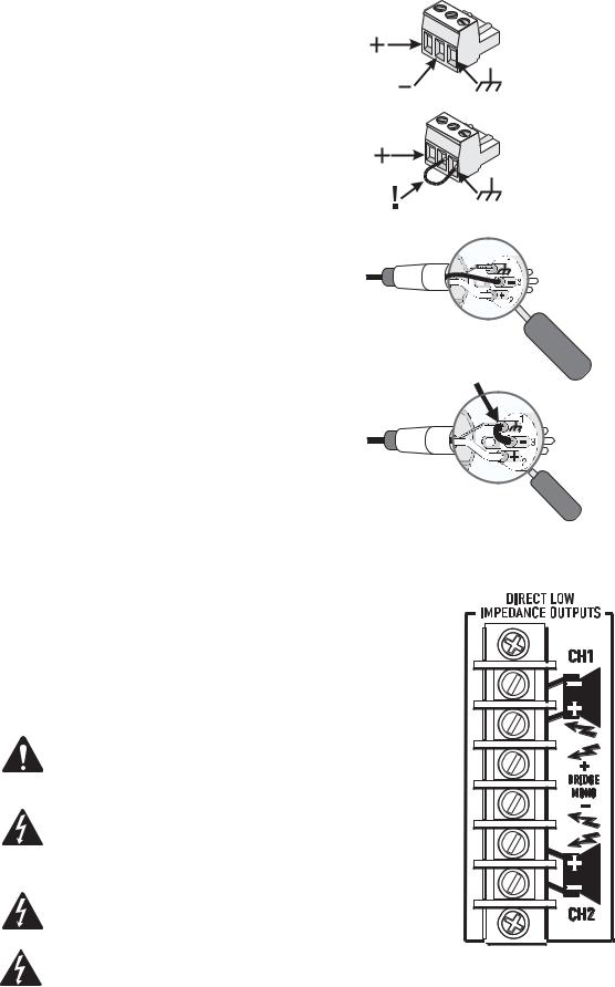
Inputs
|
Each channel has a balanced XLR and terminal block input. The |
|
input impedance is 20k ohm balanced or 10k ohm unbalanced. |
|
Balanced connections are recommended for less AC hum and |
|
interference, especially with long cable runs. Unbalanced con- |
|
nections may be suitable for short cables. The signal's source |
|
impedance should be less than 600 ohms. If the DataPort is |
|
being used to provide input signals to the amplifier, do not |
|
connect input signals to the XLR or terminal block connectors. |
|
If unbalanced connection is necessary, connect the signal con- |
|
ductor to the connector’s + pin and the shield to the ground |
EN |
pin. Connect a jumper between the ground pin and the - pin. |
|
|
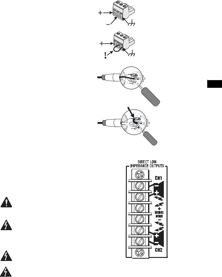
Direct Low Impedance Outputs
Direct Low Impedance Output connections are shown on the back of the chassis, to the right of the output terminals. Carefully note the polarity marks, which are arranged to make Bridge Mode connections easier.
Stereo and Parallel Mode- Connect each loudspeaker load to its own channel of the amplifier, as shown on the chassis label to the right of the terminals. The mode configuration switches, page 5, must be set for Stereo or Parallel mode.
Bridge Mode- Bridge mode configures the amplifier to drive a single, high power loudspeaker load. See page 5 to set the Bridge Mode switches. Connect the load as shown on label to the right of the terminals. Use the center two terminals labelled BRIDGE MONO. 4 ohms is the minimum impedance in bridged mode. Use Stereo or Parallel mode channels to drive 2 ohm loads.
BRIDGE MODE PRECAUTIONS: Do not use less than 4 ohm loads in bridge mode! 4 ohms is the minimum impedance for bridge mode operation.
OUTPUT TERMINAL SAFETY WARNING! Do not touch output terminals while amplifier power is on. Make all connections with amplifier turned off. Risk of hazardous energy!
WARNING! Risk of hazardous energy! Class 2 wiring shall be used.
ISA 1350 WARNING!: Use proper speaker wire. Class 2 wiring shall be used. For bridged mono mode, Class 3 wiring shall be used.
Balanced Terminal Block inputs: Strip the wire ¼ inch (6 mm) and connect to the plug as shown. Be sure to tighten the screws firmly.
Unbalanced Terminal Block inputs: Strip the wire ¼ inch and connect to the plug as shown. The middle pin must be connected to the shield pin as shown. Be sure to tighten the screws firmly.
Balanced XLR inputs: Connect to the plug as shown.
Unbalanced XLR inputs: Connect to the plug as shown. The - pin must be connected to the shield pin as shown.
Direct Low Impedance Outputs: Connect the loudspeakers as shown on the label next to the output terminals. Note Bridge Mono connection (center terminals) and polarity!
6
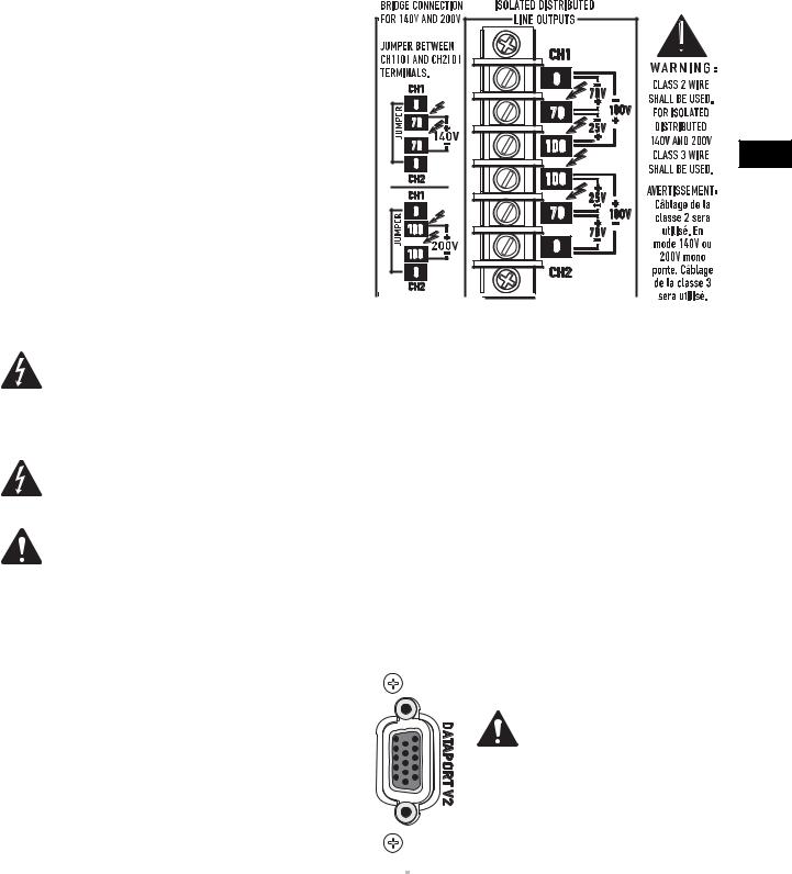
Isolated Distributed Line Outputs:
ISA 300Ti, ISA 500Ti, and ISA 800Ti
Models Only
Wiring connections are shown on the back of the chassis. STEREO and PARALLEL connections are shown on the right side of the terminals, and BRIDGE mode is shown on the left side. Carefully note the polarity marks, which are arranged to make Bridge Mode connections easier.
Stereo and Parallel Mode- Connect each 70V/100V circuit to its own channel of the amplifier, as shown on the label, right of terminals. The mode configuration switches, page 6, must be set for Stereo or Parallel mode.
Bridge Mode- Bridge mode configures the amplifier to drive a single 140V/200V audio circuit. See page 6 to set the Bridge Mode switches. Connect a jumper wire between CH1 [0] and CH2 [0] terminals.
Connect the load as shown on the label, left of the terminals. Connect only 140V/200V distributed audio circuits in bridged mode. Use Stereo or Parallel mode channels to drive 70V loads.
OUTPUT TERMINAL SAFETY WARNING! Do not touch output terminals while amplifier power is on. Make all connections with amplifier turned off. Risk of hazardous energy!
WARNING! Class 2 wire shall be used. For isolated distributed 140V and 200V, Class 3 wire shall be used.
ATTENTION! BRIDGE MODE CONNECTIONS: Connect a jumper wire between CH1 [0] and CH2 [0] terminals. The isolated output feature requires this jumper connection for bridge mode operation.
DataPort
The DataPort V2 connects to optional QSC accessories and processing devices. DataPort devices provide remote monitoring, DSP processing, filter and crossover functions.
Amplifier Standby is not supported.
If using the DataPort for input signals, do not use the Terminal Block or XLR inputs.
If the amplifier is being used in a system monitored through a QSC cinema monitor (or other QSC DataPort V2 supporting product) CH1 and CH2 output voltages and AC power status will be reported by the DataPort.
EN
70V/100V Stereo or Parallel connection: Each 70V/ 100V zone connects to its respective channel. Ensure that all speaker connections maintain proper polarity.
140V/200V Bridge connection: Wire each bridged pair to a 140V/200V circuit as shown. Connect a jumper wire between CH1 [0] and CH2 [0] terminals. Check for proper polarity.
DataPort V2 connector.
NOTE! If using the DataPort V2 connection for signal
input, the unused XLR or terminal block connectors may be used for daisy chaining the input signal to other amplifiers. However, note the signal will be 10 dB down from the signal applied to the DataPort.
7

LED Indicators
The LED indicators can be used to monitor system operation and identify common problems.
POWER: A single GREEN LED, on left side of AC Power switch.
Normal indication: AC switch ON: LED will illuminate.
If no indication: Check AC power cord and AC outlet.
CLIP: Two RED LEDs, one indicator for each channel.
|
Normal indication: illuminates whenever the amplifier is driven beyond full power. The resulting distor- |
|
tion corresponds to the brightness of the LED. Distortion that causes only brief flashing may not be audi- |
|
ble. |
EN |
During muting, the LED fully illuminates. This occurs during normal “On-Off” muting. |
|
|
|
Abnormal indication: |
|
Bright red illumination while the amp is being used indicates either thermal muting or a shorted output. |
|
If the amplifier overheats, the fan will run at full speed, and operation should resume within one minute. |
|
Allow the fan to run, and make sure the amplifier ventilation is adequate. |
|
A shorted or overloaded output circuit will cause excessive Clip flashing and possible overheating. |
|
If distortion is audible without a Clip indication, the problem is either before or after the amplifier. Check |
|
for damaged speakers or overloaded signal source. The amplifier Gain control should be in the upper half |
|
of its range to prevent input overload. |
|
SIGNAL: Two GREEN LEDs, one indicator for each channel. |
|
Normal indication: illuminates when the input signal is strong enough to drive the output to -40 dB from |
|
rated 8 ohm power. As signal approaches full power, the LED will illuminate continuously. |
|
If no indication: check Gain settings and increase gain if necessary. Check input connections and audio |
|
source for signal. If the Clip LED illuminates with little or no Signal indication, check the output wiring for |
|
shorts. |
|
Abnormal indication: If the Signal LED illuminates with no signal input, there may be system oscillations |
|
or some other malfunction. Disconnect the load and fully reduce the gain. If the signal LED remains on, the |
|
amp may need servicing. |
|
PROTECT (ISA 1350 only): A single RED LED directly below the POWER LED on left side of AC |
|
Power switch. |
|
Normal indication: not illuminated (NOTE!: If both rear panel AC circuit breakers are open, the PROTECT |
|
LED and the POWER ON LED will not illuminate) |
|
Abnormal indication: illuminated. If the PROTECT LED illuminates, the amplifier is in thermal protect or |
|
one of AC circuit breakers has opened. If the amplifier is hot, leave the AC power switch ON so that the fan |
|
cools the amplifier off. Normal operation will resume automatically after the amplifier has cooled suffi- |
|
ciently. If an AC circuit breaker (rear panel) has opened, reset the breaker by pushing inward on its reset |
|
button. |
|
Gain Controls |
|
Turn the gain controls clockwise to increase gain and counterclockwise to decrease gain. |
The Gain controls are marked in dB of attenuation. There are 11 detents for repeatable adjustments. The upper 6 steps are about 2 dB each, and settings should normally be made within this range. The range below -10 dB should not be used for normal program levels, as the input headroom could be exceeded, but can be used for testing at reduced levels. At the minimum setting, the signal is completely cut off.
The Gain controls can be adjusted by grasping the control shaft and rotating.
Power on indicator.
Clip and Signal indicators for both channels.
Gain controls are located on the rear panel.
8
Specifications (all models)
DYNAMIC HEADROOM |
2 dB at 4 ohms |
|
DISTORTION |
SMPTE-IM Less than 0.01% |
|
SIGNAL TO NOISE |
-100 dB (unweighted, 20 Hz.-20 kHz.) |
|
INPUT CLIPPING |
+22 dBu, 10 Vrms (ISA 1350: +15.3 dBu, 4.53 Vrms) |
|
INPUT IMPEDANCE |
10k ohms unbalanced, 20k ohms balanced |
|
AMPLIFIER PROTECTION |
Short circuit, open circuit, thermal, ultrasonic and RF protection. Stable into reactive or mismatched loads. |
|
LOAD PROTECTION |
Turn-on/turnoff muting, AC coupling (DC fault blocking), Clip limiting. |
|
COOLING |
Continuously variable speed fan; back-to-front air flow through heat sink tunnel |
EN |
|
||
LED INDICATORS |
POWER (green), SIGNAL (green, 1 per channel) and CLIP (red, 1 per channel) |
|
|
ISA 1350: also equipped with Protect LED (red) |
|
CONNECTORS |
Input: (2) 3-pin terminal block and (2) XLR |
|
|
Output: screw terminal barrier strip |
|
|
Control & Monitoring: (1) QSC DataPort V2 |
|
POWER REQUIREMENTS |
Refer to voltage specified on rear panel serial number label. Configured at factory for 100, 120 or 230 |
|
|
VAC, 5060 Hz. |
|
CONTROLS & INDICATORS |
Front: AC POWER switch |
|
|
Back: gain controls, 10-position DIP switch block (Clip Limiters, Stereo/Parallel/Bridge mode selection, |
|
|
Low frequency filter on/off (low impedance models only), Low frequency filter selection of 30/70 Hertz |
|
|
(low impedance models) or 50/75 Hertz (Ti models), and AC circuit breaker (2 breakers on ISA 1350). |
|
DIMENSIONS |
19.0" (48.3 cm) wide, 5.2" (13.2 cm) tall (3 rack spaces) 15.90" (40.4 cm) deep |
|
SPECIFICATIONS SUBJECT TO CHANGE WITHOUT NOTICE
9
Specifications: ISA 280, ISA 450, ISA 750, and ISA 1350
|
OUTPUT POWER in watts |
ISA280 |
ISA 450 |
ISA 750 |
ISA 1350 |
|
FTC: |
|
|
|
|
|
8 ohms, 2 channels driven |
185 |
260 |
450 |
800 |
|
(20 Hz - 20 kHz, 0.1% THD) |
|
|
|
|
|
4 ohms 2 channels driven |
280 |
400 |
650 |
1300 |
|
(20 Hz - 20 kHz, 0.1% THD) |
|
|
|
|
|
EIA: |
|
|
|
|
|
16 ohms, 1 channel driven |
100 |
140 |
250 |
475 |
|
(1 kHz, 0.1% THD) |
|
|
|
|
|
8 ohms, 1 channel driven |
200 |
280 |
475 |
850 |
|
(1 kHz, 0.1% THD) |
|
|
|
|
|
4 ohms, 1 channel driven |
300 |
450 |
750 |
1400 |
|
(1 kHz, 0.1% THD) |
|
|
|
|
|
2 ohms, 2 channels driven |
430 |
700 |
1200 |
2000 |
|
(1 kHz, 1.0% THD) |
|
|
|
|
EN |
|
|
|
|
|
Bridged Mono: |
|
|
|
|
|
|
|
|
|
|
|
|
16 ohms |
370 |
520 |
900 |
1600 |
|
(20 Hz - 20 kHz, 0.1% THD) |
|
|
|
|
|
8 ohms |
600 |
900 |
1500 |
2800 |
|
(1 kHz, 0.1% THD) |
|
|
|
|
|
4 ohms |
830 |
1400 |
2400 |
4000 |
|
(1 kHz, 1.0% THD) |
|
|
|
|
|
FREQUENCY RESPONSE |
+0.0, -1.0 dB: 20 Hz to 20 kHz (LF filter OFF, at -10 dB from rated power), -3 dB points: 5 Hz and 50 kHz. |
|||
|
DAMPING FACTOR |
>200 at 8 ohm load |
>200 at 8 ohm load |
>200 at 8 ohm load |
>250 at 8 ohm load |
|
INPUT SENSITIVITY |
+3.43 dBu (1.15 Vrms) |
+2.81 dBu (1.07 Vrms) |
+2.81 dBu (1.07 Vrms) |
+4.08 dBu (1.24 Vrms) |
|
VOLTAGE GAIN |
30.5 dB (33.4 x) |
33.0 dB (44.7 x) |
35.0 dB (56.2 x) |
36.1 dB (64.0x) |
|
OUTPUT CIRCUIT TYPE |
AB |
AB |
H 2-tier |
H 3-tier |
|
CURRENT CONSUMPTION (Ampere, rms, both channels driven, 120 VAC*) |
|
|
||
|
Idle |
0.5 |
0.5 |
0.6 |
1.3 |
|
1/8 power**, 8 ohms |
3.0 |
3.7 |
4.0 |
6.2 |
|
1/8 power**, 4 ohms |
4.5 |
6.0 |
6.3 |
9.9 |
|
1/8 power**, 2 ohms |
6.5 |
9.3 |
9.2 |
14.0 |
*NOTE: for 240 VAC models, multiply all values by 0.5 (one-half).
**NOTE: 1/8 power is representative of typical program material with occasional clipping.
WEIGHT |
36 pounds (20.0 kg) |
36 pounds (20.0 kg) |
47 pounds (25.0 kg) |
68 pounds (30.8 kg) |
SPECIFICATIONS SUBJECT TO CHANGE WITHOUT NOTICE
10
Specifications: ISA 300Ti, ISA 500Ti, and ISA 800Ti
OUTPUT POWER in watts |
ISA 300Ti |
ISA 500Ti |
ISA 800Ti |
|
FTC: |
|
|
|
|
8 ohms, 2 channels driven |
185 |
260 |
450 |
|
(20 Hz - 20 kHz, 0.1% THD) |
|
|
|
|
4 ohms 2 channels driven |
280 |
400 |
650 |
|
(20 Hz - 20 kHz, 0.1% THD) |
|
|
|
|
EIA: |
|
|
|
|
16 ohms, 1 channel driven |
100 |
140 |
250 |
|
(1 kHz, 0.1% THD) |
|
|
|
|
8 ohms, 1 channel driven |
200 |
280 |
475 |
|
(1 kHz, 0.1% THD) |
|
|
|
|
4 ohms, 1 channel driven |
300 |
450 |
750 |
|
(1 kHz, 0.1% THD) |
|
|
|
|
2 ohms, 2 channels driven |
430 |
700 |
1200 |
|
(1 kHz, 1.0% THD) |
|
|
|
|
|
|
|
EN |
|
Bridged Mono: |
|
|
|
|
|
|
|
|
|
16 ohms |
370 |
520 |
900 |
|
(20 Hz - 20 kHz, 0.1% THD) |
|
|
|
|
8 ohms |
600 |
900 |
1500 |
|
(1 kHz, 0.1% THD) |
|
|
|
|
4 ohms |
830 |
1400 |
2400 |
|
(1 kHz, 1.0% THD) |
|
|
|
|
Distributed High Impedance (per channel): |
|
|
|
|
70 Volt per channel |
300 |
500 |
800 |
|
(50 Hz - 16 kHz, 0.5% THD) |
|
|
|
|
100 Volt per channel |
300 |
500 |
800 |
|
(50 Hz - 16 kHz, 0.5% THD) |
|
|
|
|
140 Volt bridged, single channel |
600 |
1000 |
1600 |
|
(50 Hz - 16 kHz, 0.5% THD) |
|
|
|
|
200 Volt bridged, single channel |
600 |
1000 |
1600 |
|
(50 Hz - 16 kHz, 0.5% THD) |
|
|
|
|
FREQUENCY RESPONSE |
|
|
|
|
Direct Outputs |
-3.0, -0.5 dB: 50 Hz to 20 kHz (LF filter 50 Hz, 10 dB from rated power) |
|
|
|
Isolated Outputs |
+0.0, -3.0: 50 Hz to 16 kHz (LF filter 50 Hz, at -10 dB from rated power) |
|
|
|
OUTPUT REGULATION |
1.5 dB no-load to full-load |
|
|
|
INPUT SENSITIVITY |
|
|
|
|
Direct Low Impedance Outputs |
+3.43 dBu (1.15 Vrms) |
+2.81 dBu (1.07 Vrms) |
+2.81 dBu (1.07 Vrms) |
|
Isolated Distributed Line Outputs (Ti only) |
+2.20 dBu (1.00) Vrms) |
+1.80 dBu (0.95 Vrms) |
+1.80 dBu (0.95 Vrms) |
|
Full load, 70/100V |
|
|
|
|
VOLTAGE GAIN |
|
|
|
|
Direct Low Impedance Outputs |
30.5 dB (33.4 x) |
33.0 dB (44.7 x) |
35.0 dB (56.2 x) |
|
OUTPUT CIRCUIT TYPE |
AB |
AB |
H 2-tier |
|
CURRENT CONSUMPTION (Ampere, rms, both channels driven, 120 VAC*) |
|
|
|
|
Idle |
0.5 |
0.5 |
0.6 |
|
1/8 power**, 8 ohms |
3.0 |
3.7 |
4.0 |
|
1/8 power**, 4 ohms |
4.5 |
6.0 |
6.3 |
|
1/8 power**, 2 ohms |
6.5 |
9.3 |
9.2 |
|
1/8 power**, 70V/100V |
5.5 |
6.9 |
8.5 |
|
*NOTE: for 240 VAC models, multiply all values by 0.5 (one-half).
**NOTE: 1/8 power is representative of typical program material with occasional clipping.
WEIGHT |
44 pounds (20.0 kg) |
44 pounds (20.0 kg) |
55 pounds (25.0 kg) |
SPECIFICATIONS SUBJECT TO CHANGE WITHOUT NOTICE
11

Warranty Information & How To Contact QSC
Warranty (USA only; other countries, see your dealer or distributor)
Disclaimer
QSC Audio Products, Inc. is not liable for any damage to speakers, or any other equipment that is caused by negligence or improper installation and/or use of this amplifier product.
QSC Audio Products 3 Year Limited Warranty
QSC Audio Products, Inc. (“QSC”) guarantees its products to be free from defective material and / or workmanship for a period of three
(3) years from date of sale, and will replace defective parts and repair malfunctioning products under this warranty when the defect occurs under normal installation and use - provided the unit is returned to our factory or one of our authorized service stations via prepaid transportation with a copy of proof of purchase (i.e., sales receipt). This warranty provides that the examination of the return product must indicate, in our judgment, a manufacturing defect. This warranty does not extend to any product which has been subjected to
EN misuse, neglect, accident, improper installation, or where the date code has been removed or defaced. QSC shall not be liable for incidental and/or consequential damages. This warranty gives you specific legal rights. This limited warranty is freely transferable during the term of the warranty period.
Customer may have additional rights, which vary from state to state.
In the event that this product was manufactured for export and sale outside of the United States or its territories, then this limited warranty shall not apply. Removal of the serial number on this product, or purchase of this product from an unauthorized dealer, will void this limited warranty.
Periodically, this warranty is updated. To obtain the most recent version of QSC's warranty statement, please visit www.qscaudio.com.
Contact us at 800-854-4079 or visit our website at www.qscaudio.com.
How to Contact QSC Audio Products
Mailing address: QSC Audio Products, Inc. 1675 MacArthur Boulevard
Costa Mesa, CA 92626-1468 USA
Telephone Numbers: |
Main Number (714) 754-6175 |
|
Sales & Marketing (714) 957-7100 or toll free (USA only) (800) 854-4079 |
|
Customer Service(714) 957-7150 or toll free (USA only) (800) 772-2834 |
Facsimile Numbers: |
Sales & Marketing FAX(714) 754-6174 |
|
Customer Service FAX(714) 754-6173 |
World Wide Web: |
www.qscaudio.com |
E-mail: |
info@qscaudio.com |
|
service@qscaudio.com |
QSC Audio Products, Inc. 1675 MacArthur Boulevard Costa Mesa, California 92626 USA “QSC” and the QSC logo are registered with the U.S. Patent and Trademark Office.
©2003 QSC Audio Products, Inc.
12
Precauciones importantes de seguridad y explicación de los símbolos
PRECAUCIÓN: PARA REDUCIR EL RIESGO DE DESCARGA ELÉCTRICA, NO QUITE LA CUBIERTA. EL INTERIOR NO CONTIENE PIEZAS A LAS QUE EL USUARIO PUEDA DAR SERVICIO. REFIERA EL SERVICIO A PERSONAL CALIFICADO.
El símbolo del rayo con una punta de flecha dentro de un triángulo equilátero tiene la |
|
intención de alertar al usuario de la presencia de voltaje "peligroso" no aislado dentro de la |
|
caja del producto, que puede ser de magnitud suficiente para constituir un riesgo de |
|
descarga eléctrica a los seres humanos. |
|
ES |
|
El signo de exclamación dentro de un triángulo equilátero tiene la intención de alertar al |
|
usuario de la presencia de importantes instrucciones de operación y mantenimiento |
|
(servicio) en este manual. |
|
Los rayos impresos cerca de los terminales de SALIDA del amplificador tienen la intención |
|
de alertar al usuario del riesgo de energía peligrosa. Los conectadores de salida que |
|
pudiesen representar un riesgo están marcados con el símbolo del rayo. No toque los |
|
terminales de salida mientras el amplificador está encendido. Asegúrese de que todas las |
|
conexiones con el amplificador estén apagadas. |
|
ADVERTENCIA: Para prevenir incendios o descargas eléctricas, no exponga este equipo a |
|
la lluvia ni a la humedad. |
|
Este amplificador tiene un número de serie colocado en el panel posterior.
Por favor anote este número y el número de modelo y guárdelos para sus archivos.
Conserve su recibo de compra. Es el comprobante de su compra.
Número de serie:______________________________
Fecha de la compra:____________________________
Comprado en:_____________________________
© Derechos de autor 2003, QSC Audio Products, Inc.
QSC® es una marca comercial registrada de QSC Audio Products, Inc.
“QSC” y el logo QSC están registrados con la Oficina de Patentes y Marcas Comerciales de EE.UU. Todas las marcas comerciales son propiedad de sus respectivos dueños.
13
Introducción
Muchas gracias por la compra de este amplificador de potencia QSC. Por favor lea las siguientes instrucciones para obtener resultados óptimos.
Características clave:
•Modelos ISA 280, 450, 750 y 1350: 2 canales a 2 ohmios (mín.) de impedancia, puenteables a 4 ohmios (mín.) de impedancia. •Modelos ISA “Ti”: salidas de baja impedancia y aisladas de 70V o 100V para sistemas de audio distribuido, puenteables a 140V y 200V. •El QSC DataPort V2 se conecta a accesorios de procesamiento de señales y a sistemas de supervisión del amplificador QSC opcionales. •Conmutadores de modo de operación de entrada estéreo, monopuenteado y paralela.
•Limitador de recorte independiente y ajustes de filtro de baja frecuencia para cada canal.
•El modelo ISA 1350 está equipado con un indicador LED de modo de protección en el panel frontal. •La durabilidad y el rendimiento de QSC.
ES
|
|
|
|
|
|
|
|
|
|
|
|
|
|
|
|
|
|
|
|
|
|
|
|
|
|
|
|
|
|
|
|
|
|
|
|
|
|
|
|
|
|
|
|
|
|
|
|
|
|
|
|
|
|
|
|
|
|
|
|
|
|
|
|
|
|
|
|
|
|
|
|
|
|
|
|
|
|
|
|
|
|
|
|
|
|
|
|
|
|
|
|
|
|
|
|
|
|
|
|
|
|
|
|
|
|
|
|
|
|
|
|
|
|
|
|
|
|
|
|
|
|
|
|
|
|
|
|
|
|
|
|
|
|
|
|
|
|
|
|
|
|
|
|
|
|
|
|
|
|
|
|
|
|
|
|
|
|
|
|
|
|
|
|
|
|
|
|
|
|
|
|
|
|
|
|
|
|
|
|
|
|
|
|
|
|
|
|
|
|
|
|
|
|
|
|
|
|
|
|
|
|
|
|
|
|
|
|
|
|
|
|
|
|
|
|
|
|
|
|
|
|
|
|
|
|
|
|
|
|
|
|
|
|
|
|
|
|
|
|
|
|
|
|
|
|
|
|
|
|
|
|
|
|
|
|
|
|
|
|
|
|
|
|
|
|
|
|
|
|
|
|
|
|
|
|
|
|
|
|
|
|
|
|
|
|
|
|
|
|
|
|
|
|
|
|
|
|
|
|
|
|
|
|
|
|
|
|
|
|
|
|
|
|
|
|
|
|
|
|
|
|
|
|
|
|
|
|
|
|
|
|
|
|
|
|
|
|
|
|
|
|
|
|
|
|
|
|
|
|
|
|
|
|
|
|
|
|
|
|
|
|
|
|
|
|
|
|
|
|
|
|
|
|
|
|
|
|
|
|
|
|
|
|
|
|
|
|
|
|
|
|
|
|
|
|
|
|
|
|
|
|
|
|
|
|
|
|
|
|
|
|
|
|
|
|
|
|
|
|
|
|
|
|
|
|
|
|
|
|
|
|
|
|
|
|
|
|
|
|
|
|
|
|
|
|
|
|
|
|
|
|
|
|
|
|
|
|
|
|
|
|
|
|
|
|
|
|
|
|
|
|
|
|
|
|
|
|
|
|
|
|
|
|
|
|
|
|
|
|
|
|
|
|
|
|
|
|
|
|
|
|
|
|
|
|
|
|
|
|
|
|
|
|
|
|
|
|
|
|
|
|
|
|
|
|
|
|
|
|
|
|
|
|
|
|
|
|
|
|
|
|
|
|
|
|
|
|
|
|
|
|
|
|
|
|
|
|
|
|
|
|
|
|
|
|
|
|
|
|
|
|
|
|
|
|
|
|
|
|
|
|
|
|
|
|
|
|
|
|
|
|
|
|
|
|
|
|
|
|
|
|
|
|
|
|
|
|
|
|
|
|
|
|
|
|
|
|
|
|
|
|
|
|
|
|
|
|
|
|
|
|
|
|
|
|
|
|
|
|
|
|
|
|
|
|
|
|
|
|
|
|
|
|
|
|
|
|
|
|
|
|
|
|
|
|
|
|
|
|
|
|
|
|
|
|
|
|
|
|
|
|
|
|
|
|
|
|
|
|
|
|
|
|
|
|
|
|
|
|
|
|
|
|
|
|
|
|
|
|
|
|
|
|
|
|
|
|
|
|
|
|
|
|
|
|
|
|
|
|
|
|
|
|
|
|
|
|
|
|
|
|
|
|
|
|
|
|
|
|
|
|
|
|
|
|
|
|
|
|
|
|
|
|
|
|
|
|
|
|
|
|
|
|
|
|
|
|
|
|
|
|
|
|
|
|
|
|
|
|
|
|
|
|
|
|
|
|
|
|
|
|
|
|
|
|
|
|
|
|
|
|
|
|
|
|
|
|
|
|
|
|
|
|
|
|
|
|
|
|
|
|
|
|
|
|
|
|
|
|
|
|
|
|
|
|
|
|
|
|
|
|
|
|
|
|
|
|
|
|
|
|
|
|
|
|
|
|
|
|
|
|
|
|
|
|
|
|
|
|
|
|
|
|
|
|
|
|
|
|
|
|
|
|
|
|
|
|
|
|
|
|
|
|
|
|
|
|
|
|
|
|
|
|
|
|
|
|
|
|
|
|
|
|
|
|
|
|
|
|
|
|
|
|
|
|
|
|
|
|
|
|
|
|
|
|
|
|
|
|
|
|
|
|
|
|
|
|
|
|
|
|
|
|
|
|
|
|
|
|
|
|
|
|
|
|
|
|
|
|
|
|
|
|
|
|
|
|
|
|
|
|
|
|
|
|
|
|
|
|
|
|
|
|
|
|
|
|
|
|
|
|
|
|
|
|
|
|
|
|
|
|
|
|
|
|
|
|
|
|
|
|
|
|
|
|
|
|
|
|
|
|
|
|
|
|
|
|
|
|
|
|
|
|
|
|
|
|
|
|
|
|
|
|
|
|
|
|
|
|
|
|
|
|
|
|
|
|
|
|
|
|
|
|
|
|
|
|
|
|
|
|
|
|
|
|
|
|
|
|
|
|
|
|
|
|
|
|
|
|
|
|
|
|
|
|
|
|
|
|
|
|
|
|
|
|
|
|
|
|
|
|
|
|
|
|
|
|
|
|
|
|
|
|
|
|
|
|
|
|
|
|
|
|
|
|
|
|
|
|
|
|
|
|
|
|
|
|
|
|
|
|
|
|
|
|
|
|
|
|
|
|
|
|
|
|
|
|
|
|
|
|
|
|
|
|
|
|
|
|
|
|
|
|
|
|
|
|
|
|
|
|
|
|
|
|
|
|
|
|
|
|
|
|
|
|
|
|
|
|
|
|
|
|
|
|
|
|
|
|
|
|
|
|
|
|
|
|
|
|
|
|
|
|
|
|
|
|
|
|
|
|
|
|
|
|
|
|
|
|
|
|
|
|
|
|
|
|
|
|
|
|
|
|
|
|
|
|
|
|
|
|
|
|
|
|
|
|
|
|
|
|
|
|
|
|
|
|
|
|
|
|
|
|
|
|
|
|
|
|
|
|
|
|
|
|
|
|
|
|
|
|
|
|
|
|
|
|
|
|
|
|
|
|
|
|
|
|
|
|
|
|
|
|
|
|
|
|
|
|
|
|
|
|
|
|
|
|
|
|
|
|
|
|
|
|
|
|
|
|
|
|
|
|
|
|
|
|
|
|
|
|
|
|
|
|
|
|
|
|
|
|
|
|
|
|
|
|
|
|
|
|
|
|
|
|
|
|
|
|
|
|
|
|
|
|
|
|
|
|
|
|
|
|
|
|
|
|
|
|
|
|
|
|
|
|
|
|
|
|
|
|
|
|
|
|
|
|
|
|
|
|
|
|
|
|
|
|
|
|
|
|
|
|
|
|
|
|
|
|
|
|
|
|
|
|
|
|
|
|
|
|
|
|
|
|
|
|
|
|
|
|
|
|
|
|
|
|
|
|
|
|
|
|
|
|
|
|
|
|
|
|
|
|
|
|
|
|
|
|
|
|
|
|
|
|
|
|
|
|
|
|
|
|
|
|
|
|
|
|
|
|
|
|
|
|
|
|
|
|
|
|
|
|
|
|
|
|
|
|
|
|
|
|
|
|
|
|
|
|
|
|
|
|
1- Ventilas de descarga del aire de enfriamiento |
|
10Ajustes del conmutador de modo |
|||||||||||||||||||||||||||||||||||||||||||||||||||||||||||||||||||||
2- Indicador de encendido (el modelo ISA 1350 también tiene un LED de |
|
11Ajustes y notas del conmutador de modo puenteado |
|||||||||||||||||||||||||||||||||||||||||||||||||||||||||||||||||||||
protección) |
|
12Entrada del aire de enfriamiento |
|||||||||||||||||||||||||||||||||||||||||||||||||||||||||||||||||||||
3- Conmutador de encendido |
|
13Conectadores de salida (se muestra el modelo Ti) |
|||||||||||||||||||||||||||||||||||||||||||||||||||||||||||||||||||||
4- Indicadores de recorte y de presencia de señal para cada canal |
|
14Lengüetas para asegurar los cables de salida |
|||||||||||||||||||||||||||||||||||||||||||||||||||||||||||||||||||||
5- Conectador DataPort V2 |
|
15Calcomanía del número de serie |
|||||||||||||||||||||||||||||||||||||||||||||||||||||||||||||||||||||
6- Conectadores de entrada del bloque de terminales |
|
16Disyuntor de CA (el modelo ISA 1350 tiene dos disyuntores) |
|||||||||||||||||||||||||||||||||||||||||||||||||||||||||||||||||||||
7- Controles de ganancia |
|
17Conectador de potencia IEC |
|||||||||||||||||||||||||||||||||||||||||||||||||||||||||||||||||||||
8- Conectadores de entrada XLR (bloqueo) |
|
18Orificios de montaje para asas opcionales |
|||||||||||||||||||||||||||||||||||||||||||||||||||||||||||||||||||||
9- Conmutadores de modo (Limitador de recorte, Modo de operación, |
|
|
|
|
|
|
|
|
|
|
|
|
|
|
|
|
|
|
|
|
|
|
|
|
|
|
|
|
|
|
|||||||||||||||||||||||||||||||||||||||||
Filtros de baja frecuencia) |
|
|
|
|
|
|
|
|
|
|
|
|
|
|
|
|
|
|
|
|
|
|
|
|
|
|
|
|
|
|
|||||||||||||||||||||||||||||||||||||||||
Desembalaje
La caja empacada en fábrica contiene:
•el amplificador
•este Manual para el Usuario
•cable de alimentación desprendible tipo IEC
Cuando embarque el amplificador utilice el mismo tipo de caja.
•juego de montaje de orejeta de bastidor posterior
•conectadores de tres patas al bloque de terminales (2)
•patas de caucho para las instalaciones de montaje que no sean en bastidor (4)
14
Montaje en bastidor
Use cuatro tornillos y arandelas para montar el amplificador en los rieles del bastidor del equipo. Para usar el amplificador sin bastidor, instale las patas de caucho autoadhesivas en la parte inferior.
Enfriamiento
El aire fluye desde el bastidor hacia el interior por la parte posterior del amplificador y hasta afuera por la parte frontal. Este mantiene el bastidor frío. El ventilador automáticamente funciona más rápido cuando el amplificador está trabajando mucho.
¡No bloquee la toma posterior ni las aberturas de ventilación de la parte frontal!
Línea principal de CA
Conecte la CA en el receptáculo IEC que se encuentra en la parte posterior del amplificador. NOTA: Apague el conmutador de CA antes de conectar la CA.
El voltaje correcto de la línea de CA se muestra en la etiqueta del número de serie que se encuentra en el panel posterior. Si se conecta un voltaje de línea incorrecto se puede dañar el amplificador o aumentar el riesgo de una descarga eléctrica.
Ajuste de los conmutadores de modo
Los conmutadores de modo del panel posterior controlan el modo de operación del amplificador, y la limitación de recorte independiente y la filtración de baja frecuencia (LF) de cada canal. Los ajustes del conmutador limitador de recorte de todos los modelos son los mismos. Sin embargo, los ajustes de Modo de operación y de Filtro de baja frecuencia son diferentes para los modelos Ti. La etiqueta del panel posterior contiene esta información para su conveniente referencia.
Ajuste de los limitadores de recorte
Cada canal tiene un limitador de recorte con su propio conmutador de encendido y apagado. El limitador sólo responde al recorte real, y compensa automáticamente las variaciones de carga y de voltaje. Generalmente se recomienda la limitación de recorte, especialmente para proteger excitadores de alta frecuencia.
ES
Flujo de aire en los amplificadores QSC: El aire frío es arrastrado hacia el interior de la parte posterior del amplificador por el ventilador de enfriamiento. El aire caliente sale por el frente del amplificador.
El conmutador 1 controla CH1. El conmutador 10 controla CH2.
Ajuste el conmutador a la DERECHA para usar la limitación de recorte.
15
Selección del modo Estéreo, Paralelo o Puenteado
El amplificador se puede ajustar en modo estéreo normal, modo de entrada paralela o modo mono puenteado.
Modo estéreo: cada canal permanece independiente, y se puede usar para dos señales diferentes.
Modo paralelo: este ajuste conecta ambas entradas juntas. Una señal alimenta ambos canales. El control de ganancia y la conexión del altavoz de cada canal permanecen independientes.
Modo puenteado: este ajuste combina ambos canales de un par en un solo canal con dos veces el voltaje de salida. Use sólo la entrada y el control de ganancia del primer canal. Ajuste
ES el control de ganancia del segundo canal al mínimo. La carga debe estar clasificada para la potencia (o voltaje) mayor y está conectada como se muestra en las páginas 6 y 7.
No conecte más de una entrada cuando opere en modo paralelo o puenteado.
Ajuste de los filtros de baja frecuencia
Modelos ISA 280, ISA 450, ISA 750 e ISA 1350: Se recomienda el uso de los filtros de baja frecuencia. Use los ajustes apropiados del conmutador para ENCENDER y APAGAR el filtro y para seleccionar la frecuencia del filtro. Cuando se ajusta en la posición ENCENDIDO, el canal tiene un filtro de baja frecuencia de 12dB por octava para limitar el movimiento del cono del subaudio, liberando más potencia para la amplitud de frecuencia nominal del altavoz. El filtro sólo se debe APAGAR para los subwoofers excitadores.
Modelos ISA 300Ti, ISA 500Ti e ISA 800Ti:
Los filtros de baja frecuencia siempre están activos y no se pueden anular. Cada canal tiene un filtro de baja frecuencia de 12dB por octava para prevenir la saturación de los transformadores de 70V del altavoz. Esto reduce la deformación y evita la sobrecarga del amplificador. El ajuste de 50 Hz usualmente funciona bien con transformadores de amplificadores de alta calidad. El ajuste de 75 Hz funciona bien con altavoces y transformadores de calidad parlante.
ISA 280/450/750/1350 |
ISA 300Ti/ 500Ti/800Ti |
Modo estéreo: los |
Modo estéreo Ti - Los |
conmutadores 4, 5, 6 y 7 |
conmutadores 3, 4, 5, 6, 7 |
todos están ajustados en |
y 8 están todos |
la posición IZQUIERDA. |
ajustados en la posición |
|
IZQUIERDA. |
Modo paralelo - Los |
Modo paralelo Ti - Los |
conmutadores 4 y 5 están |
conmutadores 3, 4 y 5 |
ajustados en la posición |
están ajustados en la |
DERECHA. |
posición DERECHA. |
Los conmutadores 6 y 7 |
Los conmutadores 6, 7 y |
están ajustados en la |
8 están ajustados en la |
posición IZQUIERDA. |
posición IZQUIERDA. |
Modo puenteado - Los |
Modo puenteado Ti - Los |
conmutadores 4, 5, 6, 7 y 8 |
conmutadores 3, 4, 5, 6, |
están todos ajustados en |
7 y 8 están todos |
la posición DERECHA. |
ajustados en la posición |
El conmutador 10 está |
DERECHA. |
ajustado en la posición |
El conmutador 10 está |
IZQUIERDA. |
ajustado en la posición |
|
IZQUIERDA. |
Filtro de baja frecuencia- |
Filtro de baja frecuencia Ti- |
Los conmutadores 2 y 3 |
El conmutador 2 controla |
controlan CH1. Los |
CH1. |
conmutadores 8 y 9 |
El conmutador 9 controla |
controlan CH2. |
CH2. |
Los conmutadores 3 y 8 |
Los conmutadores 2 y 9 |
ENCIENDEN o APAGAN el |
seleccionan 50Hz ó 75 Hz. |
filtro LF. Los |
|
conmutadores 2 y 9 |
|
seleccionan 30Hz ó 70 Hz. |
|
16
Entradas
Cada canal tiene balance de audio XLR y una entrada al bloque de terminales. La impedancia de entrada es de 20k ohmios balanceada o 10k ohmios no balanceada.
Se recomiendan conexiones balanceadas para un menor zumbido e interferencia de la CA, especialmente en tramos largos de cable. Las conexiones no balanceadas pueden ser adecuadas para tramos cortos de cable. La impedancia de la fuente de la señal debe ser menor de 600 ohmios. Si el DataPort se está usando para proporcionar señales de entrada al amplificador, no conecte las señales de entrada al XLR ni a los conectadores del bloque de terminales.
Si es necesaria una conexión no balanceada, conecte el conductor de señal a la pata + del conectador y el blindaje a la pata de conexión a tierra. Conecte un puente entre la pata de conexión a tierra y la pata -.
Salidas directas de baja impedancia
Las conexiones directas a las salidas de baja impedancia se muestran en la parte posterior del chasis, a la derecha de los terminales de salida. Note detenidamente las marcas de polaridad, que están configuradas para facilitar las conexiones del modo puenteado.
Modo estéreo y paralelo: Conecte cada carga del altavoz a su propio canal del amplificador, como se muestra en la etiqueta del chasis que se encuentra a la derecha de los terminales. Los conmutadores de configuración de modo, página 5, deben ajustarse en modo estéreo o paralelo.
Modo puenteado: El modo puenteado configura el amplificador para que excite una sola carga de alta potencia del altavoz. Consulte la página 5 para ajustar los conmutadores de modo puenteado. Conecte las cargas como se muestra en las etiquetas a la derecha de los terminales. Use los dos terminales centrales marcados como BRIDGE MONO (MONOPUENTEADO). 4 ohmios es la impedancia mínima en el modo puenteado. Use los canales de modo estéreo o paralelo para excitar cargas de 2 ohmios.
PRECAUCIONES CON EL MODO PUENTEADO: ¡No use cargas menores de 4 ohmios en el modo puenteado! 4 ohmios es la impedancia mínima para la operación en modo puenteado.
¡ADVERTENCIA SOBRE LA SEGURIDAD DE LOS TERMINALES DE SALIDA! No toque los terminales de salida mientras el amplificador está encendido. Asegúrese de que todas las conexiones con el amplificador estén apagadas. ¡Riesgo de energía peligrosa!
¡ADVERTENCIA! ¡Riesgo de energía peligrosa! Se debe usar cableado Clase 2.
¡ADVERTENCIA DE ISA 1350!: Use el alambre adecuado para el altavoz. Se debe usar cableado Clase 2. Para el modo monopuenteado se debe usar cableado Clase 3.
Entradas balanceadas del bloque de terminales: quite 1/4 de pulgada (6 mm) de aislamiento del cable y conecte la clavija como se muestra. Asegúrese de apretar firmemente los tornillos.
Entradas no balanceadas del bloque de terminales: quite 1/4 de pulgada de aislamiento y conecte la clavija como se muestra La pata central debe estar conectada con la pata de blindaje como se muestra. Asegúrese de apretar firmemente los tornillos.
Entradas XLR balanceadas:
conecte a la clavija como se ES muestra.
Entradas XLR no balanceadas: conecte a la clavija como se muestra. La pata - debe estar conectada con la pata de blindaje como se muestra.
Salidas directas de baja impedancia: Conecte los altavoces como se muestra en la etiqueta que se encuentra junto a los terminales de salida. ¡Note la conexión monopuenteada (terminales centrales) y la polaridad!
17
Loading...