


AD-S82H
AcousticDesign Multi-Use Loudspeaker
AD-S82
AD-S82H
203 mm (8”) two-way
User Manual
Manual del Usario
Manuel de l’utilisateur
Bedienhandbuch
用户手册
EN
ES
FR
DE
CH
*TD-000115-00*
TD-000115-00 rev.D
EN
IMPORTANT SAFETY PRECAUTIONS
& EXPLANATION OF SYMBOLS
1- Read these instructions.
2- Keep these instructions.
3- Heed all warnings.
4- Follow all instructions.
5- Clean only with a dry cloth.
6- Install in accordance with QSC Audio Product’s instructions and a licensed, professional engineer.
7- Do not install near any heat sources such as radiators, heat registers, stoves, or other apparatus (including
amplifiers) that produce heat.
8- Only use attachments/accessories from QSC Audio Products, Inc.
9- Use only with mounts or brackets specified by QSC Audio Products.
10- Refer all servicing to qualified personnel. Servicing is required when the apparatus has been damaged in
any way.
The lightning flash with arrowhead symbol within an equilateral triangle is intended to alert the user to the
presence of uninsulated “dangerous” voltage within the product’s enclosure that may be of sufficient magnitude to constitute a risk of electric shock to humans.
The exclamation point within an equilateral triangle is intended to alert the user to the presence of important
operating and maintenance (servicing) instructions in this manual.
WARNING! Before placing, installing, rigging, or suspending any speaker product, inspect all hardware, suspension, cabinets, transducers, brackets and associated equipment for damage. Any missing, corroded,
deformed or non-load rated component could significantly reduce the strength of the installation, placement, or
array. Any such condition severely reduces the safety of the installation and should be immediately corrected.
Use only hardware which is rated for the loading conditions of the installation and any possible short-term
unexpected overloading. Never exceed the rating of the hardware or equipment. Consult a licensed, professional engineer when any doubt or questions arise regarding a physical equipment installation.
Warranty (USA only; other countries, see your dealer or distributor)
Disclaimer
QSC Audio Products, Inc. is not liable for any damage to amplifiers, or any other equipment that is caused by negligence or
improper installation and/or use of this loudspeaker product.
QSC Audio Products 3 Year Limited Warranty
QSC Audio Products, Inc. (“QSC”) guarantees its products to be free from defective material and / or workmanship for a period of
three (3) years from date of sale, and will replace defective parts and repair malfunctioning products under this warranty when the
defect occurs under normal installation and use - provided the unit is returned to our factory or one of our authorized service stations via pre-paid transportation with a copy of proof of purchase (i.e., sales receipt). This warranty provides that the examination
of the return product must indicate, in our judgment, a manufacturing defect. This warranty does not extend to any product which
has been subjected to misuse, neglect, accident, improper installation, or where the date code has been removed or defaced. QSC
shall not be liable for incidental and/or consequential damages. This warranty gives you specific legal rights. This limited warranty is freely transferable during the term of the warranty period.
Customer may have additional rights, which vary from state to state.
In the event that this product was manufactured for export and sale outside of the United States or its territories, then this limited
warranty shall not apply. Removal of the serial number on this product, or purchase of this product from an unauthorized dealer,
will void this limited warranty.
Periodically, this warranty is updated. To obtain the most recent version of QSC’s warranty statement, please visit www.qscaudio.com.
Contact us at 800-854-4079 or visit our website at www.qscaudio.com.
© Copyright 2003, 2005, QSC Audio Products, Inc.
QSC® is a registered trademark of QSC Audio Products, Inc.
“QSC” and the QSC logo are registered with the U.S. Patent and Trademark Office
All trademarks are the property of their respective owners.
2
Introduction
Thank you and congratulations on your purchase of the Acoustic Design AD-S82 Multi-Use, All-Weather Loudspeakers. These
products represent the state-of-the-art in all-weather, lightweight SR (sound reinforcement) loudspeaker systems. To get the most
from your investment, we encourage you to review this manual carefully.
The AD-S82 loudspeaker systems are full range, high output, two-way designs delivering superior sound quality and high SPL in a
lightweight, all-weather enclosure. These loudspeakers make an excellent choice for a wide variety of SR applications.
Coverage Angles
Before mounting the loudspeaker, determine the mounting orientation and desired coverage angles. As supplied from the factory,
the loudspeaker’s coverage angles are 90° (horizontal) x 60° (vertical) with the cabinet oriented vertically. The waveguide can be
rotated to interchange the coverage angles.
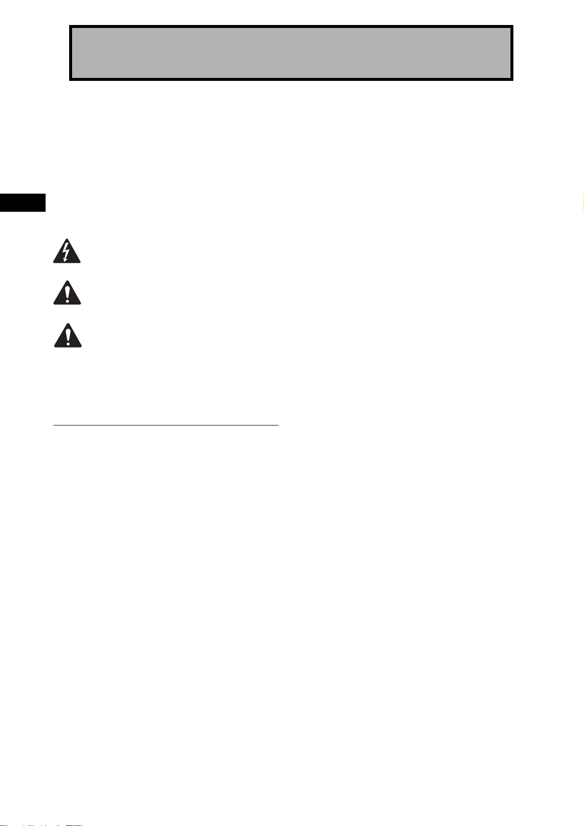
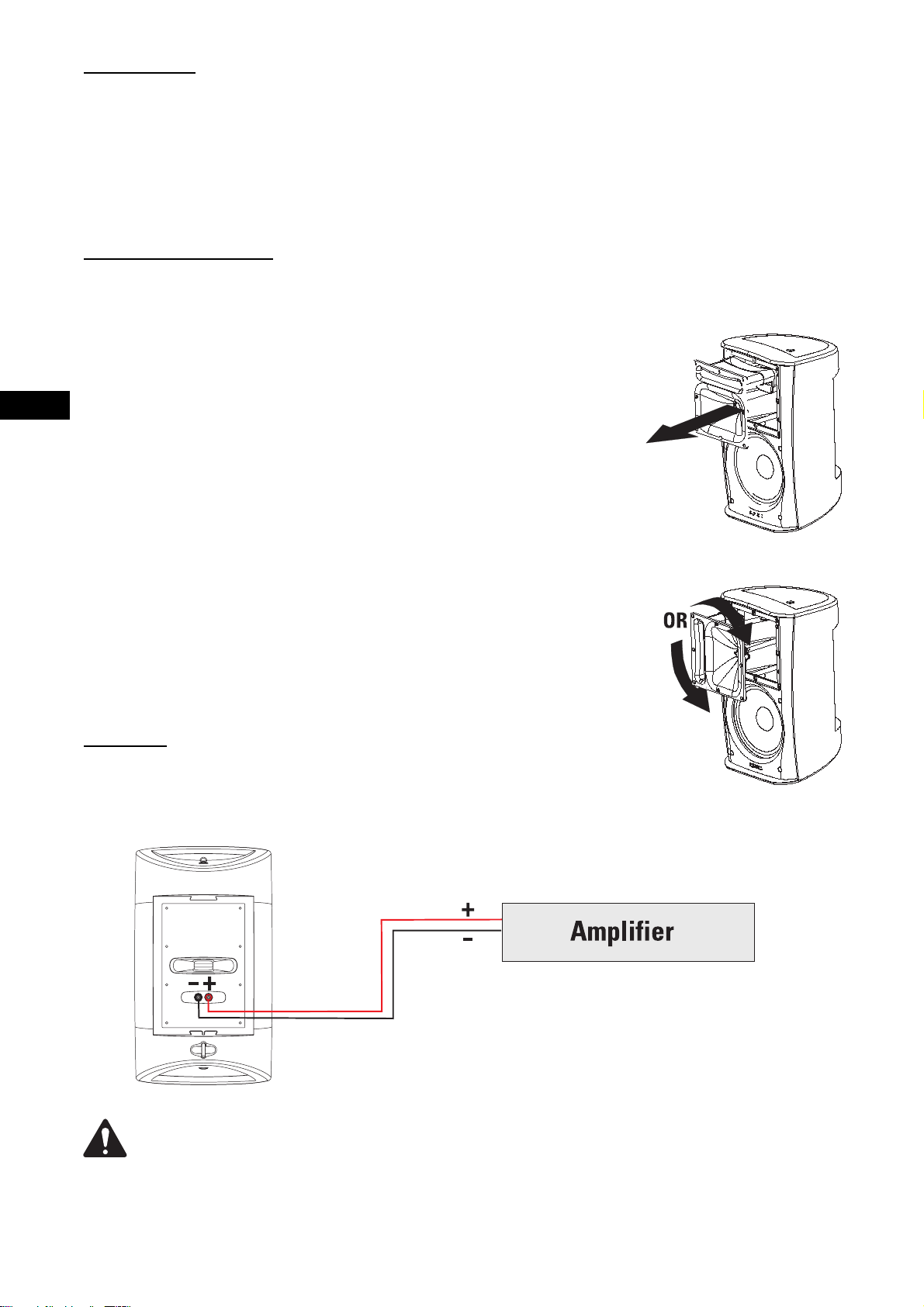
Rotating the Waveguide to Alter HF Coverage Pattern
1- Remove the grill. Gently and evenly work the grill out of its retaining groove to avoid bending
the grill.
2- Remove the eight waveguide retaining screws. A #2-size Phillips screwdriver is recommended.
3- Reach into the waveguide’s port and pull gently to remove the waveguide. Be careful not to
damage the connections, wiring, or the gasket between the waveguide and the cabinet.
EN
4- Rotate the horn 90° clockwise or counterclockwise and set it back in place. Make certain the
wiring is not stressed or pulled loose from its connections when rotating the assembly.
5- Before reinstalling the waveguide screws, lift the assembly a small distance and make sure
that the gasket is properly in place. Reposition it, if required. Set the waveguide in place and
install the screws. Do not overtighten.
6- Replace the grill.
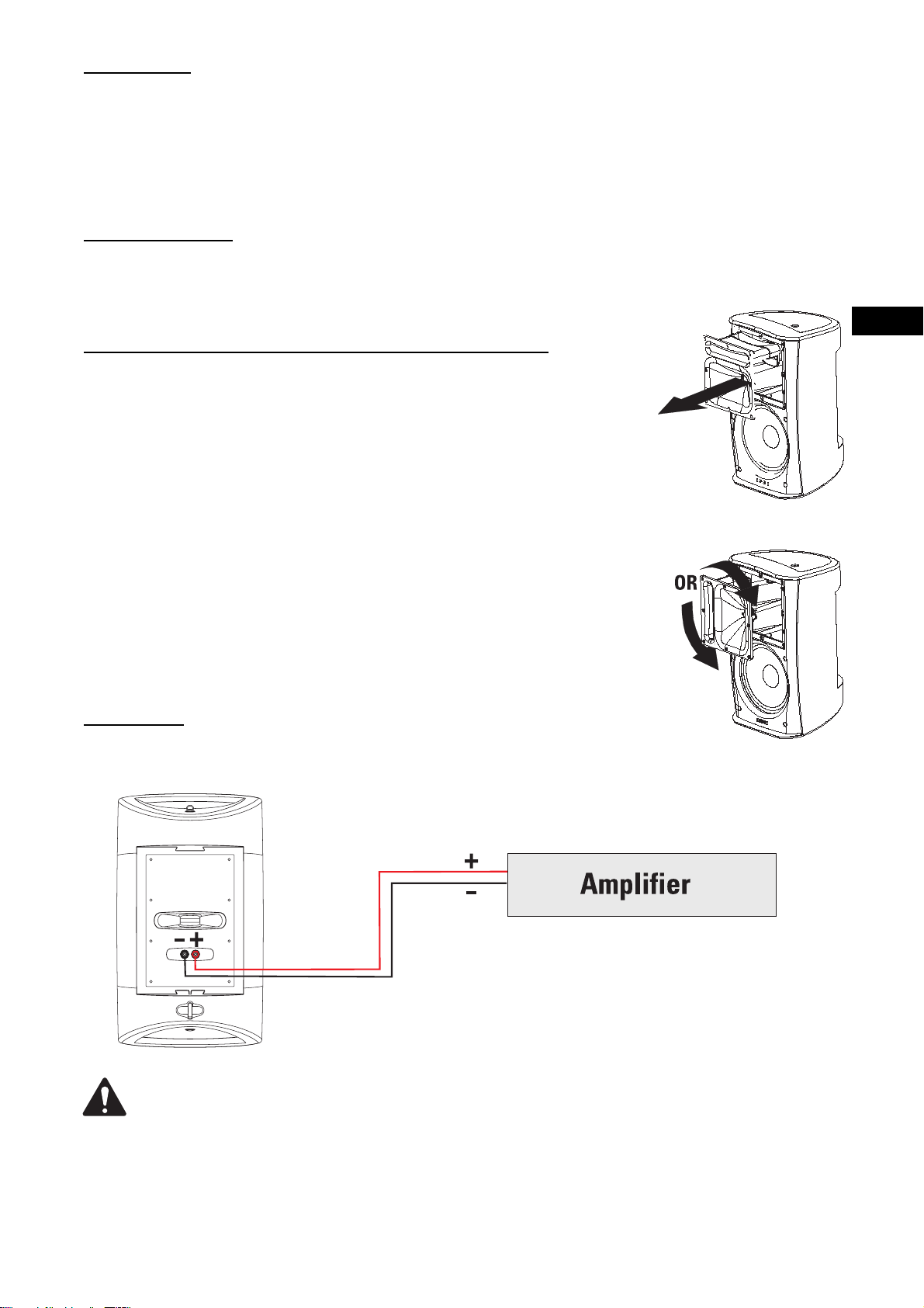
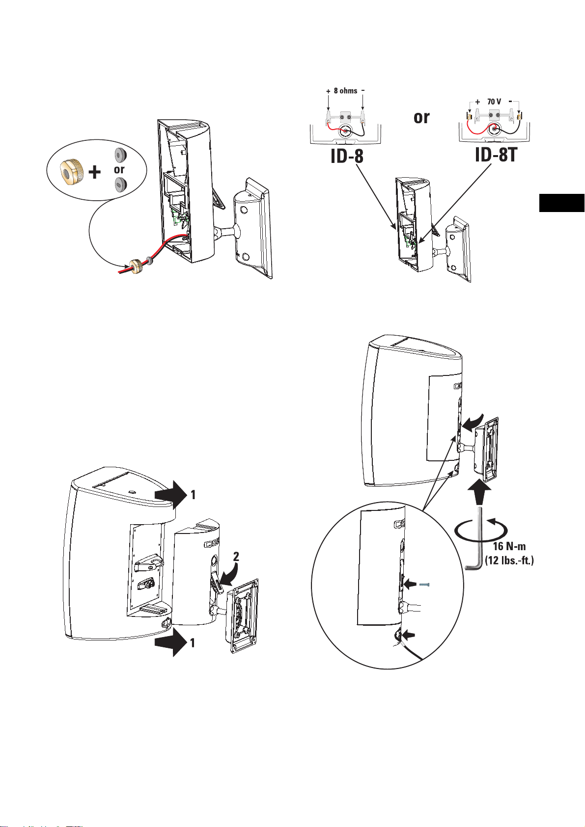
Connection
Connect the amplifier’s + and - outputs directly to the loudspeaker’s + (red) and - (black) terminals. If using optional ID-8 or YM-8 mounting hardware, refer to the instructions provided with the hardware.
Maintain proper speaker and amplifier connection polarity throughout the entire system. All positive-marked
loudspeaker terminals should be connected to positive-marked amplifier output terminals. This will provide the
best possible low-frequency output from your system.
3
Mounting
If using the loudspeaker only (no optional mount), the loudspeaker can be set on any appropriate surface. The cabinet will lean
back at a slight angle when set on a flat surface.
When operated at high output levels, the cabinet can generate sufficient vibration, causing the cabinet to move or creep if set on
a hard surface. Use anti-slip matting under the cabinet or self-adhesive rubber feet to keep the cabinet from creeping.
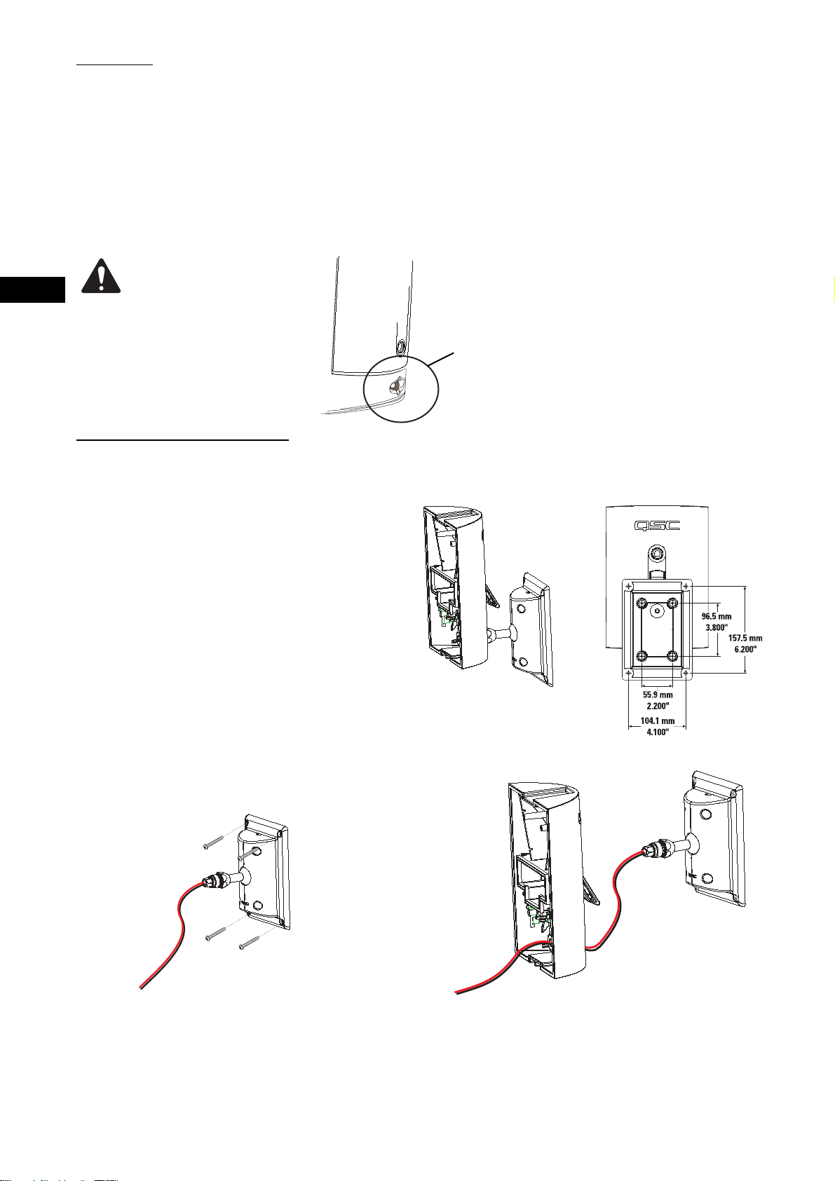
On the back of the loudspeaker, near the bottom, is a safety cable attachment point. Install a safety cable strong enough to support several times the weight of the loudspeaker assembly in the event it may fall. The cable must be secured to a secondary support point which is also strong enough to support several times the loudspeaker’s weight.
EN
IMPORTANT! ENSURE THAT THE
LOUDSPEAKER IS MOUNTED
PROPERLY AND A SAFETY
CABLE IS INSTALLED TO RETAIN THE
LOUDSPEAKER IN THE EVENT OF A
MOUNTING FAILURE.
Optional Mounts Available
ID-8 and ID-8T IntelliDock™ Mounts (YM-8 models, see p.6)
This mount features a quick-connect/disconnect latch which
provides electrical connections and a highly-adjustable balltype mount. This mount allows for all mounts and wiring to be
fully installed and the loudspeakers to be placed at the last
possible moment.
A security retaining screw for the latch in included, making
speaker removal impossible without the correct Allen (hex) bit
to remove the screw. The IntelliDock mount and its wiring
feed-through bushing provide maximum weather resistance
and maximum acoustic coverage range adjustment.
Ensure the mounting surface and supporting structure are appropriately strong enough to support the
loudspeaker assembly and any potential vibration or
seismic activity.
Attach a safety cable to the attachment point on the
bottom-back of the loudspeaker. Ensure the safety
cable, cable attachment technique, securing hardware, and attachment points are strong enough to
support several times the weight of the loudspeaker
in the event of a primary-mount failure.
The ID-8T is identical to the ID-8, but equipped with an audio matching
transformer with 70V and 100V distributed audio input capability.
Refer to the instructions included with the mount for detailed information.
Optional ID-8 and ID-8T Mounting Procedure
1- Secure the ball mount bracket to the mounting surface.
The adapter plate can be removed if desired, however, we
recommend its use. Ensure the mounting surface and supporting structure are appropriately strong enough to support the loudspeaker assembly and any potential vibration
or seismic activity.
2- Feed the speaker wire through the cover. Secure
the cover to the ball-mount assembly.
4
Optional ID-8 and ID-8T Mounting Procedure (continued)
EN
3- Choose the appropriate rubber sealing gasket and thread
the speaker wire through it. Make sure the tapered side of
the gasket is toward the cover. Push the gasket into its seat,
and thread the nut over the speaker wire and tighten.
4- Trim the wires to the appropriate length. Strip the wires
and secure them to the terminals.
5- With the latch open, align the loudspeaker with the IntelliDock and slide the loudspeaker into place. Push the latch
down until in engages with the locking tab.
6- Aim the loudspeaker in the desired direction and tighten
the Allen (hex) retaining screw using the tool provided.
Snug the bolt then tighten exactly 5/8 of a turn (225° rotation) to positively secure the ball- mount. If a torque wrench
and appropriate hex bit are available, tighten the bolt to 16
N-m (12 lbs-ft). If extra theft deterrence is required, install
the provided security screw. Attach a safety cable to the
loudspeaker’s safety cable attachment point.
5
EN
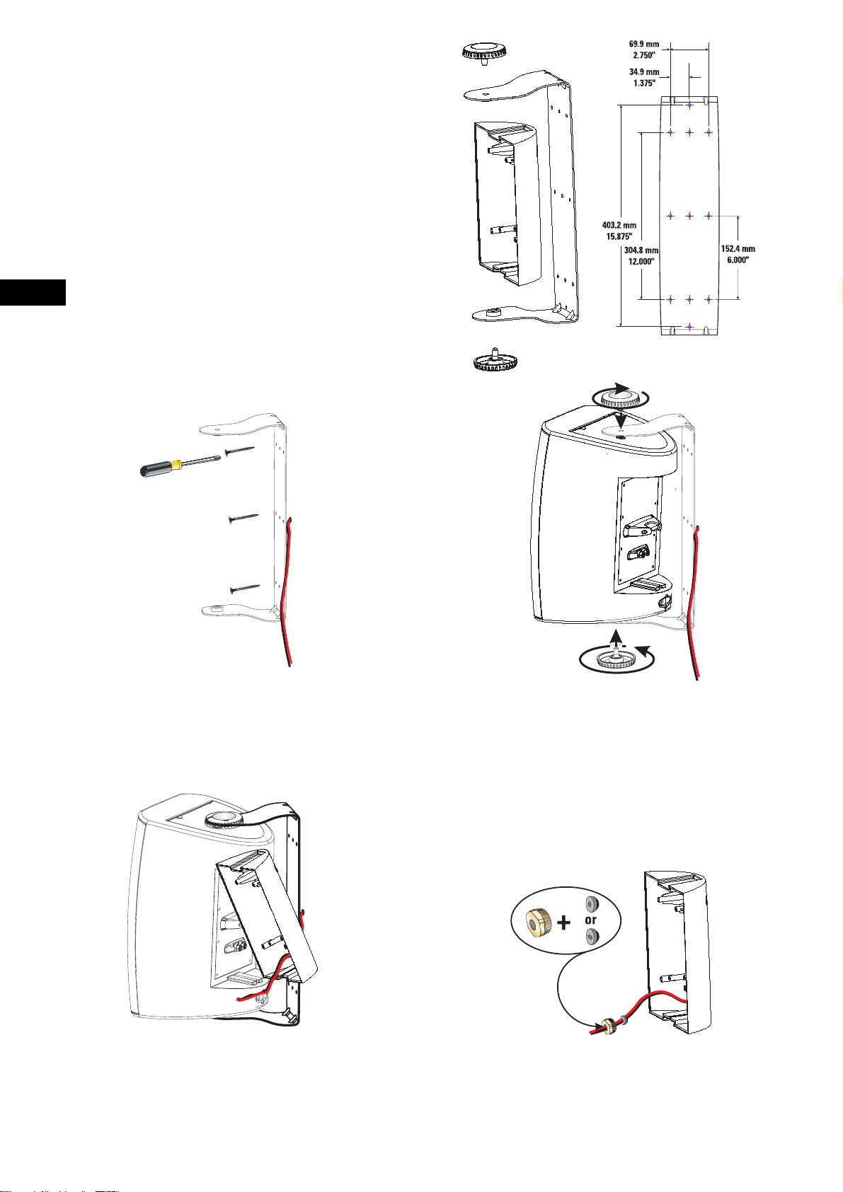
Optional YM-8 and YM-8T Yoke Mounts
The YM-8 and YM-8T yoke mounts provide for mounting on most
any surface and are adjustable on one axis. A cover plate is provided for the loudspeaker’s rear recess and is secured with a
retaining screw. The cover plate has a wiring feed-through hole,
complete with rubber grommet and compression nut to prevent
water from wicking down the cable and into the electrical connections.
The YM-8T yoke mount’s cover plate is equipped with an audio
matching transformer with 70V and 100V distributed audio input
capability.
Refer to the instructions included with the mount for detailed
information.
Optional YM-8 and YM-8T Mounting Procedure
1- Secure the yoke bracket to the mounting surface. Ensure
the mounting surface and supporting structure are appropriately strong enough to support the loudspeaker assembly
and any potential vibration or seismic activity.
3- Thread the speaker wiring through the cover plate.
2- Secure the loudspeaker to the yoke bracket.
4- Choose the appropriate rubber sealing gasket and thread
the speaker wire through it. Make sure the tapered side of
the gasket is toward the cover. Push the gasket into its seat,
and thread the nut over the speaker wire and tighten.
6
Optional YM-8 and YM-8T Mounting Procedure (continued)
EN
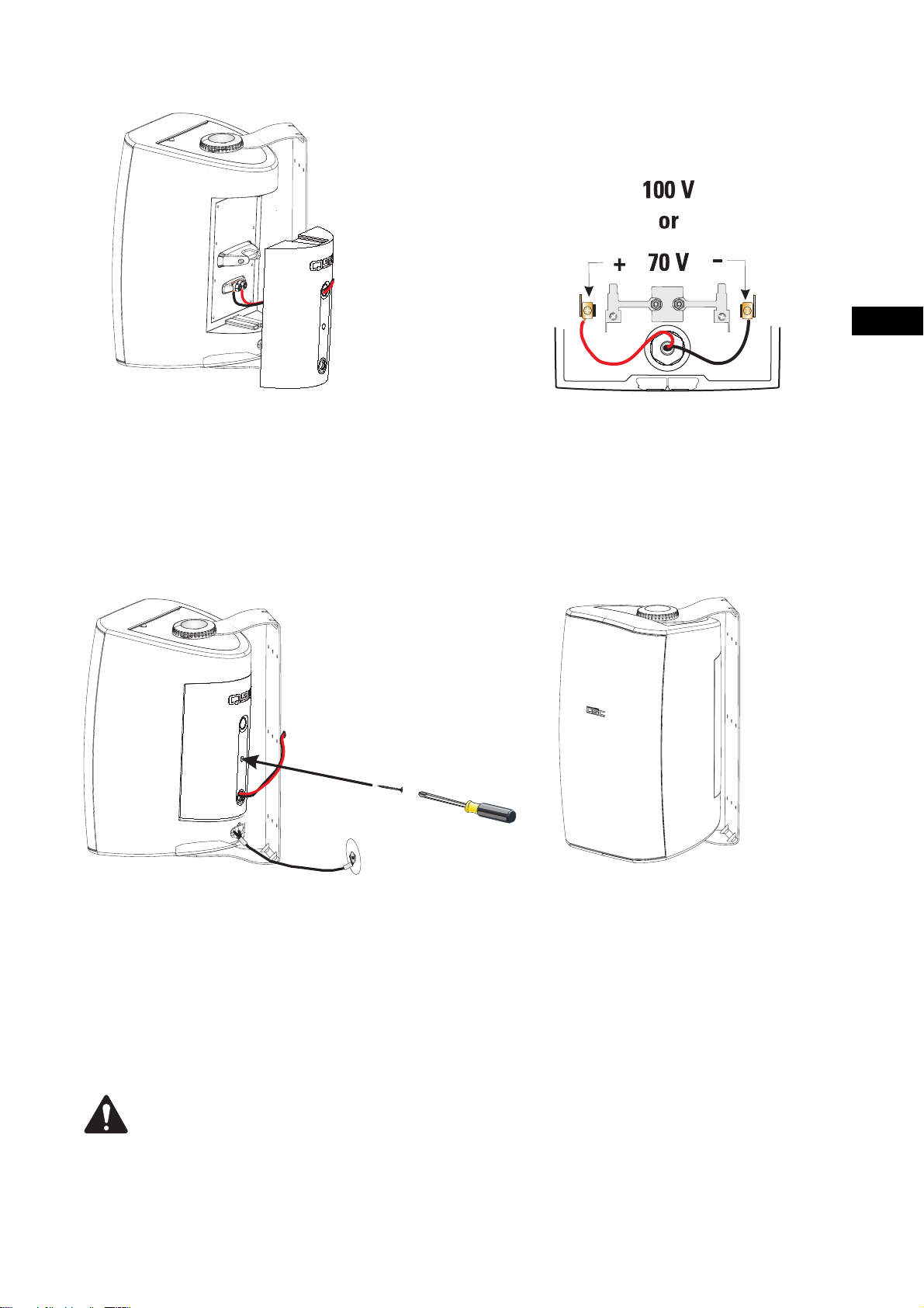
5- Strip the speaker wiring ends and connect the wires. If
using the YM-8, connect the wires directly to the binding
posts. If using the YM-8T, connect the 70V/100V terminals
in the cover assembly.
5a- The YM-8T cover assembly is equipped with the 70V/
100V matching transformer, a 4-position power selection
switch, and all required connections pre-wired. Just connect the speaker wires to the appropriate terminals inside
the cover, then install the cover onto the loudspeaker. Coverto-loudspeaker connections are made by the banana plugs
in the YM-8T assembly.
6- Align the cover on the back of the
loudspeaker and slide into place. The cover is designed to
fit only one way. Install the cover retaining screw to prevent
the cover from vibrating loose and to keep the connections
weather-tight. Attach a safety cable to the attachment point
on the bottom-back of the loudspeaker. Ensure the safety
cable, cable attachment technique, securing hardware, and
attachment points are strong enough to support the weight
of the loudspeaker in the event of a primary-mount failure.
IMPORTANT! PLEASE READ AND ENSURE THAT THE LOUDSPEAKER IS MOUNTED PROPERLY AND A SAFETY
CABLE IS INSTALLED TO RETAIN THE LOUDSPEAKER IN THE EVENT OF A MOUNTING FAILURE.
Ensure the mounting surface and supporting structure are appropriately strong enough to support the loudspeaker assembly and any potential vibration or seismic activity.
Attach a safety cable to the attachment point on the bottom-back of the loudspeaker. Ensure the safety cable,
cable attachment technique, securing hardware, and attachment points are strong enough to support several
times the weight of the loudspeaker in the event of a primary-mount failure.
7- Rotate the cabinet into the desired position and tighten
both of the mounting knobs.
7
EN
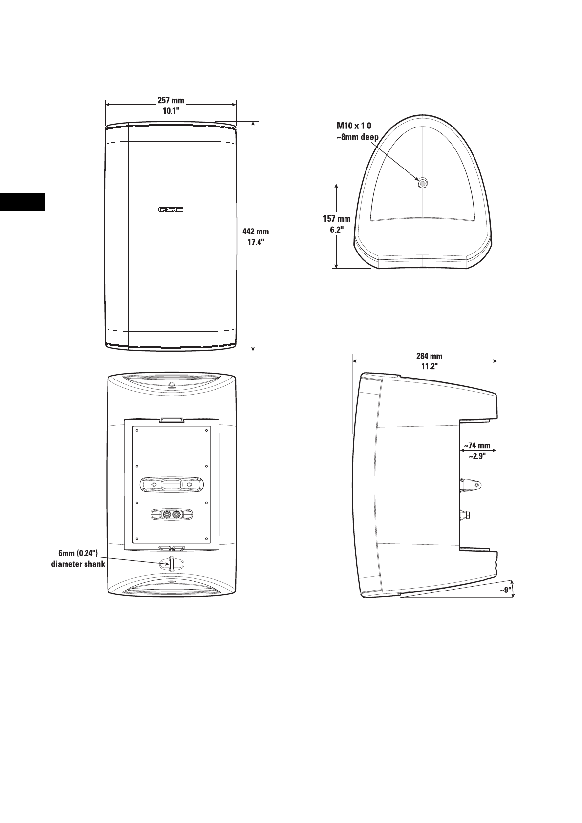
AD-S82 and AD-S82H Loudspeaker Dimensions
8

Specifications
AD-S82 AD-S82H
Frequency Response1: 85- 22k Hz (-6 dB) 80- 21k Hz (-6 dB)
55- 23k Hz (-10 dB) 60- 22k Hz (-10 dB)
Maximum Output
2
: 110 dB SPL continuous rms output 113 dB SPL continuous rms output
(calculated) 116 dB SPL peak output 119 dB SPL peak output
Impedance: 8 ohms nominal 8 ohms nominal
6.4 ohms minimum, 240 Hz 7.0 ohms minimum, 210 Hz
25 ohms maximum, 2.5k Hz 135 ohms maximum
Power Rating
3
:
rms (IEC 100 hrs): 100 watts rms 200 watts rms
recommended amp power: 200 watts rms 400 watts rms
Sensitivity: 90.0 dB, 1 watt, 1 meter, free field (4 pi) 90.5 dB, 1 watt, 1 meter, free field (4 pi)
Directivity Index:
500 Hz 3.8 4.0
1000 Hz 5.8 5.5
2000 Hz 12.6 11.7
4000 Hz 10.2 8.9
8000 Hz 9.8 8.6
16000 Hz 9.7 7.2
Q:
500 Hz 2.4 2.5
1000 Hz 3.8 3.6
2000 Hz 18.2 14.7
4000 Hz 10.4 7.7
8000 Hz 9.5 7.3
16000 Hz 9.2 5.3
EN
Weight: 16.2 lb. (19.6 lb.) 16.9 lb. (20.3 lb.)
(net (shipping))
All Models
Nominal Coverage: 90° horiz. x 60° vert.
Enclosure and Grill: high impact polystyrene, removable metal grill
Connectors: binding posts, 19 mm (0.75”) spacing, accepts wire and banana plugs
Optional 8 Ohm Mounting Hardware: QSC IntelliDock mount ID-8 or yoke mount YM-8
Optional 70V/100V Transformer
Equipped Mounting Hardware: QSC IntelliDock mount ID-8T or yoke mount YM-8T
ID-8T and YM-8T Power and Calculated Continuous Maximum Output (dB SPL) by Tap Selected:
70.7V line
100V line
Tap 1: 7.5W (99 dB) 15W (102 dB)
Tap 2: 15W (102 dB) 30W (105 dB)
Tap 3: 30W (105 dB) 60W (108 dB)
Tap 4: 60W (108 dB) n/a
NOTES:
1- All frequency ranges specified refer to measured free-field response (4 pi).
2- Calculated maximum peak SPL at 1 m, free-field, speaker operating at rated rms power pink noise input, 50 Hz to 20 kHz.
3- Maximum input power tested in accordance with IEC recommendations; 50 Hz to 20 kHz band limiting, 6 dB signal crest factor.
Specifications are subject to change without notice.
9
EN
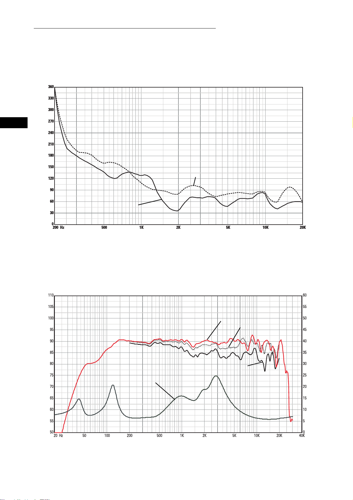
AD-S82 Response, Beamwidth, and Impedance Curves
AD-S82 Horizontal and Vertical Beamwidth Vs. Frequency
Horizontal
Beamwidth (degrees)
SPL (dB)
Vertical
Frequency (Hertz)
AD-S82 Response On-Axis, 20° Off-Axis, 40° Off-Axis, and Impedance Vs. Frequency
On Axis
20° Off Axis
40° Off Axis
10
Impedance
Impedance (ohms)
Frequency (Hertz)
Specifications are subject to change without notice.
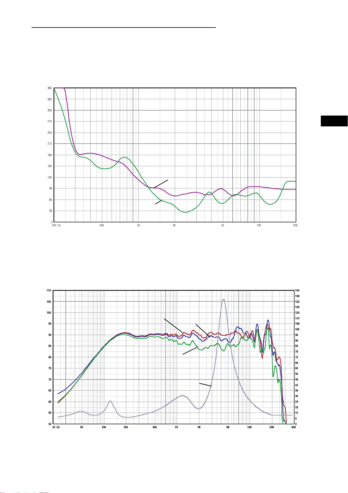
AD-S82H Response, Beamwidth, and Impedance Curves
AD-S82H Horizontal and Vertical Beamwidth Vs. Frequency
EN
Beamwidth (degrees)SPL (dB)
Horizontal
Vertical
Frequency (Hertz)
AD-S82H Response On-Axis, 20° Off-Axis, 40° Off-Axis, and Impedance Vs. Frequency
On Axis
20° Off Axis
40° Off Axis
Impedance
Frequency (Hertz)
Specifications are subject to change without notice.
Impedance (ohms)
11

Painting the AD-S82(H) Loudspeaker
The loudspeaker enclosure and grill can be painted to match any decor, provided the following precautions are observed. The
optional ID-8 IntelliDock and YM-8 yoke mount can also be painted. The cabinet is made of high impact polystyrene which requires
controlled painting procedures in order to obtain good results when painting. Use a paint “system” designed for polypropylene from
any reputable paint supplier.
1- Remove the grill.
2- If painting mount and loudspeaker as a unit: Attach the ID-8 or YM-8 so that the loudspeaker and mount can be painted as a
unit.
EN
3- If painting mount and loudspeaker separately: Mask the loudspeaker’s input connector and the ID-8’s interior.
4- Mask the woofer, tweeter, and port being certain not to apply tape directly to the drivers. Alternatively, the inside of the grill can
be completely masked and set in place on the loudspeaker enclosure for painting.
5- Wash the components to be painted with a mild soap and hot water. Be careful not to get water on or into either of the drivers or
the input connections. Rinse with hot water. Allow to dry thoroughly.
6- Scuff-sand the components to be painted using red Scotchbrite® pad or 320 - 400 grit sandpaper.
7- Using compressed air, remove all dust from the components to be painted. Do not blow compressed air directly into either driver.
8- Clean the components to be painted.
9- Using a clean, lint-free, white cloth, wipe the components to be painted with suitable prep solution.
10- Apply adhesion promoter.
11- Apply primer topcoat.
12- Apply paint.
13- Allow to dry for at least 8 hours before handling.
12
IMPORTANTES PRECAUCIONES DE SEGURIDAD
Y EXPLICACIÓN DE LOS SÍMBOLOS
1- Lea estas instrucciones.
2- Conserve estas instrucciones.
3- Observe todas las advertencias.
4- Siga todas las instrucciones.
5- Limpie solamente con un paño seco.
6- Instale de acuerdo con las instrucciones de QSC Audio Product y de un ingeniero profesional licenciado.
7- No instale cerca de ninguna fuente de calor tal como radiadores, registros de calor, estufas u otros aparatos (inclusive amplificadores) que produzcan calor.
8- Use solamente conectadores y accesorios de QSC Audio Products, Inc.
9- Use solo con montajes o soportes especificados por QSC Audio Products.
10- Refiera todo el servicio al personal calificado. Se requiere servicio cuando el aparato haya sido dañado de alguna manera.
El símbolo de un rayo con punta de flecha dentro de un triángulo equilátero tiene el propósito de alertar al
usuario de la presencia de voltaje “peligroso” no aislado dentro de la caja del producto, que puede ser de suficiente magnitud para constituir un riesgo de descarga eléctrica a los seres humanos.
Este signo de exclamación dentro de un triángulo equilátero tiene el propósito de alertar al usuario de la existencia de importantes instrucciones de operación y mantenimiento (servicio) en este manual.
¡ADVERTENCIA! Antes de colocar, instalar, equipar o suspender cualquier altavoz, inspeccione todo el herraje,
suspensión, gabinetes, transductores, soportes y equipo asociado para asegurarse de que estén en buenas
condiciones. Todo componente faltante, corroído, deformado o clasificado sin carga podría reducir significativamente la resistencia de la instalación, colocación o disposición. Cualquiera de tales condiciones reduce
gravemente la seguridad de la instalación y se debe corregir inmediatamente. Use sólo herraje que esté clasificado para las condiciones de carga de la instalación y para cualquier posible sobrecarga a corto plazo inesperada. Nunca exceda la capacidad nominal del herraje ni del equipo. Consulte a un ingeniero profesional
licenciado cuando tenga dudas o preguntas referentes a la instalación física del equipo.
ES
Garantía (sólo EE.UU.; consulte a su concesionario o distribuidor si desea información para otros países)
Liberación de responsabilidad
QSC Audio Products, Inc. no es responsable por ningún daño a los amplificadores, o a cualquier otro equipo, que sea causado por negligencia o por instalación y/o uso inadecuado de este altavoz.
Garantía limitada de 3 años de QSC Audio Products
QSC Audio Products, Inc. (“QSC”) garantiza que sus productos estarán libres de materiales y mano de obra defectuosos durante un
período de tres (3) años a partir de la fecha de la venta, y que reemplazará las piezas defectuosas y reparará los productos que no funcionen bien bajo esta garantía, cuando el defecto ocurra bajo condiciones normales de instalación y uso, siempre y cuando la unidad se
devuelva a nuestra fábrica o a una de nuestras estaciones autorizadas de servicio mediante transportación pre-pagada con una copia
del comprobante de compras (esto es, el recibo de la compra). Esta garantía dispone que el examen del producto devuelto debe indicar,
a nuestro criterio, un defecto de fabricación. Esta garantía no se extiende a ningún producto que haya estado sujeto a uso inadecuado,
negligencia, accidente, instalación incorrecta o cuando el código de la fecha se haya removido o alterado. QSC no será responsable por
daños incidentales o resultantes. Esta garantía le da derechos legales específicos. Esta garantía limitada se puede transferir libremente durante su período de vigencia.
El cliente puede tener otros derechos, que pueden variar entre estados.
En el evento que este producto se haya fabricado para su exportación y venta fuera de Estados Unidos o de sus territorios, esta
garantía limitada no será válida. La remoción del número de serie de este producto, o la compra de este producto a un concesionario no
autorizado, anulará esta garantía limitada.
Periódicamente se actualiza esta garantía. Para obtener la versión más reciente de la declaración de la garantía de QSC, por favor visite
www.qscaudio.com.
Comuníquese con nosotros al teléfono 800-854-4079 o visite nuestro sitio en la Web en www.qscaudio.com
.
13
ES
Introducción
Le agradecemos y felicitamos por su compra de los altavoces Acoustic Design AD-S82 de múltiples usos y para todo clima. Estos
productos representan lo más avanzado en sistemas de altavoces SR (refuerzo sonoro) ligeros, para todo clima. Para aprovechar al
máximo su inversión, le recomendamos que revise detenidamente este manual.
Los sistemas de altavoces AD-S82 tienen un diseño de amplitud completa, alta salida, de dos vías que produce un sonido de calidad superior y un alto nivel de presión sonora (SPL) en una caja ligera y para todo clima. Estos altavoces son una opción excelente
para una amplia variedad de aplicaciones SR.
Ángulos de cobertura
Antes de montar el altavoz, determine la orientación del montaje y los ángulos de cobertura deseados. Al salir de la fábrica los
altavoces tienen ángulos de cobertura de 90º (horizontal) x 60º (vertical) con el gabinete orientado verticalmente. El guíaondas se
puede rotar para intercambiar los ángulos de cobertura.
Rotación del guíaondas para alterar el patrón de cobertura de alta frecuencia
1- Retire la rejilla. Suavemente y de manera uniforme saque la rejilla de su ranura de retención para evitar doblarla.
2- Quite los ocho tornillos de retención del guíaondas. Se recomienda usar un destornillador
Phillips N.º 2.
3- Sujete el puerto del guíaondas y jale suavemente para sacar el guíaondas. Tenga cuidado
de no dañar las conexiones, el cableado o la junta que se encuentra entre el guíaondas y el
gabinete.
4- Gire la bocina 90° hacia la derecha o hacia la izquierda y vuélvala a colocar en su lugar.
Asegúrese de no ejercer tensión sobre el cableado ni desconectarlo al rotar el conjunto.
5- Antes de instalar los tornillos del guíaondas, levante un poco el conjunto y asegúrese de
que la junta esté adecuadamente instalada. Ajuste su posición si es necesario. Coloque el guíaondas en su lugar y coloque los tornillos. No los apriete excesivamente.
6- Vuelva a instalar la rejilla.
Conexión
Conecte las salidas + y - del amplificador directamente en los terminales + (rojo) y - (negro) del
altavoz. Si va a usar el herraje del montaje ID-8 o YM-8 opcional, consulte las instrucciones
que se incluyen con el herraje.
Mantenga la polaridad adecuada en las conexiones del altavoz y el amplificador en todo el sistema. Todos los
terminales con signo positivo del altavoz se deben conectar con los terminales de salida con signo positivo del
amplificador. Esto proporcionará la mejor salida de baja frecuencia posible de su sistema.
14
 Loading...