


HPR122i
1675 MacArthur Blvd., Costa Mesa, CA, 92626 USA
Main Number (714) 754-6175 or toll free (USA only) (800) 854-4079
Customer Service(714) 957-7150 or toll free (USA only) (800) 772-2834
HPR Series Powered Loudspeaker Products
User Manual
HPR122i 12-inch two-way
HPR152i 15-inch two-way
HPR153i 15-inch three-way
HPR151i 15-inch subwoofer
HPR181i 18-inch subwoofer
*TD-000234-00*
TD-000234-01 rev.B
Important Safety Precautions & Explanation of Symbols
Install in accordance with QSC Audio Product's instructions and under the supervision of a licensed Professional Engineer.
WARNING!
CAUTION: TO REDUCE THE RISK OF ELECTRIC SHOCK, DO NOT REMOVE THE COVER.
NO USER-SERVICEABLE PARTS INSIDE. REFER SERVICING TO QUALIFIED PERSONNEL.
The lightning flash with arrowhead symbol within an equ ilateral triangle is intended to alert the user to the presence of uninsulated “dangerous” voltage within the product's enclosure that may be of sufficient magnitude to
constitute a risk of electric shock to humans.
The exclamation point within an equilateral tria ngle is intended to alert the user to the presence of important
operating and maintenance (servicing) instructions in this manual.
1- Read these instructions.
2- Keep these instructions.
3- Heed all warnings.
4- Follow all instructions.
5- WARNING: To prevent fire or electric shock, do not expose this equipment to rain or moisture. Do not use this apparatus near water.
6- Clean only with a dry cloth.
7- Allow a minimum of 6” (152mm) clearance at cabinet back for convection cooling. Keep anything that might restrict airflow away from the rear of the enclosure
(i.e draperies, fabric, etc...). Do not block any ventilation openings. This product contains an internal power amplifier that produces heat.
8- Do not install near any heat sources such as radiators, heat registers, stoves, or other apparatus (including amplifiers) that produce heat.
9- Do not defeat the safety purpose of the grounding-type plug. The grounding plug has two blad es and a grounding prong. The third prong is provided for your
safety. If the provided plug does not fit your outlet, consult an electrician for the replacement of the obsolete outlet. Do not cut off the grounding prong or use an
adapter that breaks the grounding circuit. This apparatus must be properly grounded for your safety.
10- Protect the power cord from being walked on or pinched, particularly plugs, convenience receptacles, and the point where they exit from the apparatus.
11- This product is not equipped with an all-pole mains switch. To fully disconnect fr om the AC mains, the AC plug must be removed from the AC outlet or the
appliance coupler (IEC block) must be removed from the amplifier module. E nsure either the AC line cord plug or the appliance coupler are accessible in case
of emergency disconnect requirement.
12- Use only attachments/accessories specified by QSC Audio Products, Inc.
13- Use only with hardware, brackets, stands, and components sold with the apparatus or by QSC Audio Products, Inc.
14- Unplug the apparatus during lightning storms or when unused for long periods of time.
15- Refer all servicing to qualified service personnel. Servicing is required when the apparatus has been damaged in any way, such as power supply cord or
plug is damaged, liquid has been spilled or objects have fallen into the apparatus, the apparatus has been exposed to rain or moisture, does not operate normally,
or has been dropped.
16- Before placing, installing, rigging, or suspending any speaker product, inspect all hardware, suspension, cabinets, transducers, brackets and associated
equipment for damage. Any missing, corroded, deformed, or non-load rated component could significantly reduce the strength of the installation or placement.
Any such condition severely reduces the safety of the installation and should be immediately corrected. Use only hardware which is rated for the loading conditions of the installation and any possible short-term, unexpected overloading. Never exceed the rating of the hardware or equipment.
17- Consult a licensed, Professional Engineer regarding physical equipment installation. All local, state and national regulations regarding the safety and operation of equipment are understood and adhered to.
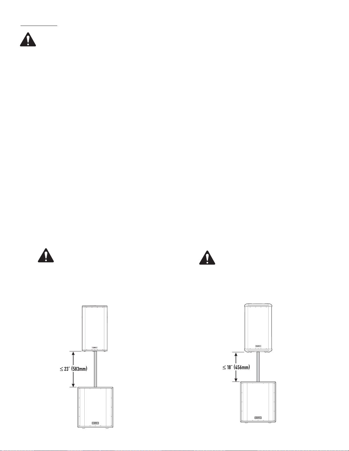
18- HPR152i WARNING! Do not use a loudspeaker support pole longer than 26” (660mm) when supported by QSC’s HPR151i or HPR181i subwoofer.
19- HPR122i WARNING! Do not use a loudspeaker support pole longer than 31” (787mm) when supported by QSC’s HPR151i or HPR181i subwoofer.
20- Do not use the HPR152i, HPR153i, HPR151i, or HPR181i oriented horizontally. Horizontal orientation can cause overheating and thermal limiting. The cooling
fins on the amplifier module must be vertically oriented in order to efficiently dissipate the heat generated by the amplifier.
21- The appliance shall not be exposed to dripping or splashing and no objects filled with liquids, such as vases, shall be placed on the apparatus.
2
Introduction
Congratulations and thank you for your purchase of this professional, powered loudspeaker product. To get the most from your investment, we
recommend you review all the information provided in this User Manual.
The HPR self-powered loudspeakers provide excellent sound quality, durable construction and clean, efficient, on-board amplification. Amplifiers are matched to the drivers with active equalization and precise crossover control. Active power limiting and thermal management extends
the life of drivers and the amplifier. The HPR series solves many application challenges with its great sound, built-in protect ion systems and selfcontained portability. HPR is the perfect solution for public performances, corporate events and private parties demanding flexible and excellent
sounding system solutions.
All models are self-powered using efficient amplifiers. AC line connection is fast and easy; an IEC-style quick-disconnect ensures reliable AC
mains connection while providing an easy-to-remove power cord for cabinet mobility. Audio enters the self-powered loudspeaker via a female
XLR connector with an additional parallel-wired male XLR output for daisy-chaining. No outboard signal processing is required as all models feature on-board filtering. The two-way and three-way full-range loudspeakers feature a switchable 100 Hz low-cut filter for use when subwoofers
are part of the system. Subwoofer models have two full-range input connectors (left and right) and two sets of output connectors; one pair featuring a 100 Hz low-cut filter and one pair passing full-range signal.
Rear-panel LEDs alert the user to AC power status, input signal presence, and limiter operation. Additionally, a blue front-panel "power on" LED
provides valuable visual power confirmation. It can also be disabled for applications where light toward the audience
may interfere with stage aesthetics. All models feature a 21-step detent Gain control allowing precise control and repeatable setup. The enclosures are made of high-quality plywood and are texture-coated in black. The models HPR122i, HPR152i and HPR153i have integral M10 suspension points for permanent installation and "flying" applications. Features vary by model, so please refer to sales brochures or the specifications
section of this manual for specific model information.
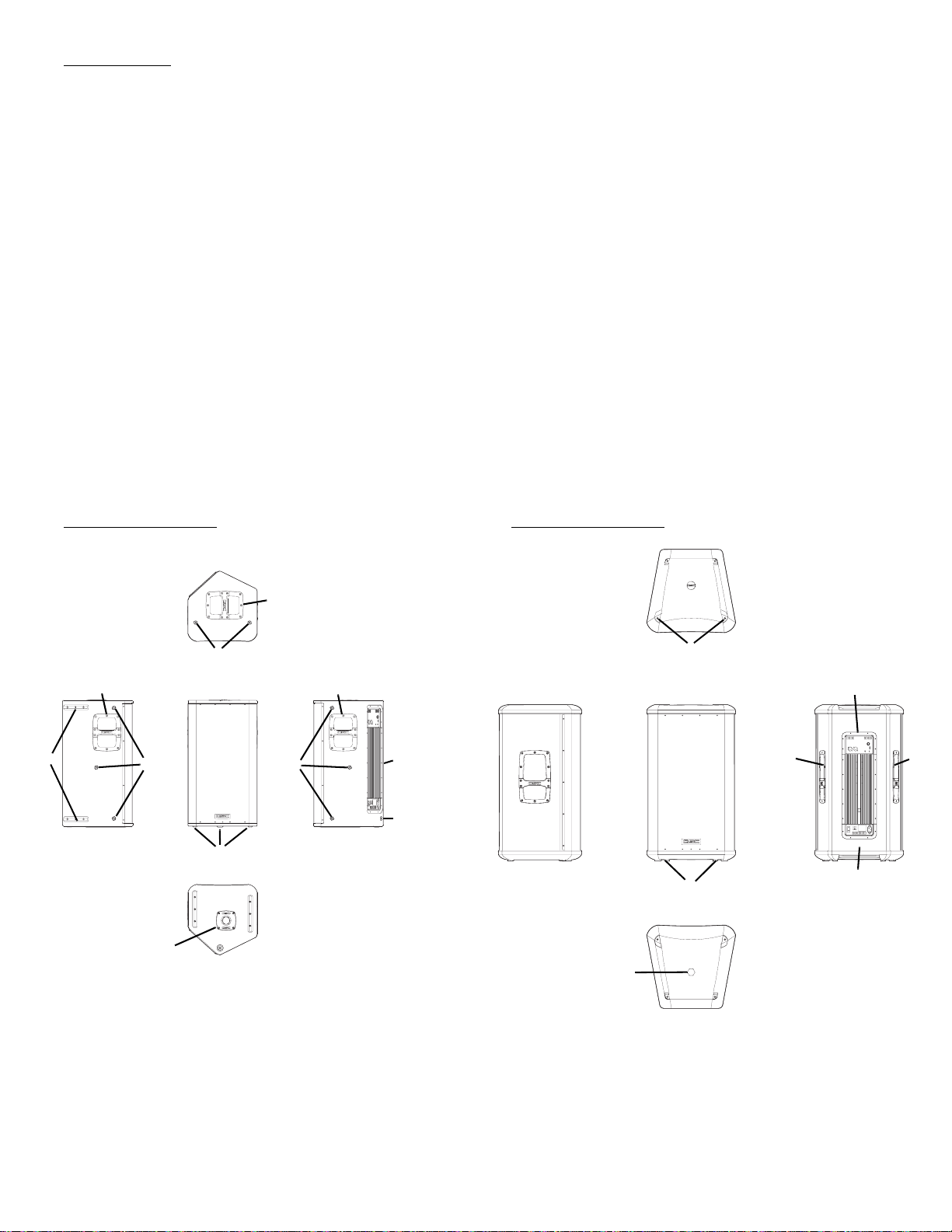
HPR122i Features HPR152i Features
2
6
22
5
66
1
3
5
4
6
6
4
2
3
5
1
6
2
1- Pole Cup 4- Power Amplifier
2- Handles 5- Slip-resistant Feet
3- Grill 6- Rigging points
3
HPR153i Features
5
2
3
4
1
2
5
1- Power Amplifier 4- Slip-resistant Feet
2- Handles 5- Rigging Points
3- Grill
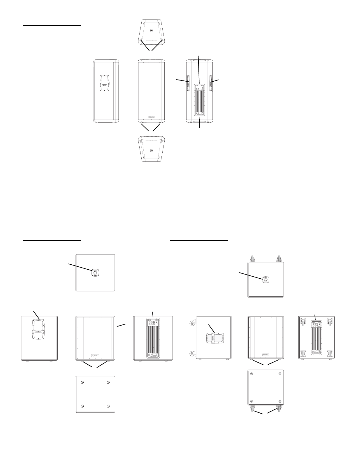
HPR151i Features HPR181i Features
1
2
2
3
5
4
2
1
4
3
5
6
1- Pole Cup 4- Power Amplifier
2- Handles 5- Slip-resistant Feet
4
3- Grill 6- Casters (HPR181W only)
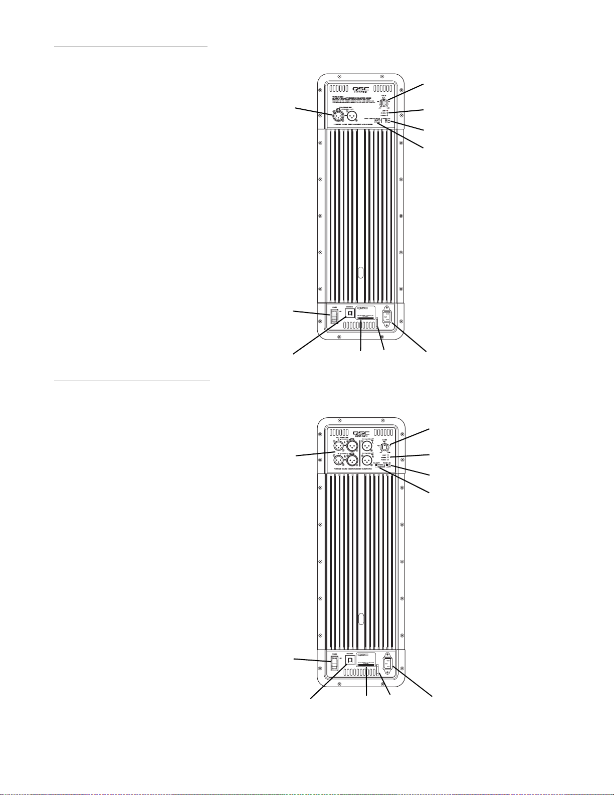
Full Range Amplifier Detail
2
1- Input and Output Connector(s)
2- Gain Control
3- Power, Signal, and Clip LED Indicators
4- Front LED Switch
5- 100 Hz Low-Cut Filter Switch
6- Power Switch
7- Circuit Breaker
8- Serial Number Plate
9- Power Cord Tether Lance
10- IEC Power Inlet
Subwoofer Amplifier Detail
1
6
7
9
8
3
4
5
10
1- Input and Output Connector(s)
2- Gain Control
3- Power, Signal, and Clip LED Indicators
4- Front LED Switch
5- Polarity Switch
6- Power Switch
7- Circuit Breaker
8- Serial Number Plate
9- Power Cord Tether Lance
10- IEC Power Inlet
2
1
6
9
7
8
3
4
5
10
5
Installation
Before placing, installing, rigging, or suspending any speaker product, inspect all hardware, suspension, cabinets, transd ucers, brackets
and associated equipment for damage. Any missing, corroded, deformed, or non-load rated component could significantly reduce the
strength of the installation or placement. Any such condition severely reduces the safety of the installation and should be immediately
corrected. Use only hardware which is rated for the loading conditions of the installation and any possible short-term, unexpected overloading. Never exceed the rating of the hardware or equipment.
Consult a licensed, Professional Engineer regarding physical equipment installation. Ensure that all local, state and national regulations
regarding the safety and operation of loudspeakers and related equipment are understood and adhered to.
How They Should Be Used
HPR122i: The HPR122i was designed to sit on the floor, stage, subwoofer enclosure, be suspended, or be pole mounted on a 35mm diameter
loudspeaker support pole. The pole can be part of a stand-alone loudspeaker stand or be inserted into the pole cup of the HPR151i or
HPR181i. Pole length must be no longer than 31” (787mm) when supported by the HPR151i or HPR181i subwoofer.
HPR152i: The HPR152i was designed to sit on the floor, stage, subwoofer enclosure, be suspended, or be pole mounted on a 35mm diameter
loudspeaker support pole. The pole can be part of a stand-alone loudspeaker stand or be inserted into the pole cup of the HPR151i or
HPR181i. Pole length must be no longer than 26” (660mm) when supported by the HPR151i or HPR181i subwoofer.
HPR153i: The HPR153i was designed to be suspended, or sit on the floor, stage, or on top of the subwoofer enclosure. Do not attempt to pole
mount this loudspeaker! There is no pole cup provided.
HPR151i: The HPR151i was designed to sit on the floor or on the stage. A pole cup on the top of the enclosure accepts 35mm loudspeaker
mounting poles. Rubber feet on the enclosure’s bottom help to minimize enclosure movement during operation. Do not pole mount or stack
more than one enclosure on top of the HPR151i enclosure.
HPR181i: The HPR181i was designed to sit on the floor or on the stage. A pole cup on the top of the enclosure accepts 35mm loudspeaker
mounting poles. Rubber feet on the enclosure’s bottom help to minimize enclosure movement during operation. Do not pole mount or stack
more than one enclosure on top of the HPR181i enclosure. As the casters will wear during normal use, it may be required to insert small foam
pieces between the wheels and frames to minimize rattling at high output levels.
HPR122i WARNING!
Do not use a loudspeaker support
pole longer than 31” (787mm)
when supported by the HPR151i or
HPR181i subwoofer. Note- each
pole cup is approximately 4”
(102mm) deep.
HPR152i WARNING!
Do not use a loudspeaker support
pole longer than 26” (660mm)
when supported by the HPR151i or
HPR181i subwoofer. Note- each
pole cup is approximately 4”
(102mm) deep.
6
Installation (continued)
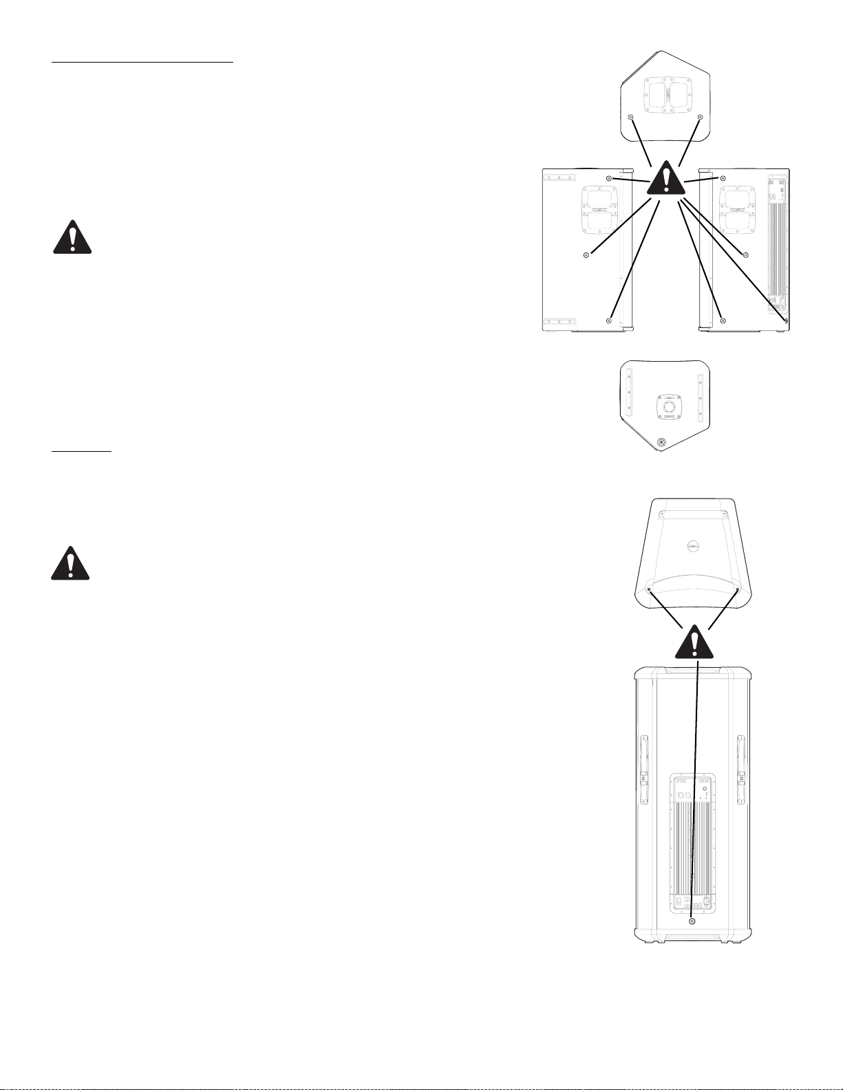
Pick Points (suspended installations)
The HPR152i and HPR153i enclosures feature three load-rated pick points.
The HPR122i enclosure features nine load-rated pick points. As shipped
from the factory, each pick point has a bolt or plug installed to retain the
air-tight design of the enclosure. Never operate the loudspeaker with the
pick points open (unsealed) as it will degrade the performance of the
product.
Ensure all pick-point fasteners are installed and correctly
tightened in order to maintain enclosure’s rated strength.
Additionally, air leaks resulting from missing hardware will
degrade the loudspeaker’s performance.
Use only QSC’s M10 forged shoulder eye bolts. Contact QSC
Technical Services department for complete information.
Cooling
This is a self-powered loudspeaker containing an internal power amplifier
that produces heat. Allow a minimum of 6” (152mm) clearance at cabinet
back for convection cooling. Keep anything that might restrict airflow
away from the rear of the enclosure (i.e draperies, fabric, etc...).
Pickpoints on the
HPR122i
Pickpoints on the
HPR152i and
HPR153i
Do not use the HPR152i, HPR153i, HPR151i, or HPR181i oriented
horizontally. Horizontal orientation can cause overheating and
thermal limiting. The cooling fins on the amplifier module must be
vertically oriented in order to efficiently dissipate the heat generated by the amplifier.
Do not install enclosures with their rear panels exposed to direct
sunlight. Direct sunlight will heat the amplifier module and reduce
its ability to produce full output. Install sunshades if the application merits.
Maximum ambient temperature for full performance to specification is 40° C. (104° F.).
Do not install enclosures where exposed to rain or other water
sources. The enclosure is not weatherproof. Outdoor installations
must provide protection from the elements.
7
AC Mains
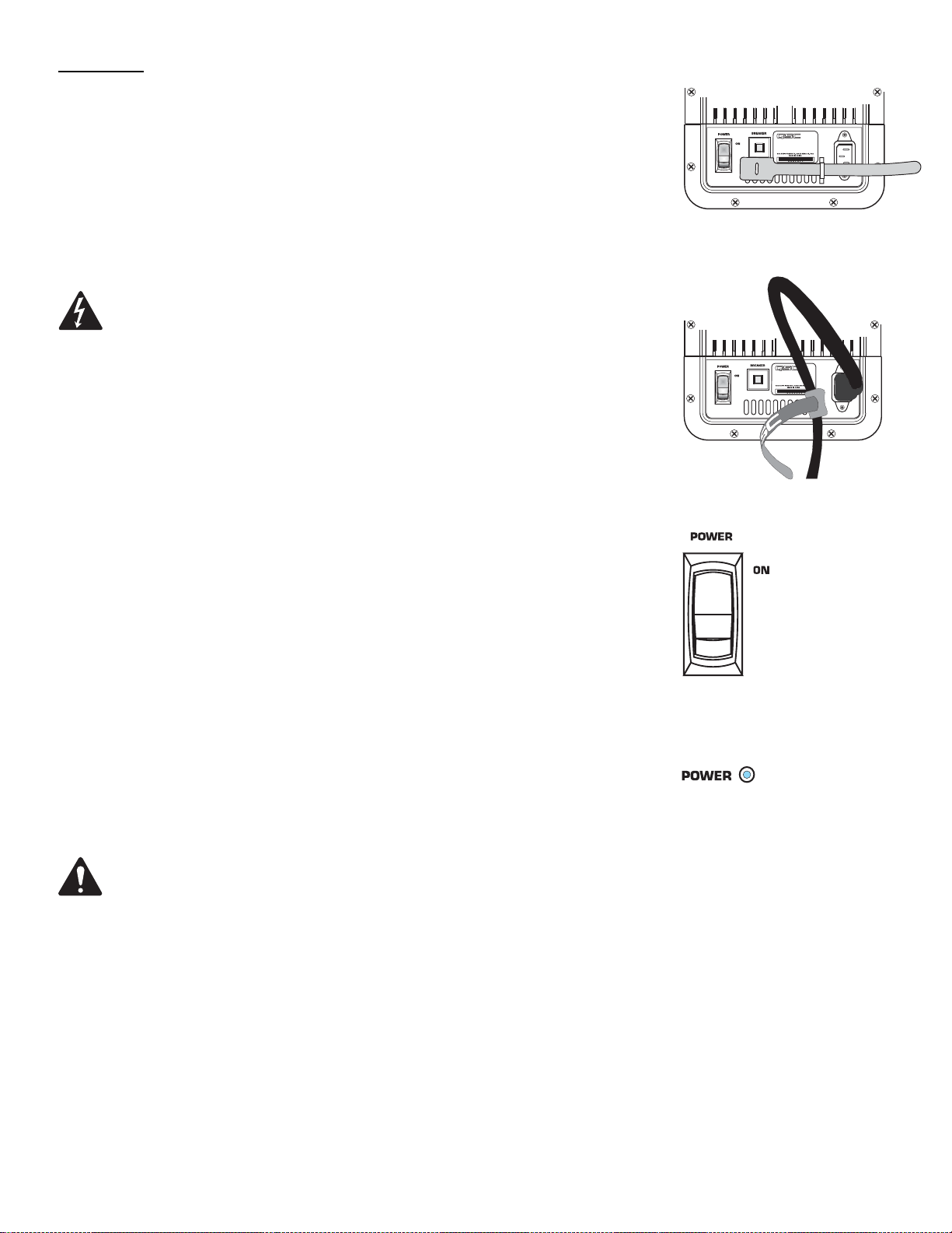
Connect AC power to the IEC socket on the back of the amplifier by locating
the IEC connector-end of the AC power cord and inserting it fully into the IEC
inlet on the power amplifier module. NOTE: Turn off the AC power switch
before connecting AC power.
An AC power cord hook-and-loop tether (retention strap) is provided to minimize the risk of the power cord being inadvertently pulled from its connection
at the back of the amplifier. To use the tether, pass it through the chassis
lance (adjacent the IEC socket) and then capture the AC power cord by looping it in the tether before closing the hook-and-loop strap.
The correct AC line voltage is shown on the serial number label, on
the rear panel. Connecting to the wrong line voltage may damage the
amplifier or increase the risk of electric shock.
AC Mains Disconnection
Turn the AC power switch to the off position. To remove the AC mains cord,
grasp the IEC connector’s plastic body and pull, removing the connector from
the socket.
Power Switch
Push in on the top of the rocker switch to apply AC mains power to the powered loudspeaker. Push in on the bottom of the rocker switch to turn the powered loudspeaker off.
When turned on, the blue POWER indicator LED and the red LIMIT (limiter)
indicator LED will illuminate; after a few seconds the red LIMIT indicator will
extinguish.
AC power cord
tether use-
1- Insert tether
through chassis
lance adjacent IEC
inlet.
2- Form a small
loop in the AC
power cord. Capture the AC power
cord in the tether
and secure by pulling the smaller end
through the hole in
the tether’s large
end.
AC power switch
LED POWER Indicator
The blue LED POWER indicator will illuminate when the AC Power switch is
in the “ON” position, the AC mains power cord is connected properly , and the
AC mains are functioning properly. The LED POWER indicator will extinguish
when the AC Power switch is in the “off” position or AC mains power has
been removed from the loudspeaker.
If the POWER indicator does not illuminate when the Power switch is placed
in the “on” position, verify the AC mains line cord is properly attached to the
loudspeaker and plugged into the AC outlet. Verify the outlet is functioning
properly.
If the AC mains cordset is serviceable and the AC mains outlet is operating properly, but the loudspeaker fails to operate, the loudspeaker
may require servicing. Contact QSC’s Technical Services department.
System Power Sequencing
Proper power turn on sequence can help to prevent unexpected sounds from
your system (pops, clicks, thumps). These unintended sounds can damage
drivers and cause audience members to question the professionalism of the
sound team. Turn on and off the system in the proper order to avoid unexpected sounds.
Power On Sequence: Turn on all source devices (CD players, mixers), turn
on subwoofer, then turn on the “top-boxes” (HPR122i, HPR152i and HPR153i).
Power “on” indicator LED
Power Off Sequence: Turn off the top-boxes, turn off the subwoofer, then
turn off the source devices.
8
 Loading...