


WD Series
Corrosion Resistant Heater
Installation, Operation & Maintenance Instructions
Specifications
Model |
|
|
|
Output |
Heater |
Motor |
Motor |
Motor |
Temp |
|
Ship Weight |
||
Number |
KW |
Volts |
Phase |
BTU/HR |
Amps |
Volts |
Phase |
Amps |
Rise |
CFM |
lbs (kg) |
||
WD02112A |
2 |
120 |
1 |
6,824 |
16.7 |
120 |
1 |
1.554 |
9 |
700 |
60 |
(27.2) |
|
WD02812A |
2 |
208 |
1 |
6,824 |
9.6 |
208 |
1 |
0.896 |
9 |
700 |
60 |
(27.2) |
|
WD02212A |
2 |
240 |
1 |
6,824 |
8.3 |
240 |
1 |
0.777 |
9 |
700 |
60 |
(27.2) |
|
WD03112A |
3 |
120 |
1 |
10,236 |
25.0 |
120 |
1 |
1.554 |
14 |
700 |
60 |
(27.2) |
|
WD03812A |
3 |
208 |
1 |
10,236 |
14.4 |
208 |
1 |
0.896 |
14 |
700 |
60 |
(27.2) |
|
WD03212A |
3 |
240 |
1 |
10,236 |
12.5 |
240 |
1 |
0.777 |
14 |
700 |
60 |
(27.2) |
|
WD03712A |
3 |
277 |
1 |
10,236 |
10.8 |
277 |
1 |
0.673 |
14 |
700 |
60 |
(27.2) |
|
WD03832A |
3 |
208 |
3 |
10,236 |
8.3 |
208 |
1 |
0.896 |
14 |
700 |
60 |
(27.2) |
|
WD03232A |
3 |
240 |
3 |
10,236 |
7.2 |
240 |
1 |
0.777 |
14 |
700 |
60 |
(27.2) |
|
WD03432A |
3 |
480 |
3 |
10,236 |
3.6 |
480 |
1 |
0.388 |
14 |
700 |
60 |
(27.2) |
|
WD05812A |
5 |
208 |
1 |
17,060 |
24.0 |
208 |
1 |
0.896 |
23 |
700 |
60 |
(27.2) |
|
WD05212A |
5 |
240 |
1 |
17,060 |
20.8 |
240 |
1 |
0.777 |
23 |
700 |
60 |
(27.2) |
|
WD05712A |
5 |
277 |
1 |
17,060 |
18.1 |
277 |
1 |
0.673 |
23 |
700 |
60 |
(27.2) |
|
WD05412A |
5 |
480 |
1 |
17,060 |
10.4 |
480 |
1 |
0.388 |
23 |
700 |
60 |
(27.2) |
|
WD05832A |
5 |
208 |
3 |
17,060 |
13.9 |
208 |
1 |
0.896 |
23 |
700 |
60 |
(27.2) |
|
WD05232A |
5 |
240 |
3 |
17,060 |
12.0 |
240 |
1 |
0.777 |
23 |
700 |
60 |
(27.2) |
|
WD05432A |
5 |
480 |
3 |
17,060 |
6.0 |
480 |
1 |
0.388 |
23 |
700 |
60 |
(27.2) |
|
WD05632A |
5 |
600 |
3 |
17,060 |
4.8 |
240 |
1 |
1.8 |
23 |
1450 |
75 |
(34) |
|
WD07812A |
7.5 |
208 |
1 |
25,590 |
36.1 |
208 |
1 |
0.896 |
34 |
700 |
60 |
(27.2) |
|
WD07212A |
7.5 |
240 |
1 |
25,590 |
31.3 |
240 |
1 |
0.777 |
34 |
700 |
60 |
(27.2) |
|
WD07712A |
7.5 |
277 |
1 |
25,590 |
27.1 |
277 |
1 |
0.673 |
34 |
700 |
60 |
(27.2) |
|
WD07412A |
7.5 |
480 |
1 |
25,590 |
15.6 |
480 |
1 |
0.388 |
34 |
700 |
60 |
(27.2) |
|
WD07832A |
7.5 |
208 |
3 |
25,590 |
20.8 |
208 |
1 |
0.896 |
34 |
700 |
60 |
(27.2) |
|
WD07232A |
7.5 |
240 |
3 |
25,590 |
18.0 |
240 |
1 |
0.777 |
34 |
700 |
60 |
(27.2) |
|
WD07432A |
7.5 |
480 |
3 |
25,590 |
9.0 |
480 |
1 |
0.388 |
34 |
700 |
60 |
(27.2) |
|
WD07632A |
7.5 |
600 |
3 |
25,590 |
7.2 |
240 |
1 |
1.8 |
34 |
1450 |
75 |
(34) |
|
WD10212A |
10 |
240 |
1 |
34,120 |
41.7 |
240 |
1 |
0.777 |
22 |
1450 |
60 |
(27.2) |
|
WD10712A |
10 |
277 |
1 |
34,120 |
36.1 |
277 |
1 |
0.673 |
22 |
1450 |
60 |
(27.2) |
|
WD10412A |
10 |
480 |
1 |
34,120 |
20.8 |
480 |
1 |
0.388 |
22 |
1450 |
60 |
(27.2) |
|
WD10832A |
10 |
208 |
3 |
34,120 |
27.8 |
208 |
1 |
0.896 |
22 |
1450 |
60 |
(27.2) |
|
WD10232A |
10 |
240 |
3 |
34,120 |
24.1 |
240 |
1 |
0.777 |
22 |
1450 |
60 |
(27.2) |
|
WD10432A |
10 |
480 |
3 |
34,120 |
12.0 |
480 |
1 |
0.388 |
22 |
1450 |
60 |
(27.2) |
|
WD10632A |
10 |
600 |
3 |
34,120 |
9.6 |
240 |
1 |
1.8 |
33 |
2400 |
75 |
(34) |
|
WD12812A |
12.5 |
208 |
1 |
42,650 |
60.1 |
208 |
1 |
1.793 |
27 |
1450 |
60 |
(27.2) |
|
WD12212A |
12.5 |
240 |
1 |
42,650 |
52.1 |
240 |
1 |
1.554 |
27 |
1450 |
60 |
(27.2) |
|
WD12832A |
12.5 |
208 |
3 |
42,650 |
34.7 |
208 |
1 |
1.793 |
27 |
1450 |
60 |
(27.2) |
|
WD12232A |
12.5 |
240 |
3 |
42,650 |
30.1 |
240 |
1 |
1.554 |
27 |
1450 |
60 |
(27.2) |
|
WD12432A |
12.5 |
480 |
3 |
42,650 |
15.0 |
480 |
1 |
0.777 |
27 |
1450 |
60 |
(27.2) |
|
WD12632A |
12.5 |
600 |
3 |
42,650 |
12.0 |
240 |
1 |
1.8 |
27 |
2400 |
75 |
(34) |
|
WD15812A |
15 |
208 |
1 |
51,180 |
72.1 |
208 |
1 |
1.793 |
20 |
2400 |
110 (49.9) |
||
WD15212A |
15 |
240 |
1 |
51,180 |
62.5 |
240 |
1 |
1.554 |
20 |
2400 |
110 (49.9) |
||
WD15412A |
15 |
480 |
1 |
51,180 |
31.3 |
480 |
1 |
0.777 |
20 |
2400 |
110 (49.9) |
||
WD15832A |
15 |
208 |
3 |
51,180 |
41.6 |
208 |
1 |
1.793 |
20 |
2400 |
110 (49.9) |
||
WD15232A |
15 |
240 |
3 |
51,180 |
36.1 |
240 |
1 |
1.554 |
20 |
2400 |
110 (49.9) |
||
WD15432A |
15 |
480 |
3 |
51,180 |
18.0 |
480 |
1 |
0.777 |
20 |
2400 |
110 (49.9) |
||
WD15632A |
15 |
600 |
3 |
51,180 |
14.5 |
240 |
1 |
1.8 |
20 |
2400 |
125 |
(56.6) |
|
WD20412A |
20 |
480 |
1 |
68,240 |
41.7 |
480 |
1 |
0.777 |
26 |
2400 |
120 |
(54.4) |
|
WD20232A |
20 |
240 |
3 |
68,240 |
48.1 |
240 |
1 |
1.554 |
26 |
2400 |
120 |
(54.4) |
|
WD20432A |
20 |
480 |
3 |
68,240 |
24.1 |
480 |
1 |
0.777 |
26 |
2400 |
120 |
(54.4) |
|
WD20632A |
20 |
600 |
3 |
68,240 |
19.3 |
240 |
1 |
1.8 |
26 |
2400 |
135 |
(61.2) |
|
WD25832A |
25 |
208 |
3 |
85,300 |
69.4 |
208 |
1 |
1.793 |
33 |
2400 |
120 |
(54.4) |
|
WD25232A |
25 |
240 |
3 |
85,300 |
60.1 |
240 |
1 |
1.554 |
33 |
2400 |
120 |
(54.4) |
|
WD25432A |
25 |
480 |
3 |
85,300 |
30.1 |
480 |
1 |
0.777 |
33 |
2400 |
120 |
(54.4) |
|
WD25632A |
25 |
600 |
3 |
85,300 |
24.1 |
240 |
1 |
1.8 |
33 |
2400 |
135 |
(61.2) |
|
WD30832A |
30 |
208 |
3 |
102,360 |
83.3 |
208 |
1 |
1.793 |
39 |
2400 |
120 |
(54.4) |
|
WD30232A |
30 |
240 |
3 |
102,360 |
72.2 |
240 |
1 |
1.554 |
39 |
2400 |
120 |
(54.4) |
|
WD30432A |
30 |
480 |
3 |
102,360 |
36.1 |
480 |
1 |
0.777 |
39 |
2400 |
120 |
(54.4) |
|
WD30632A |
30 |
600 |
3 |
102,360 |
28.9 |
240 |
1 |
1.8 |
39 |
2400 |
135 |
(61.2) |
|
WD39432A |
39 |
480 |
3 |
133,068 |
46.9 |
480 |
1 |
0.777 |
51 |
2400 |
120 |
(54.4) |
|
WD39632A |
39 |
600 |
3 |
133,068 |
37.6 |
240 |
1 |
1.8 |
51 |
2400 |
135 |
(61.2) |
|
|
|
|
|
|
|
|
|
|
|
|
|
|
|
NOTE: Heaters over 48 amps require supplemental fusing.
SAVE THESE INSTRUCTIONS
PPD 41616 |
12/13 |
5200-11199-002 |
IMPORTANT INSTRUCTIONS
|
WARNING |
! |
|||
|
|
|
|
|
|
WHEN usiNg ELECTriC APPLiANCEs, BAsiC PrECAu- |
6. |
Do not operate any heater after it malfunctions. Disconnect |
|||
TioNs sHouLD ALWAys BE foLLoWED To rEDuCE THE |
|
power at service panel and have heater inspected by a rep- |
|||
risK of firE, ELECTriC sHoCK, AND iNJury To PEr- |
|
utable electrician before using. |
|||
soNs, iNCLuDiNg THE foLLoWiNg: |
7. |
Do not use outdoors. |
|||
1. |
read all instructions before installing or using this heater. |
8. |
To disconnect heater, turn controls to off, and turn off |
||
2. |
This heater is a commercial/industrial product not intended |
|
power to heater circuit at main disconnect panel. |
||
|
|
|
|||
|
for use in a residential setting. |
9. |
Do not insert or allow foreign objects to enter any ventilation |
||
3. |
This heater has hot and arcing or sparking parts inside and |
|
or exhaust opening as this may cause an electric shock, fire, |
||
|
or damage to the heater. |
||||
|
is not intended for use in hazardous atmospheres where |
|
|||
|
|
|
|
||
|
flammable vapors, gases, liquids or other combustible |
10. |
To prevent a possible fire, do not block air intake or exhaust |
||
|
atmospheres as defined in the National Electrical Code are |
|
in any manner. |
||
|
used or stored. failure to comply can result in explosion or |
11. |
use this heater only as described in this manual. Any other |
||
|
fire. |
||||
|
|
use not recommended by the manufacturer may cause fire, |
|||
4. |
This heater is hot when in use. To avoid burns, do not let |
|
|||
|
electric shock, or injury to persons. |
||||
|
bare skin touch hot surfaces. Keep combustible materials, |
12. |
When installing, see iNsTALLATioN iNsTruCTioNs for |
||
|
such as furniture, pillows, bedding, papers, clothes, etc. and |
||||
|
|
additional warnings and precautions. |
|||
|
curtains at least 3 feet (0.9 m) from the front of the heater. |
|
|||
|
13. for safe and efficient operation, and to extend the life of your |
||||
5. |
Extreme caution is necessary when any heater is used by or |
||||
|
heater, |
keep your heater clean - see MAiNTENANCE |
|||
|
near children or invalids and whenever the heater is left |
|
|||
|
|
iNsTruCTioNs. |
|||
|
operating and unattended. |
|
|||
|
NOT FOR RESIDENTIAL USE. |
||||
|
|
||||
|
|
|
|
|
|
INSTALLATION
INSTRUCTIONS
|
WARNING |
! |
|
|
|
|
|||
|
|
|
|||||||
To prevent a possible fire, injury to persons or damage to the |
4. |
To reduce the risk of fire, do not store or use gasoline or other |
|||||||
heater, adhere to the following: |
|
|
flammable vapors and liquids in the vicinity of the heater. |
||||||
Important Note: This heater must be installed by a qualified |
5. |
The ceiling or wall mounting structure and the anchoring pro- |
|||||||
person. |
|
|
visions must be of sufficient strength to support the combined |
||||||
|
|
weight |
of |
the |
heater |
and mounting |
bracket. see |
||
1. Disconnect all power coming to heater at main service panel |
|
||||||||
|
specificatinos for total weight. |
|
|||||||
before wiring or servicing. |
|
|
|
||||||
|
6. |
Heater |
must |
be |
mounted |
for horizontal air |
flow only. The |
||
2. All wiring procedures and |
connections must be in accor- |
||||||||
|
heater must be mounted at least 7’ (2134 mm) above the |
||||||||
dance with the National and |
Local Codes having jurisdiction |
|
|||||||
|
floor to avoid accidental contact with the fan blade which |
||||||||
and the heater must be grounded. |
|
||||||||
|
could cause injury. |
|
|
||||||
|
|
|
|
|
|||||
CAUTION: All electrical conduit and fittings must be listed for |
7. |
Keep at least 5’ (1524 mm) clearance in front of the heater. |
|||||||
watertight applications to maintain the NEMA 4X enclosure |
|
refer to figure 2 for side, top and back clearance require- |
|||||||
classification to prevent hose-directed water from entering elec- |
|
ments. |
|
|
|
|
|
||
trical box. |
|
8. |
Do not mount mercury type thermostat directly on unit. |
||||||
|
|
||||||||
3. Verify the power supply voltage coming to heater matches |
|
Vibration could cause heater to malfunction. |
|
||||||
the ratings as shown on the heater nameplate. |
9. |
outlet grille is factory formed with louvers set at a 45 ° angle. |
|||||||
|
|
||||||||
CAUTION: ENErgiziNg HEATEr AT A VoLTAgE grEATEr |
|
This is the minimum angle allowable to avoid potential over- |
|||||||
THAN THE VoLTAgE PriNTED oN THE NAMEPLATE WiLL |
|
heating. Louvers may be opened up to 90° if desired to allow |
|||||||
DAMAgE THE HEATEr AND VoiD THE WArrANTy AND |
|
for better air throw by bending each louver outward. see |
|||||||
CouLD CAusE A firE. |
figure 3. |
|
General
Heater Location Instructions:
Arrange units so their discharge air streams:
A.Are subjected to minimum interference from columns, machinery and partitions.
B.Wipe exposed walls without blowing directly at them.
C.Are directed away from room occupants in comfort heating.
D.Are directed along the windward side when installed in a building exposed to a prevailing wind.
if not provided with internal thermostat, locate remote thermostat on interior partition walls or posts away from cold drafts, internal heat sources and away from heater discharge air streams.
E
Figure 1
2

|
|
Ceiling |
|
|
Ceiling |
Ceiling |
|
|
A |
|
|
9" Min. |
|
|
|
|
|
|
|
(229 mm) |
|
D |
|
|
|
|
|
|
|
||
|
|
8" Min. |
|
|
|
Wall |
|
|
|
(203 mm) |
B |
|
|
||
|
|
|
|
|
Wall |
||
|
|
|
|
|
|
||
|
|
|
Wall |
|
|
|
|
|
|
|
|
|
6" |
6" Min. |
|
|
|
|
|
|
(152 mm) |
||
|
|
|
|
|
(152 mm) |
||
|
|
|
|
|
|
||
|
|
|
|
C |
|
|
|
|
|
|
|
7' Min. |
|
7' Min. |
|
|
|
|
|
(2134 mm) |
|
(2134 mm) |
|
Figure 2 |
|
Floor |
|
Floor |
Floor |
||
|
|
Dimensions Inches (mm) |
Wiring |
|
|||
kW |
A |
B |
C |
D |
Refer to wiring diagram included with the unit. |
||
2-10 |
13 (330) |
19.5 (495) |
18 (457) |
19.5 (495) |
The wiring diagram can be found on the inside of the door to the |
||
12.5-39.0 |
20 (508) |
31 (787) |
27 (686) |
24.2 (615) |
wiring compartment. should you have any questions, please |
||
contact Technical service at 800-642-4328. Have your model |
|||||||
|
|
|
|
|
|||
small rooms can be heated by one unit heater. Where two walls |
number found on the name plate for reference. |
|||
are exposed, the heater should be mounted as shown in |
|
|
|
|
figure 1. |
|
|
|
|
Large rooms require multi-unit installations. Number and capaci- |
|
|
|
|
ALL ELECTriCAL CoNDuiT AND fiTTiNgs MusT BE LisTED |
||||
ty of units will be determined by volume of building and square |
for WATErTigHT APPLiCATioNs To MAiNTAiN THE NEMA |
|||
feet of floor area to be heated. Arrange units to provide perimeter |
4X ENCLosurE CLAssifiCATioN To PrEVENT HosE |
|||
air circulation where each unit supports the air stream from |
DirECTED WATEr froM ENTEriNg ELECTriCAL BoX. |
|||
another. |
|
|
|
|
NOTE: All electrical wiring must be done according to National |
||||
|
||||
Mounting Heaters with supplied Universal Mounting Bracket
NOTICE — These heaters are designed for wall and ceiling mounting with horizontal air discharge only. other modes of mounting voids factory warranty.
1.Height above floor
A.in areas where ceiling height is more than 12 feet (3658 mm), recommended mounting height is approximately 10 feet (3048 mm) to underside of heater.
B.for ceiling heights of 12 feet (3658 mm) or less, maximum mounting height is determined by use of the mounting bracket offered for these heaters. Minimum spacing to ceiling is 9” (229 mm). (see figure 2.)
C.in either case the minimum mounting height is 7 feet (2134 mm) from floor to bottom of heater. (figure 2)
Electrical and local codes by a qualified person.
IMPORTANT NOTE - Installation Screw Lug Torque: During transportation it is possible screw lug connections can loosen. After installation, before power is turned on to the heater, check all screw lug connections for tightness to a recommended minimum torque of 35 in-lbs. (3.9 N-m). A tool is included for tightening lugs in hard to reach locations
ELECTriC sHoCK HAzArD. ANy iNsTALLATioN iNVoLViNg ELECTriC HEATErs MusT BE PErforMED By A quALifiED PErsoN AND MusT BE EffECTiVELy grouNDED iN ACCorDANCE WiTH THE NATioNAL ELECTriCAL CoDE To ELiMiNATE sHoCK HAzArD.
2.spacing to adjacent walls (see figure 2).
A.rear of case to back wall 6” (152mm) minimum.
B.side of case to side wall 8” (203 mm) minimum.
NOTE: if two or more units are operated in the same enclosed air space, their discharges should be directed to aid in development of mass air movement for uniform heat dispersal.
45° Minimum
Angle
Figure 3 - Louver Adjustment
1.Connect heater according to the voltage and frequency specified on the nameplate.
2.All units are provided with control and power terminal blocks for customer’s connection.
3.Protection against overheating is provided by an internal automatic thermal cutout (manual reset cutout optional) which opens the electric circuit if the normal air-flow is restricted or stopped. Cutout automatically energizes heater on removal of the obstruction. if optional manual reset is tripped, determine cause before re-energizing.
THE sysTEM DEsigNEr is rEsPoNsiBLE for THE sAfETy of THis EquiPMENT AND sHouLD iNsTALL ADEquATE BACK-uP CoNTroLs AND sAfETy DEViCEs WiTH THEir ELECTriC HEATiNg EquiPMENT. WHErE THE CoNsEquENCEs of fAiLurE CouLD rEsuLT iN PErsoNAL iNJury or ProPErTy DAMAgE, BACK-uP CoNTroLs ArE EssENTiAL.
3
4.Heaters are equipped with fan delay control. This control continues fan operation for a short time after elements are deenergized to dissipate residual heat.
fAN BLADE roTATioN MusT BE CHECKED. if AirfLoW is NoT MoViNg ouT THrougH THE ouTLET griLLE, iNTErCHANgE ANy TWo of THE THrEE iNCoMiNg suPPLy PoWEr LEADs oN THrEE-PHAsE uNiTs oNLy.
Optional Equipment
•Built-in Thermostat (bulb and capillary type) for automatic temperature control. The thermostat controls the heating elements and fan simultaneously to achieve set temperature.
The Lo setting of the thermostat is approximately 40˚f and the Hi setting is approximately 90˚f.
•Mode Switch (heater on, heater off, fan only) to permit air flow with or without energizing the heating elements. The switch is accessible from outside the NEMA 4X enclosure.
•Pilot Light to indicate when heating elements are energized.
•Internal Fusing
•Manual Reset Limit
•ON/OFF Switch
•for wiring diagram containing options, see label on inside cover of terminal box.
OPERATING
INSTRUCTIONS
1.Heater must be properly installed before operation.
2.To check out the installation, turn the Mode switch to the off position. Turn power oN to the heater at the main disconnect panel and check to see that the heater is not operating. if it is operating, disconnect power and check wiring.
3.rotate built-in (or remote mounted) thermostat clockwise to the highest heat setting. With Heat-Cool switch in off position, heater should not operate.
4.Turn Heat-Cool selector switch to the fan only position. The fan should come on and operate with no heat.
5.Turn Heat-Cool selector switch to the Heat position. The fan and heater should come on producing heat.
6.The heater should be allowed to operate with the thermostat at max or high heat until room temperature reaches the desired level. The thermostat should then be rotated counterclockwise until the heater elements turn off (an audible click). This should set the thermostat to cycle the heater on and off to maintain the ambient temperature. fine adjustments may need to be made to obtain the desired room ambient. slight rotating of the thermostat in the clockwise direction will increase the room ambient while rotation in the counterclockwise direction will lower the room ambient. if remote thermostat is provided, follow the instructions provided with thermostat
NOTE: A built in fan delay will cause the fan to run after the elements turn off to dissipate residual heat.
NOTE: if a Disconnect switch option is provided, this switch will be accessible from the outside of the control box and will be marked oN and off accordingly. in the off position, the heater will not operate.
NOTE: if a Manual-reset Cutout option is provided, the rEsET button will be marked and accessible on the control panel. This safety control will operate only if the heater overheats.
Do NoT TAMPEr WiTH or ByPAss ANy sAfETy LiMiTs iNsiDE HEATEr.
MAINTENANCE
INSTRUCTIONS
it is important to keep this heater clean. your heater will give you years of service and comfort with only minimum care. To assure efficient operation follow the simple instructions below.
ALL sErViCiNg BEyoND siMPLE CLEANiNg THAT rEquirEs DisAssEMBLy sHouLD BE PErforMED By quALifiED sErViCE PErsoNNEL.
To rEDuCE risK of firE AND ELECTriC sHoCK or iNJury, DisCoNNECT ALL PoWEr CoMiNg To HEATEr AT MAiN sErViCE PANEL AND CHECK THAT THE ELEMENT is CooL BEforE sErViCiNg or PErforMiNg MAiNTENANCE.
User Cleaning Instructions:
1.Turn off power to heater and allow elements to cool.
2.Vacuum or hose off heater with water (at city pressure) before activating for next heating season to remove accumulated dust or lint which otherwise may smoke or incinerate on initial heat up.
3.return power to heater and check to make sure it is operating properly.
Maintenance Cleaning Instructions:
(To be performed only by Qualified Service Personnel)
At least annually, the heater should be cleaned and serviced by a qualified service person to assure safe and efficient operation. This should include as necessary, vacuuming dust and debris from the elements and fan, and check all screw lug connections for tightness to a recommended minimum torque of 35 in-lbs. (3.9 N-m) using the included tool(s) for hard to reach lugs if necessary. After completing the cleaning and servicing, the heater should be fully reassembled and checked for proper operation.
IMPORTANT NOTE: for heaters used in a hose down application, it is recommended that periodically after the heater has been hosed down (with power off at panel) the wiring enclosure cover be opened and the interior inspected for water penetration. if water is discovered, the heater must be repaired by a qualified electrician to assure the seals are properly installed.
During each cleaning, all seals should be inspected for damage as it is critical that they maintain a water tight seal. if damage is discovered (such as tears or cracking), they should be replaced or repaired with an appropriate silicone sealant.
4
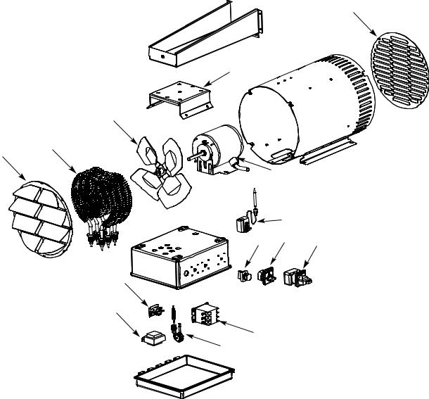
Replacement Parts
5
4
2
1
6
10
|
13 |
|
12 |
11 |
14 |
|
8
9, 9A
7, 7A
3
Elements (1)
Heater KW |
120 V |
208 V |
240 V |
277 V |
480 V |
600 V |
2 |
1802-11012-001 |
1802-11012-002 |
1802-11012-003 |
- |
- |
|
3 |
1802-11012-001 |
1802-11012-002 |
1802-11012-003 |
1802-11012-004 |
1802-11012-004 |
|
5 |
- |
1802-11012-005 |
1802-11012-006 |
1802-11012-007 |
1802-11012-008 1PH |
1802-11012-027 |
|
|
|
|
|
1802-11012-007 3 PH |
|
7.5 |
- |
1802-11012-011 |
1802-11012-012 |
1802-11012-009 |
1802-11012-008 |
1802-11012-027 |
10 |
- |
1802-11012-010 |
1802-11012-011 |
1802-11012-012 |
1802-11012-013 |
1802-11012-028 |
12.5 |
- |
1802-11013-001 |
1802-11013-002 |
- |
1802-11013-003 |
1802-11013-021 |
15 |
- |
1802-11013-004 |
1802-11013-005 |
- |
1802-11013-006 |
1802-11012-027 |
20 |
- |
- |
1802-11013-007 |
- |
1802-11013-008 |
1802-11012-010 |
25 |
- |
1802-11013-001 |
1802-11013-002 |
- |
1802-11013-003 |
1802-11012-011 |
30 |
- |
1802-11013-004 |
1802-11013-005 |
- |
1802-11013-006 |
1802-11013-022 |
39 |
- |
- |
- |
- |
1802-11013-009 |
1802-11013-023 |
|
|
|
|
|
|
|
|
|
|
|
|
|
|
Mechanical Parts and Cutout - KW Dependent
Heater KW |
fan Blade (2) |
Limit (3) |
Mounting Bracket(4) |
inlet grill (5) |
outlet grill (6) |
2kw, 3kw, 5kw, 7.5kw |
1210-11007-003 |
4520-11013-000 |
1215-11081-000 |
2504-11018-000 |
2504-11019-001 |
10kw |
1210-11007-002 |
|
|
|
|
12.5kw |
1210-11008-000 |
4520-11013-001 |
1215-11081-001 |
2504-11020-000 |
2504-11021-001 |
15kw, 20kw, 25kw, 30kw, 39kw |
1210-11008-001 |
|
|
|
|
|
|
|
|
|
|
5
Electrical Parts
|
Heater Line |
Heater Control |
Heater |
|
|
fan Delay |
|
|
|
|
Terminal Block |
Heater KW |
Voltage |
Voltage |
Phase |
Contactor (7) |
Contactor (7A) |
relay(8) |
Transformer (9) |
|
Transformer (9A) |
|
(Not shown) |
2kw, 3kw, |
120 |
24 |
1 |
5018-0006-000 |
N/A |
5018-11005-000 |
5814-0003-006 |
|
N/A |
5823-0004-002 |
|
|
|
|
|
|
|
|
|
|
|
|
|
5kw, 7.5kw, |
208 |
24 |
1 or 3 |
|
|
|
5814-0003-000 |
|
|
|
(480V also req |
|
|
|
|
|
|
|
|
|
|
|
|
10kw |
240 |
24 |
|
|
|
|
5814-0003-000 |
|
|
2900-0030-000) |
|
|
|
|
|
|
|
|
|
|
|
|
|
|
277 |
24 |
1 |
|
|
|
5814-0003-001 |
|
|
|
|
|
|
|
|
|
|
|
|
|
|
|
|
|
480 |
24 |
1 or 3 |
|
|
|
5814-0003-002 |
|
|
|
|
|
|
|
|
|
|
|
|
|
|
|
|
|
600 |
24 |
3 |
5018-0006-000 |
5018-0005-004 |
5018-11005-000 |
5814-0003-000 |
490015027 |
|
|
|
|
|
|
|
|
|
|
|
|
|
|
|
2kw, 3kw, |
120 |
120 |
1 |
5018-0006-001 |
N/A |
5018-11005-001 |
N/A |
|
N/A |
|
|
|
|
|
|
|
|
|
|
|
|
|
|
5kw, 7.5kw, |
208 |
120 |
1 or 3 |
|
|
|
5814-0003-003 |
|
|
|
|
|
|
|
|
|
|
|
|
|
|
|
|
10kw |
240 |
120 |
|
|
|
|
5814-0003-003 |
|
|
|
|
|
|
|
|
|
|
|
|
|
|
|
|
|
277 |
120 |
1 |
|
|
|
5814-0003-004 |
|
|
|
|
|
|
|
|
|
|
|
|
|
|
|
|
|
480 |
120 |
1 or 3 |
|
|
|
5814-0003-005 |
|
|
|
|
|
|
|
|
|
|
|
|
|
|
|
|
|
600 |
120 |
3 |
5018-0006-001 |
5018-0005-005 |
5018-11005-001 |
5814-0003-003 |
490015027 |
|
|
|
|
|
|
|
|
|
|
|
|
|
|
|
unfused |
208 |
24 |
3 |
5018-0006-000 |
5018-11005-000 |
|
5814-0003-000 |
|
|
|
|
|
|
|
|
|
|
|
|
|
|
|
|
large units |
240 |
24 |
|
|
|
|
5814-0003-000 |
|
|
|
|
|
|
|
|
|
|
|
|
|
|
|
|
12.5kw,15kw, |
480 |
24 |
|
|
|
|
5814-0003-002 |
|
|
|
|
|
|
|
|
|
|
|
|
|
|
|
|
|
600 |
24 |
|
|
5018-0005-004 |
5018-11005-000 |
5814-0003-000 |
490015027 |
|
|
|
|
|
|
|
|
|
|
|
|
|
|
|
|
208 |
120 |
3 |
5018-0006-001 |
5018-11005-001 |
|
5814-0003-003 |
|
|
|
|
|
|
|
|
|
|
|
|
|
|
|
|
|
240 |
120 |
|
|
|
|
5814-0003-003 |
|
|
|
|
|
|
|
|
|
|
|
|
|
|
|
|
|
480 |
120 |
|
|
|
|
5814-0003-005 |
|
|
|
|
|
|
|
|
|
|
|
|
|
|
|
|
|
600 |
120 |
|
|
5018-0005-005 |
5018-11005-001 |
5814-0003-003 |
490015027 |
|
|
|
|
|
|
|
|
|
|
|
|
|
|
|
fused |
208 |
24 |
1 |
5018-0006-000 |
5018-11005-000 |
|
5814-0003-000 |
|
|
480034002 |
|
|
|
|
|
|
|
|
|
|
|
|
|
large units |
240 |
24 |
|
|
|
|
5814-0003-000 |
|
|
|
|
|
|
|
|
|
|
|
|
|
|
|
|
|
480 |
24 |
|
|
|
|
5814-0003-002 |
|
|
|
|
|
|
|
|
|
|
|
|
|
|
|
|
|
208 |
120 |
1 |
5018-0006-001 |
5018-11005-001 |
|
5814-0003-003 |
|
|
|
|
|
|
|
|
|
|
|
|
|
|
|
|
|
240 |
120 |
|
|
|
|
5814-0003-003 |
|
|
|
|
|
|
|
|
|
|
|
|
|
|
|
|
|
480 |
120 |
|
|
|
|
5814-0003-005 |
|
|
|
|
|
|
|
|
|
|
|
|
|
|
|
|
Electrical Parts (Continued)
|
|
|
Heater Line |
Heater Control |
Heater |
|
Mode switch (11) |
Pilot Light green (12) |
|
Heater KW |
|
Voltage |
Voltage |
Phase |
Motor (10) |
(Accy) |
(Accy) |
||
2kw, 3kw, |
120 |
24 |
1 |
3900-11029-002 |
5216-11016-000 |
|
3510-11009-000 |
||
5kw, 7.5kw, |
|
208 |
24 |
1 or 3 |
3900-11029-000 |
|
|
|
|
10kw |
|
240 |
24 |
|
|
|
|
|
|
|
|
|
277 |
24 |
1 |
3900-11029-001 |
|
|
|
|
|
480 |
24 |
1 or 3 |
3900-11029-000 |
|
|
|
|
|
|
|
|
|
|
|
|
|
|
|
|
600 |
24 |
3 |
|
|
|
|
|
|
|
|
|
|
|
|
|
||
2kw, 3kw, |
120 |
120 |
1 |
3900-11029-002 |
|
|
3510-11009-001 |
||
|
|
|
|
|
|
|
|
|
|
5kw, 7.5kw, |
208 |
120 |
1 or 3 |
3900-11029-000 |
|
|
|
||
|
|
|
|||||||
10kw |
|
|
|
|
|
|
|
||
|
240 |
120 |
|
|
|
|
|
||
|
|
|
|
|
|
|
|
|
|
|
|
277 |
120 |
1 |
3900-11029-001 |
|
|
|
|
|
|
|
|
|
|
|
|
|
|
|
|
480 |
120 |
1 or 3 |
3900-11029-000 |
|
|
|
|
|
|
600 |
120 |
3 |
|
|
|
|
|
|
|
|
|
|
|
|
|
|
|
unfused |
|
208 |
24 |
3 |
3900-11031-000 |
|
|
3510-11009-000 |
|
large units |
|
240 |
24 |
|
|
|
|
|
|
12.5kw,15kw |
|
480 |
24 |
|
|
|
|
|
|
|
|
|
600 |
24 |
3 |
|
|
|
|
|
|
|
|
|
|
||||
|
|
|
208 |
120 |
3 |
3900-11031-000 |
|
|
3510-11009-001 |
|
|
240 |
120 |
|
|
|
|
|
|
|
|
|
480 |
120 |
|
|
|
|
|
|
|
|
600 |
120 |
3 |
|
|
|
|
fused |
208 |
24 |
1 |
3900-11031-000 |
5216-11016-000 |
|
3510-11009-000 |
||
|
|
|
|
|
|
|
|
|
|
large units |
240 |
24 |
|
|
|
|
|
||
|
|
|
|
|
|||||
|
|
|
|
|
|
|
|
|
|
|
|
480 |
24 |
|
|
|
|
|
|
|
|
|
|
|
|
|
|
|
|
|
|
208 |
120 |
1 |
3900-11031-000 |
|
|
3510-11009-001 |
|
|
|
|
|
|
|
|
|
|
|
|
|
240 |
120 |
|
|
|
|
|
|
|
|
|
|
|
|
|
|
|
|
|
|
480 |
120 |
|
|
|
|
|
|
|
|
|
|
|
|
|
|
|
|
6
Disconnect Switch (14)
size |
Part |
Amps |
Number |
40 |
4529-11009-031 |
60 |
4529-11009-032 |
100 |
4529-11009-033 |
125 |
4529-11009-034 |
|
|
Miscellaneous
Description |
Part Number |
Thermostat (13) |
5813-11010-000 |
gasket (Not shown) |
5206-11009-000 |
|
|
7

LIMITED WARRANTY
All products manufactured by Marley Engineered Products are warranted against defects in workmanship and materials for one year from date of installation. This warranty does not apply to damage from accident, misuse, or alteration; nor where the connected voltage is more than 5% above the nameplate voltage; nor to equipment improperly installed or wired or maintained in violation of the product’s installation instructions. All claims for warranty work must be accompanied by proof of the date of installation.
The customer shall be responsible for all costs incurred in the removal or reinstallation of products, including labor costs, and shipping costs incurred to return products to Marley Engineered Products service Center. Within the limitations of this warranty, inoperative units should be returned to the nearest Marley authorized service center or the Marley Engineered Products service Center, and we will repair or replace, at our option, at no charge to you with return freight paid by Marley. it is agreed that such repair or replacement is the exclusive remedy available from Marley Engineered Products.
THE ABoVE WArrANTiEs ArE iN LiEu of ALL oTHEr WArrANTiEs EXPrEssED or iMPLiED, AND ALL iMPLiED WArrANTiEs of MErCHANTABiLiTy AND fiTNEss for A PArTiCuLAr PurPosE WHiCH EXCEED THE AforEsAiD EXPrEssED WArrANTiEs ArE HErEBy DisCLAiMED AND EXCLuDED froM THis AgrEEMENT. MArLEy ENgiNEErED ProDuCTs sHALL NoT BE LiABLE for CoNsEquENTiAL DAMAgEs ArisiNg WiTH rEsPECT To THE ProDuCT, WHETHEr BAsED uPoN NEgLigENCE, TorT, sTriCT LiABiLiTy, or CoNTrACT.
some states do not allow the exclusion or limitation of incidental or consequential damages, so the above exclusion or limitation may not apply to you. This warranty gives you specific legal rights, and you may also have other rights which vary from state to state.
for the address of your nearest authorized service center, contact Marley Engineered Products in Bennettsville, sC, at 1-800-642-4328. Merchandise returned to the factory must be accompanied by a return authorization and service identification tag, both available from Marley Engineered Products. When requesting return authorization, include all catalog numbers shown on the products.
HOW TO OBTAIN WARRANTY SERVICE AND WARRANTY PARTS PLUS GENERAL INFORMATION
1. Warranty service or Parts |
1-800-642-4328 |
2. Purchase replacement Parts |
1-800-654-3545 |
3. general Product information |
www.marleymep.com |
Note: When obtaining service always have the following:
1.Model number of the product
2.Date of manufacture
3.Part number or description
470 Beauty Spot Rd. East
Bennettsville, SC 29512 USA
PPD 41616 |
12/13 |
5200-11199-002 |
 Loading...